![[NASA Logo]](../Images/nasaball.gif)
| |
NASA Procedures and Guidelines |
This Document is Obsolete and Is No Longer Used.
|
|
P.1 Purpose
P.2 Applicability
P.3 Authority
P.4 Applicable Documents and Forms
P.5 Measurement/Verification
P.6 Cancellation
1.1 Background
1.2 Framework for Systems Engineering Procedural Requirements
1.3 Framework for Systems Engineering Capability
1.4 Document Organization
2.1 Roles and Responsibilities
2.2 Tailoring and Customization
3.1 Introduction
3.2 Requirements for the Common Technical Processes
4.1 Introduction
4.2 Activities Prior to Contract Award
4.3 During Contract Performance
4.4 Contract Completion
5.1 Life Cycle
5.2 Life-cycle and Technical Review Requirements
5.3 Completion of Life-cycle Reviews
6.1 Systems Engineering Management Plan Function
6.2 Roles and Responsibilities
H.1 Compliance Matrix for Centers
H.2 Compliance Matrix for Programs/Projects
Figure 1-1 - Hierarchy of Related Documents
Figure 1-2 - Documentation Relationships
Figure 1 3 - SE Framework
Figure 3 1 - Systems Engineering (SE) Engine
Figure 3-2 - Application of SE Engine Common Technical Processes Within System Structure
Figure 5 1 - NASA Uncoupled and Loosely Coupled Program Life Cycle
Figure 5-2 - NASA Tightly Coupled Program Life Cycle
Figure 5-3 - NASA Single-Project Program Life Cycle
Figure 5 4 - The NASA Project Life Cycle
Figure A-1 - Enabling Product Relationship to End Products
Figure C 1 - Stakeholder Expectation Definition Process
Figure C 2 - Technical Requirements Definition Process
Figure C 3 - Logical Decomposition Process
Figure C-4 - Design Solution Definition Process
Figure C 5 - Sequencing of Product Realization Processes
Figure C 6 - Product Implementation Process
Figure C 7 - Product Integration Process
Figure C 8 - Product Verification Process
Figure C 9 - Product Validation Process
Figure C 10 - Product Transition Process
Figure C 11 - Technical Planning Process
Figure C-12 - Requirements Management Process
Figure C-13 - Interface Management Process
Figure C-14 - Technical Risk Management Process
Figure C-15 - Configuration Management Process
Figure C-16 - Technical Data Management Process
Figure C 17 - Technical Assessment Process
Figure C 18 - Decision Analysis Process
Figure D-1 - Systems Engineering Management Plan Title Page
Table 5-1 - SE Product Maturity
Table G-1 - SRR Entrance and Success Criteria for a Program
Table G-2 - SDR Entrance and Success Criteria for a Program
Table G-3 - MCR Entrance and Success Criteria
Table G-4 - SRR Entrance and Success Criteria
Table G-5 - MDR/SDR Entrance and Success Criteria
Table G-6 - PDR Entrance and Success Criteria
Table G-7 - CDR Entrance and Success Criteria
Table G-8 - PRR Entrance and Success Criteria
Table G-9 - SIR Entrance and Success Criteria
Table G-10 - TRR Entrance and Success Criteria
Table G-11 - SAR Entrance and Success Criteria
Table G-12 - ORR Entrance and Success Criteria
Table G-13 - FRR Entrance and Success Criteria
Table G-14 - PLAR Entrance and Success Criteria
Table G-15 - CERR Entrance and Success Criteria
Table G-16 - PFAR Entrance and Success Criteria
Table G-17 - DR Entrance and Success Criteria
Table G-18 - Disposal Readiness Review Entrance and Success Criteria
Table G-19 - Peer Review Entrance and Success Criteria
Table G-20 - PIR/PSR Entrance and Success Criteria
Chg # |
Date |
Description/Comments |
|
1 |
03/07/14 |
Appendix E - Replaced Technology Readiness Level (TRL) definition table with TRL definition table that was in NPR 7120.8, Appendix J. |
2 |
05/27/14 |
Editorial changes to the definitions in Appendix A, Appendix E, TRL 6 Definition: System/sub-system model or prototype demonstration in a an operational relevant environment, updates to figures and text in Appendix C and Table G-2 |
3 |
4/13/15 | Changes made to Chapter 5, Appendix G - updated Figure 5-2-NASA Tightly Coupled Program Life Cycle and Figure C-10-Product Transition Process to NPR 7120.5E version, Appendix I, added NPD 8081.1, NASA Chemical Rocket Propulsion Testing, Chapter 5, appendices - revised notes on life-cycle figures and made editorial and formatting corrections in appendices including the definition of Entrance Criteria. |
4 |
10/23/17 | Update with 1400 compliance, changes to Appendix G to add spectrum management guidance products |
The purpose of this document is to clearly articulate and establish the requirements on the implementing organization for performing systems engineering. Systems Engineering (SE) is a logical systems approach performed by multidisciplinary teams to engineer and integrate NASA's systems to ensure NASA products meet customers' needs. Implementation of this systems approach will enhance NASA's core engineering capabilities while improving safety, mission success, and affordability. This systems approach is applied to all elements of a system (i.e., hardware, software, human system integration) and all hierarchical levels of a system over the complete project life cycle.
a. This NASA Procedural Requirement (NPR) applies to NASA Headquarters and NASA Centers, including component facilities and technical and service support centers. This NPR applies to NASA employees and NASA support contractors that use NASA processes to augment and support NASA technical work. This NPR applies to Jet Propulsion Laboratory, a Federally Funded Research and Development Center, other contractors, grant recipients, or parties to agreements only to the extent specified or referenced in the appropriate contracts, grants, or agreements. (See Chapter 4.)
b. This NPR applies to space flight, research and technology, and institutional programs and projects (including Information Technology (IT)), as appropriately tailored and customized for size and complexity. See Paragraph 2.2 for tailoring and customization descriptions.
c. In this document, a project is a specific investment having defined goals, objectives, requirements, life-cycle cost, a beginning, and an end. A project yields new or revised products or services that directly address NASA's strategic needs. Projects may be performed wholly in-house; by Government, industry, or academia partnerships; or through contracts with private industry.
d. The requirements enumerated in this document are applicable to all new programs and projects, as well as to all programs and projects currently in Formulation Phase as of the effective date of this document. (See NPR 7120.5, NPR 7120.7, and NPR 7120.8, as appropriate, for definitions of program phases.) This NPR also applies to programs and projects in their Implementation Phase as of the effective date of this document. For existing programs/projects regardless of their current phase, the Designated Governing Authority (DGA) may grant waivers/deviations allowing continuation of current practices that do not comply with all or sections of this NPR.
e. Many other discipline areas such as health and safety, medical, reliability, maintainability, quality assurance, IT, security, logistics, and environmental perform functions during project life-cycle phases that influence or are influenced by the engineering functions performed and need to be fully integrated with the engineering functions. The description of these disciplines and their relationship to the overall management life cycle are defined in other NASA directives; for example, the safety, reliability, maintainability, and quality assurance requirements are defined in the 8700 series of directives, and health and medical requirements are defined in the 8900 series. To that end, this document contains human systems integration language and requirements. (See NASA Standard 3001, NASA Space Flight Human System Standard, and NPR 8705.2, Human-Rating Requirements for Space Systems.)
f. In this NPR, all mandatory actions (i.e., requirements) are denoted by statements containing the term "shall." The requirements are explicitly shown as [SE-XX] for clarity and tracking purposes. The terms "may" or "can" denote discretionary privilege or permission, "should" denotes a good practice and is recommended but not required, "will" denotes expected outcome, and "are/is" denotes descriptive material.
g. In this NPR, all document citations are assumed to be the latest version, unless otherwise noted.
a. National Aeronautics and Space Act, as amended, 51 U.S.C. § 20113(a).
b. NPD 1000.0, NASA Governance and Strategic Management Handbook.
c. NPD 1000.3, The NASA Organization.
d. NPD 1001.0, NASA Strategic Plan.
e. NPD 7120.4, NASA Engineering and Program/Project Management Policy.
a. NPD 2570.5, NASA Electromagnetic Spectrum Management
b. NPR 2570.1, NASA Radio Frequency (RF) Spectrum Management Manual
c. NPR 7120.5, NASA Space Flight Program and Project Management Requirements.
d. NPR 7120.7, NASA Information Technology and Institutional Infrastructure Program and Project Management Requirements.
e. NPR 7120.8, NASA Research and Technology Program and Project Management Requirements.
f. NPR 7150.2, NASA Software Engineering Requirements.
g. NPR 8705.2, Human-Rating Requirements for Space Systems.
h. NASA-STD-3001, NASA Space Flight Human System Standard.
a. Compliance with this NPR will be documented by Center Directors in the SE NPR Compliance Matrix for Centers (Appendix H.1). Center self-assessment of compliance should be conducted approximately every two years or at the request of the Office of Chief Engineer (OCE). A copy of the Compliance Matrix is forwarded to the Office of the Chief Engineer. In addition, the OCE conducts periodic assessments at the Centers to obtain feedback on the effectiveness of NPR 7123.1 to facilitate updating the NPR.
b. Compliance for programs and projects is documented by appending a completed Compliance Matrix for this NPR (see Appendix H.2) to the Systems Engineering Management Plan (SEMP).
NID 7123-69, NASA Interim Directive (NID) NASA Systems Engineering Processes and Requirements, dated March 13, 2012.
NPR 7123.1A, NASA Systems Engineering Processes and Requirements, w/Change 1 (11/04/09), dated March 26, 2007.
1.1.1 Systems engineering at NASA requires the application of a systematic, disciplined engineering approach that is quantifiable, recursive, iterative, and repeatable for the development, operation, maintenance, and disposal of systems integrated into a whole throughout the life cycle of a project or program. The emphasis of systems engineering is on safely achieving stakeholder functional, physical, and operational performance requirements in the intended use environments over the system's planned life within cost and schedule constraints.
1.1.2 This document establishes the common technical processes for implementing NASA products and systems, as directed by NPD 7120.4, NASA Engineering and Program/Project Management Policy. Additionally, this NPR establishes the common NASA systems engineering technical model. This document complements the administration, management, and review of all programs and projects, as specified in NPR 7120.5, NASA Space Flight Program and Project Management Requirements, NPR 7120.7, NASA Information Technology and Institutional Infrastructure Program and Project Management Requirements, and NPR 7120.8, NASA Research and Technology Program and Project Management Requirements.
1.1.3 The processes described in this document build upon and apply best practices and lessons learned from NASA, other governmental agencies, and industry to clearly delineate a successful model to complete comprehensive technical work, reduce program and technical risk, and improve mission success. The requirements and practices established in this NPR should be tailored and customized, respectively, per Paragraph 2.2.
1.1.4 Precedence
The order of precedence in case of conflict between requirements is 51 USC 20113(a) (1), National Aeronautics and Space Act of 1958, as amended; NPD 1000.0, NASA Governance and Strategic Management Handbook; NPD 1000.3, The NASA Organization; NPD 7120.4, NASA Engineering and Program/Project Management Policy; and NPR 7123.1, NASA Systems Engineering Processes and Requirements.
1.1.5 Figures
1.1.5.1 Figures within this NPR are not intended to be prescriptive but notional.
1.2.1 Institutional requirements are the responsibility of the institutional authorities. They focus on how NASA does business and are independent of any particular program or project. These requirements are issued by NASA Headquarters and by Center organizations, and are normally documented in NASA Policy Directives (NPDs), NASA Procedural Requirements (NPRs), NASA Standards, Center Policy Directives (CPDs), Center Procedural Requirements (CPRs), and Mission Directorate (MD) requirements. Figure 1-1 shows the flow down from NPD 1000.0, NASA Governance and Strategic Management Handbook, through Program and Project Plans.
1.2.2 This NPR focuses on systems engineering processes and requirements. It is one of several related Engineering and Program/Project NPRs that flow down from NPD 7120.4, NASA Engineering and Program/Project Management Policy, as shown in Figure 1-2.
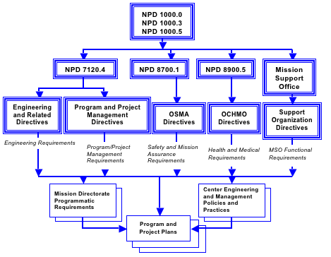
Figure 1-1 - Hierarchy of Related Documents
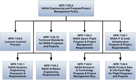
Figure 1-2 - Documentation Relationships
1.3.1. The common systems engineering framework consists of three elements that make up NASA systems engineering capability. The relationship of the three elements is illustrated in Figure 1-3. The integrated implementation of the three elements of the SE Framework is intended to improve the overall capability required for the efficient and effective engineering of NASA systems. The SE processes are one element of the larger context to produce quality products and achieve mission success. This NPR addresses the SE processes. The larger SE framework also includes the workforce and tools and methods. Additional initiatives to address these other elements include revision of the NASA handbook on systems engineering and development of tools and an assessment model. Together, these elements comprise the capability of an organization to perform successful SE. Each element is described below.
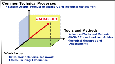
Figure 1 3 - SE Framework
1.3.2. Element 1: Common Technical Processes. The common technical processes of this NPR provide what has to be done to engineer system products within a project and why. These processes are applied to the hardware, software, and human systems integration of a system as one integrated whole. In addition to the common technical processes, contributions to improvements of SE capability also come from the inclusion of:
a. Concepts and terminology that are basic to consistent application and communication of the common technical processes Agency wide.
b. A structure for when the common technical processes are applied.
1.3.3. Element 2: Tools and Methods. Tools and methods enable the efficient and effective completion of the activities and tasks of the common technical processes. An essential contribution of this element to SE capability is the improvement of the engineering infrastructure through the three Agency-wide activities listed below:
a. Infusion of advanced methods and tools in the SE processes to achieve greater efficiency, collaboration, and communication among distributed teams.
b. Provision of a NASA handbook on SE methodologies (NASA/SP-2007-6105, NASA Systems Engineering Handbook) that is a source for various methods and procedures that Centers can draw upon to plan implementation of the required processes in their projects.
c. Measurement of the SE capability of projects within NASA and assessment of the improvements of capability resulting from implementation of the SE NPR, use of adopted methods and tools, and workforce engineering training.
1.3.4. Element 3: Workforce. A well-trained, knowledgeable, and experienced technical workforce is essential for improving SE capability. The workforce must be able to apply NASA and Center methods and tools for the completion of the required SE processes within the context of the program or project to which they are assigned. In addition, they must be able to effectively communicate requirements and solutions to customers, other engineers, and management to work efficiently and effectively on a team. Issues of recruitment, retention, and training are aspects included in this element. The OCE will facilitate the training of the NASA workforce on the application of this and associated NPRs.
1.4.1 This SE NPR is organized into the following chapters:
a. The Preface describes items such as the purpose, applicability, authority, and applicable documents of this SE NPR.
b. Chapter 1 (Introduction) describes the SE framework and document organization.
c. Chapter 2 describes the institutional and programmatic requirements, including roles and responsibilities. Tailoring of SE requirements and customization of SE practices are also addressed.
d. Chapter 3 describes the core set of common Agency-level technical processes and requirements for engineering NASA system products throughout the product life cycle. Appendix C contains supplemental amplifying material.
e. Chapter 4 describes the activities and requirements to be accomplished by assigned NASA technical teams or individuals (NASA employees and NASA support contractors) when performing technical oversight of a prime or other external contractor.
f. Chapter 5 describes the life-cycle and technical review requirements throughout the program and project life cycles. Appendix G contains entrance/success criteria guidance for each of the reviews.
g. Chapter 6 describes the Systems Engineering Management Plan, including the SEMP role, functions, and content. Appendix D provides details of a generic SEMP annotated outline.
2.1.1 General
The roles and responsibilities of senior management are defined in part in NPD 1000.0, NASA Governance and Strategic Management Handbook, and NPD 7120.4, NASA Engineering and Program/Project Management Policy. NPR 7120.5, NASA Space Flight Program and Project Management Requirements; NPR 7120.7, NASA Information Technology and Institutional Infrastructure Program and Project Management Requirements; NPR 7120.8, NASA Research and Technology Program and Project Management Requirements; and other NASA directives define the responsibilities of program and project managers. This NPR establishes systems engineering processes and responsibilities.
2.1.1.1 For programs and projects involving more than one Center, the lead organization will develop documentation for DGA approval to describe the hierarchy and reconciliation of Center plans implementing this NPR. The governing Mission Directorate or mission support office determines whether a Center executes a project in a lead role or in a supporting role. For Centers in supporting roles, compliance should be jointly negotiated and documented in the lead Center's project SEMP.
2.1.1.2 The roles and responsibilities associated with program and project management and Technical Authority (TA) are defined in the Program and Project Management NPRs (for example, NPR 7120.5 for space flight projects). Specific roles and responsibilities of the program/project manager and the engineering technical authority related to the SEMP are defined in Paragraphs 2.1.6 and 6.2.
2.1.2 Office of the Chief Engineer (OCE)
2.1.2.1 The OCE, under the authority of NPD 7120.4, will ensure compliance with this SE NPR.
2.1.2.2 The OCE will ensure systems engineering policies' compatibility across NASA.
2.1.3 Mission Directorate or Headquarters Program Offices
2.1.3.1 When programs and projects are managed at Headquarters or within Mission Directorates, that Program Office is responsible for the requirements in this NPR that are assigned to the Center Director. Technical teams residing at Headquarters will follow the requirements of this NPR unless specific process requirements have been established to implement this NPR by the governing organization. The technical teams residing at Centers will follow Center level process requirement documents.
2.1.4 Center Directors
2.1.4.1 In this document, the phrase "the Center Directors shall..." means the roles and responsibilities of the Center Directors may be further delegated within the organization to the scope and scale of the system.
2.1.4.2 The Center Director is responsible and accountable for both Institutional Authority responsibilities and the proper planning and execution of programs and projects assigned to the Center.
2.1.4.3 Center Directors shall perform the following activities:
a. Establish policies, procedures, and processes to execute the requirements of this SE NPR [SE-01].
b. Assess and take corrective actions to improve the execution of the requirements of this SE NPR [SE-02].
c. Select appropriate standards applicable to projects under their control [SE-03].
d. Complete the compliance matrix, as tailored, in Appendix H.1 for those requirements owned by the Office of Chief Engineer, and provide to the OCE upon request [SE-04].
2.1.5 Technical Teams
2.1.5.1 Each technical team executes the Center processes to implement this SE NPR under the oversight of the Center Directors in accordance with the SEMP. The makeup and organization of each technical team is the responsibility of each Center or program and includes the personnel required to implement the project.
2.1.5.2 For those requirements owned by Center Directors, the technical team shall complete the compliance matrix in Appendix H.2 and include it in the SEMP [SE-05].
2.1.5.3 For systems that contain software, the technical team ensures that software developed within NASA or acquired complies with NPR 7150.2, NASA Software Engineering Requirements.
Note 1: NPR 7150.2 elaborates on the requirements in this document and determines the applicability of requirements based on the Agency's software classification.
Note 2: NPD 7120.4 contains additional Agency requirements for the acquisition, development, maintenance, and management of software.
2.1.6 Designated Governing Authority
The Designated Governing Authority (DGA) for the technical effort in this SE NPR is the Center Director or the person that has been designated by the Center Director to ensure the appropriate level of technical management oversight. Such designation is made from the technical line so that independence between programmatic and technical authority is maintained. The DGA works with the Program/Project Manager to manage the technical effort. The DGA is assigned primary responsibility for evaluating the technical content of a particular program or project to ensure that it is meeting the commitments specified in the key technical management documents. The DGA shall approve the SEMP, waiver authorizations, and other key technical documents to ensure independent assessment of technical content [SE-06]. The DGA and the program/project manager approve the SEMP.
Note 1: For large programs/projects, the DGA will typically be the associated independently funded Engineering Technical Authority (ETA). In the case of very small projects, DGA responsibilities are occasionally delegated to line managers or other technical experts who are not independently funded and do not serve in an official ETA capacity. If the DGA is not a recognized ETA, an ETA at the appropriate level will be required to approve the SEMP to ensure compliance with the Agency's technical authority process.
Note 2: For NPR 7120.7 projects affecting more than one Center, the NASA Chief Information Officer (CIO) or the person the NASA CIO designates is the DGA.
2.2.1 Tailoring SE Requirements
2.2.1.1 SE requirements tailoring is the process used to seek relief from SE NPR requirements consistent with program or project objectives, acceptable risk, and constraints.
2.2.1.2 The tailoring process (which can occur at any time in the program or project's life cycle) results in deviations or waivers to requirements depending on the timing of the request. Deviations and waivers of the requirements in this NPR can be submitted separately to the requirements owner or via the appropriate compliance matrix in Appendix H.
2.2.1.3 The results of a Center's tailoring of NPR 7123.1 SE requirements will be documented in the Compliance Matrix for Centers (Appendix H.1) and submitted to OCE upon request or as changes to the Center processes occur.
2.2.1.4 The results of the program/project Technical Team tailoring of SE requirements from either NPR 7123.1 or a particular Center's implementation of NPR 7123.1, whichever is applicable, will be documented in the next revision of the SEMP, along with supporting rationale and documented approvals from the requirement owner.
2.2.1.5 The appropriate requirement owner, as described in the compliance matrices (Appendix H) will have responsibility to approve or disapprove any SE NPR requirement that is tailored.
2.2.2 Customization of SE Practices
2.2.2.1 Customization is the modification of recommended SE practices that are used to accomplish the SE requirements. Examples of these practices are in Appendix C or in NASA/SP-2007-6105.
2.2.2.2 Technical teams are encouraged to customize their non-requirement SE practices. The results of this customization do not require waivers or deviations, but significant customization should be documented in the SEMP.
2.2.3 Considerations for Tailoring or Customization
2.2.3.1 Considerations for tailoring or customization should include: scope and visibility (e.g., organizations and partnerships involved, international agreements); risk tolerance and failure consequences; system size; system complexity (e.g., human spaceflight vs. flagship science vs. subscale technology demonstration, number of stages and interfaces, technology readiness level); impact on other systems; longevity; serviceability (including on-orbit); constraints (including cost, schedule, degree of insight/oversight permitted with partnerships or international agreements, etc.); safety; technology base; and industrial base.
3.1.1 This chapter establishes the core set of common technical processes and requirements to be used by NASA projects in engineering system products during all life-cycle phases to meet phase exit criteria and project objectives. The 17 common technical processes are enumerated according to their description in this chapter and their interactions shown in Figure 3-1. This SE common technical processes model illustrates the use of: (1) the system design processes for "top-down" design of each product in the system structure; (2) the product realization processes for "bottom-up" realization of each product in the system structure; and (3) the cross-cutting technical management processes for planning, assessing, and controlling the implementation of the system design and product realization processes and to guide technical decision making (decision analysis). The SE common technical processes model is referred to as an "SE engine" in this SE NPR to stress that these common technical processes are used to drive the development of the system products and associated work products required by management to satisfy the applicable product life-cycle phase exit criteria while meeting stakeholder expectations within cost, schedule, and risk constraints.
3.1.2 This chapter identifies the following for each of the 17 common technical processes:
a. The specific requirement for Center Directors or designees to establish and maintain the process;
b. A brief description of how the process is used as an element of the Systems Engineering Engine; and
c. A reference to typical practices for the process as identified in Appendix C.
3.1.3 It should be emphasized that the Practices for Common Technical Processes documented in Appendix C do not represent additional requirements that must be implemented by the technical team. Appendix C is provided as a summary of typical best practices associated with the 17 common technical processes. As such, it should be considered in conjunction with other sources of systems engineering guidance such as NASA/SP-2007-6105, NASA Systems Engineering Handbook, as the technical team develops a customized approach for the application of these processes consistent with requirements implemented by Center documentation.
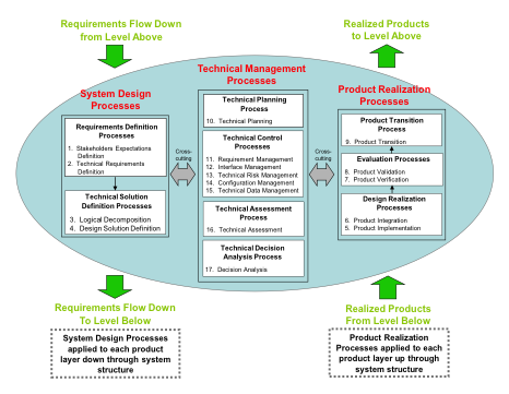
Figure 3 1 - Systems Engineering (SE) Engine
3.1.4 The context in which the common technical processes are used is provided below:
3.1.4.1 The common technical processes are applied to each product layer to concurrently develop the products that will satisfy the operational or mission functions of the system (end products) and that will satisfy the life-cycle support functions of the system (enabling products). In this document, product layer is defined as the product breakdown hierarchy that includes both the end product and enabling product hierarchy. The enabling products facilitate the activities of system design, product realization, operations and mission support, sustainment, and end-of-product-life disposal or recycling, by having the products and services available when needed.
3.1.4.2 The common technical processes are applied to design a system solution definition for each product layer down and across each level of the system structure and to realize the product layer end products up and across the system structure. Figure 3-2 illustrates how the three major sets of processes of the Systems Engineering (SE) Engine (system design processes, product realization processes, and technical management processes) are applied to each product layer within a system structure.
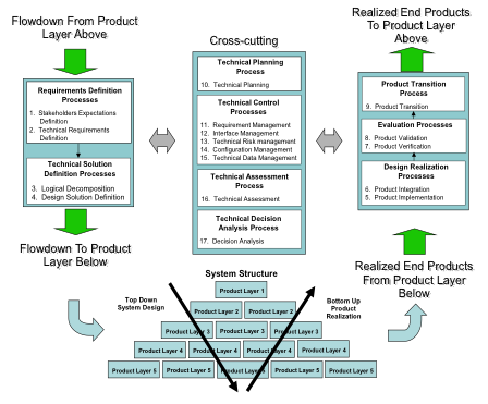
Figure 3-2 - Application of SE Engine Common Technical Processes
Within System Structure
3.1.4.3 The common technical processes are used to define the product layers of the system structure in each applicable phase of the relevant life cycle to generate work products and system products needed to satisfy the exit criteria of the applicable phase.
3.1.4.4 The common technical processes are applied by assigned technical teams and individuals trained in the requirements of this SE NPR.
3.1.4.5 The assigned technical teams and individuals are using the appropriate and available sets of tools and methods to accomplish required common technical process activities. This includes the use of modeling and simulation as applicable to the product phase, location of the product layer in the system structure, and the applicable phase exit criteria.
3.2.1 For this section, "establish" means developing policy, work instructions, or procedures to implement process activities. "Maintain" includes planning the process, providing resources, assigning responsibilities, training people, managing configurations, identifying and involving stakeholders, and monitoring and controlling the process. The technical team is responsible for the execution of these 17 required processes per Paragraph 2.1.5.
3.2.2 Stakeholder Expectations Definition Process
3.2.2.1 Center Directors or designees shall establish and maintain a Stakeholder Expectations Definition process to include activities, requirements, guidelines, and documentation for the definition of stakeholder expectations for the applicable product layer [SE-07].
3.2.2.2 The stakeholder expectations definition process is used to elicit and define use cases, scenarios, concept of operations, and stakeholder expectations for the applicable product life- cycle phases and product layer. This includes expectations such as: (a) operational end products and life-cycle-enabling products of the product layer; (b) affordability; (c) operator or user interfaces; (d) expected skills and capabilities of operators or users; (e) expected number of simultaneous users; (f) system and human performance criteria; (g) technical authority, standards, regulations, and laws; (h) factors such as health and safety, planetary protection, orbital debris, quality, security, context of use by humans, reliability, availability, maintainability, electromagnetic compatibility, interoperability, testability, transportability, supportability, usability, and disposability; and (i) local management constraints on how work will be done (e.g., operating procedures). The baselined stakeholder expectations are used for validation of the product layer end product during product realization. At this point, Measures of Effectiveness (MOEs) are defined.
3.2.2.3 Typical practices of this process are defined in Appendix C.1.1.
3.2.3 Technical Requirements Definition Process
3.2.3.1 Center Directors or designees shall establish and maintain a Technical Requirements Definition process to include activities, requirements, guidelines, and documentation for the definition of technical requirements from the set of agreed upon stakeholder expectations for the applicable product layer [SE-08].
3.2.3.2 The technical requirements definition process is used to transform the baselined stakeholder expectations into unique, quantitative, and measurable technical requirements expressed as "shall" statements that can be used for defining a design solution for the product layer end product and related enabling products. This process also includes validation of the requirements to ensure that the requirements are well-formed (clear and unambiguous), complete (agrees with customer and stakeholder needs and expectations), consistent (conflict free), and individually verifiable and traceable to a higher level requirement or goal. As part of this process, Measures of Performance (MOPs) and Technical Performance Measures (TPMs) are defined.
3.2.3.3 Typical practices of this process are defined in Appendix C.1.2.
3.2.4 Logical Decomposition Process
3.2.4.1 Center Directors or designees shall establish and maintain a Logical Decomposition process to include activities, requirements, guidelines, and documentation for logical decomposition of the validated technical requirements of the applicable product layer [SE-09].
3.2.4.2 The logical decomposition process is used to improve understanding of the defined technical requirements and the relationships among the requirements (e.g., functional, behavioral, performance, and temporal) and to transform the defined set of technical requirements into a set of logical decomposition models and their associated set of derived technical requirements for lower levels of the system and for input to the design solution definition process.
3.2.4.3 Typical practices of this process are defined in Appendix C.1.3.
3.2.5 Design Solution Definition Process
3.2.5.1 Center Directors or designees shall establish and maintain a Design Solution Definition process to include activities, requirements, guidelines, and documentation for designing product solution definitions within the applicable product layer that satisfy the derived technical requirements [SE-10].
3.2.5.2 The design solution definition process is used to translate the outputs of the logical decomposition process into a design solution definition that is in a form consistent with the product life-cycle phase and product layer location in the system structure and that will satisfy phase exit criteria. This includes transforming the defined logical decomposition models and their associated sets of derived technical requirements into alternative solutions, then analyzing each alternative to be able to select a preferred alternative, and fully defining that alternative into a final design solution definition that will satisfy the requirements.
3.2.5.3 These design solution definitions will be used for generating end products either by using the product implementation process or product integration process as a function of the position of the product layer in the system structure and whether there are additional subsystems of the end product that need to be defined. The output definitions from the design solution (end product specifications) will be used for conducting product verification.
3.2.5.4 Typical practices of this process are defined in Appendix C.1.4.
3.2.6 Product Implementation Process
3.2.6.1 Center Directors or designees shall establish and maintain a Product Implementation process to include activities, requirements, guidelines, and documentation for implementation of a design solution definition by making, buying, or reusing an end product of the applicable product layer [SE-11].
3.2.6.2 The product implementation process is used to generate a specified product of a product layer through buying, making, or reusing in a form consistent with the product life-cycle phase exit criteria and that satisfies the design solution definition (e.g., drawings, specifications).
3.2.6.3 Typical practices of this process are defined in Appendix C.2.1.
3.2.7 Product Integration Process
3.2.7.1 Center Directors or designees shall establish and maintain a Product Integration process to include activities, requirements, guidelines, and documentation for the integration of lower level products into an end product of the applicable product layer in accordance with its design solution definition [SE-12].
3.2.7.2 The product integration process is used to transform lower level, validated end products into the desired end product of the higher level product layer through assembly and integration.
3.2.7.3 Typical practices of this process are defined in Appendix C.2.2.
3.2.8 Product Verification Process
3.2.8.1 Center Directors or designees shall establish and maintain a Product Verification process to include activities, requirements/specifications, guidelines, and documentation for verification of end products generated by the product implementation process or product integration process against their design solution definitions [SE-13].
3.2.8.2 The product verification process is used to demonstrate that an end product generated from product implementation or product integration conforms to its design solution definition requirements as a function of the product life-cycle phase and the location of the product layer end product in the system structure. Special attention is given to demonstrating satisfaction of the MOPs defined for each MOE during conduct of the technical requirements definition process.
3.2.8.3 Typical practices of this process are defined in Appendix C.2.3.
3.2.9 Product Validation Process
3.2.9.1 Center Directors or designees shall establish and maintain a Product Validation process to include activities, requirements, guidelines, and documentation for validation of end products generated by the product implementation process or product integration process against their stakeholder expectations [SE-14].
3.2.9.2 The product validation process is used to confirm that a verified end product generated by product implementation or product integration fulfills (satisfies) its intended use when placed in its intended environment and to ensure that any anomalies discovered during validation are appropriately resolved prior to delivery of the product (if validation is done by the supplier of the product) or prior to integration with other products into a higher level assembled product (if validation is done by the receiver of the product). The validation is done against the set of baselined stakeholder expectations. Special attention should be given to demonstrating satisfaction of the MOEs identified during conduct of the stakeholder expectations definition process. The type of product validation is a function of the form of the product and product life-cycle phase and in accordance with an applicable customer agreement.
3.2.9.3 Typical practices of this process are defined in Appendix C.2.4.
3.2.10 Product Transition Process
3.2.10.1 Center Directors or designees shall establish and maintain a Product Transition process to include activities, requirements, guidelines, and documentation for transitioning end products to the next higher level product layer customer or user [SE-15].
3.2.10.2 The product transition process is used to transition a verified and validated end product that has been generated by product implementation or product integration to the customer at the next level in the system structure for integration into an end product or, for the top level end product, transitioned to the intended end user. The form of the product transitioned will be a function of the product life-cycle phase and the location within the system structure of the product layer in which the end product exists.
3.2.10.3 Typical practices of this process are defined in Appendix C.2.5.
3.2.11 Technical Planning Process
3.2.11.1 Center Directors or designees shall establish and maintain a Technical Planning process to include activities, requirements, guidelines, and documentation for planning the technical effort [SE-16].
3.2.11.2 The technical planning process is used to plan for the application and management of each common technical process. It is also used to identify, define, and plan the technical effort applicable to the product life-cycle phase for product layer location within the system structure and to meet project objectives and product life-cycle phase exit criteria. A key document generated by this process is the SEMP (See Chapter 6).
3.2.11.3 Typical practices of this process are defined in Appendix C.3.1.
3.2.12 Requirements Management Process
3.2.12.1 Center Directors or designees shall establish and maintain a Requirements Management process to include activities, requirements, guidelines, and documentation for management of requirements throughout the system life cycle [SE-17].
3.2.12.2 The requirements management process is used to: (a) manage the product requirements identified, baselined, and used in the definition of the product layer products during system design; (b) provide bidirectional traceability back to the top product layer requirements; and (c) manage the changes to established requirement baselines over the life cycle of the system products.
3.2.12.3 Typical practices of this process are defined in Appendix C.3.2.
3.2.13 Interface Management Process
3.2.13.1 Center Directors or designees shall establish and maintain an Interface Management process to include activities, requirements, guidelines, and documentation for management of the interfaces defined and generated during the application of the system design processes [SE-18].
3.2.13.2 The interface management process is used to: (a) establish and use formal interface management to assist in controlling system product development efforts when the efforts are divided between Government programs, contractors, and/or geographically diverse technical teams within the same program or project; and (b) maintain interface definition and compliance among the end products and enabling products that compose the system, as well as with other systems with which the end products and enabling products must interoperate.
3.2.13.3 Typical practices of this process are defined in Appendix C.3.3.
3.2.14 Technical Risk Management Process
3.2.14.1 Center Directors or designees shall establish and maintain a Technical Risk Management process to include activities, requirements, guidelines, and documentation for management of the risk identified during the technical effort [SE-19].
3.2.14.2 The technical risk management process is used to make risk-informed decisions and examine, on a continuing basis, the potential for deviations from the project plan and the consequences that could result should they occur. This enables risk-handling activities to be planned and invoked as needed across the life of the product or project to mitigate impacts on achieving product life-cycle phase exit criteria and meeting technical objectives. The technical team supports the development of potential health and safety, cost, and schedule impacts for identified technical risks and any associated mitigation strategies. NPR 8000.4, Agency Risk Management Procedural Requirements, is to be used as a source document for defining this process and NPR 8705.5, Technical Probabilistic Risk Assessment (PRA) Procedures for Safety and Mission Success for NASA Programs and Projects, provides one means of identifying and assessing technical risk. While the focus of this requirement is the management of technical risk, the process applies to the management of programmatic risks as well. The highly interdependent nature of health and safety, technical, cost, and schedule risks require the broader program/project team to consistently address risk management with an integrated approach. NASA/SP-2011-3422, NASA Risk Management Handbook, provides guidance for managing risk in an integrated fashion.
3.2.14.3 Typical practices of this process are defined in Appendix C.3.4.
3.2.15 Configuration Management Process
3.2.15.1 Center Directors or designees shall establish and maintain a Configuration Management process to include activities, requirements, guidelines, and documentation for configuration management [SE-20].
3.2.15.2 The configuration management process for end products, enabling products, and other work products placed under configuration control is used to: (a) identify the configuration of the product or work product at various points in time; (b) systematically control changes to the configuration of the product or work product; (c) maintain the integrity and traceability of the configuration of the product or work product throughout its life; and (d) preserve the records of the product or end product configuration throughout its life cycle, dispositioning them in accordance with NPR 1441.1, NASA Records Retention Schedules.
3.2.15.3 Typical practices of this process are defined in Appendix C.3.5.
3.2.16 Technical Data Management Process
3.2.16.1 Center Directors or designees shall establish and maintain a Technical Data Management process to include activities, requirements, guidelines, and documentation for management of the technical data generated and used in the technical effort [SE-21].
3.2.16.2 The technical data management process is used to plan for, acquire, access, manage, protect, and use data of a technical nature to support the total life cycle of a system. This process is used to capture trade studies, cost estimates, technical analyses, reports, and other important information.
3.2.16.3 Typical practices of the technical data management process are defined in Appendix C.3.6.
3.2.17 Technical Assessment Process
3.2.17.1 Center Directors or designees shall establish and maintain a Technical Assessment process to include activities, requirements, guidelines, and documentation for making assessments of the progress of planned technical effort and progress toward requirements satisfaction [SE-22].
3.2.17.2 The technical assessment process is used to help monitor progress of the technical effort and provide status information for support of the system design, product realization, and technical management processes. A key aspect of the technical assessment process is the conduct of life-cycle and technical reviews throughout the system life cycle in accordance with Chapter 5.
3.2.17.3 Typical practices of this process are defined in Appendix C.3.7.
3.2.18 Decision Analysis Process
3.2.18.1 Center Directors or designees shall establish and maintain a Decision Analysis process to include activities, requirements, guidelines, and documentation for making technical decisions [SE-23].
3.2.18.2 The decision analysis process, including processes for identification of decision criteria, identification of alternatives, analysis of alternatives, and alternative selection, is applied to technical issues to support their resolution. It considers relevant data (e.g., engineering performance, quality, and reliability) and associated uncertainties. Decision analysis is used throughout the system life cycle to formulate candidate decision alternatives and evaluate their impacts on health and safety, technical, cost, and schedule performance. NASA/SP-2010-576, NASA Risk-informed Decision Making Handbook, provides guidance for analyzing decision alternatives in a risk-informed fashion.
3.2.18.3 Typical practices of this process are defined in Appendix C.3.8.
4.1.1 Oversight/insight of projects where prime or other external contractors do the majority of the development effort has always been an important part of NASA programs and projects. "Insight" is a monitoring activity, whereas "oversight" is an exercise of authority by the Government. The Federal Acquisition Regulation and the NASA Supplement to the Federal Acquisition Regulation govern the acquisition planning, contract formation, and contract administration process. Authority to interface with the contractor can only be delegated by the contracting officer. The activities listed in Paragraph 4.2 will be coordinated with the cognizant contracting officer. Detailed definitions for insight and oversight are provided in the NASA Federal Acquisition Regulation Supplement, subpart 1846.4, Government Contract Quality Assurance.
4.1.2 This chapter defines a minimum set of technical activities and requirements for a NASA project technical team to perform before contract award, during contract performance, and upon completion of the contract on projects where prime or external contractors do the majority of the development effort. These activities and requirements are intended to supplement the common technical process activities and requirements of Chapter 3 and thus enhance the outcome of the contracted effort.
4.2.1 The NASA technical team shall define the engineering activities for the periods before contract award, during contract performance, and upon contract completion in the SEMP [SE-24]. The content of Appendix D should be used as a guide.
4.2.2 The NASA technical team shall use common technical processes, as implemented by the Center's documentation, to establish the technical inputs to the Request for Proposal (RFP) appropriate for the product to be developed, including product requirements and Statement of Work tasks [SE-25].
4.2.3 The NASA technical team shall determine the technical work products to be delivered by the offeror or contractor, to include a contractor SEMP that specifies the contractor's systems engineering approach for requirements development; technical solution definition; design realization; product evaluation; product transition; and technical planning, control, assessment, and decision analysis [SE-26].
4.2.4 The NASA technical team shall provide the requirements for technical insight and oversight activities planned in the NASA SEMP to the contracting officer for inclusion in the RFP [SE-27].
Note: Care should be taken that no requirements or solicitation information is divulged prior to the release of the solicitation by the contracting officer.
4.2.5 The NASA technical team shall have representation in the evaluation of offeror proposals in accordance with applicable NASA and Center source selection procedures [SE-28].
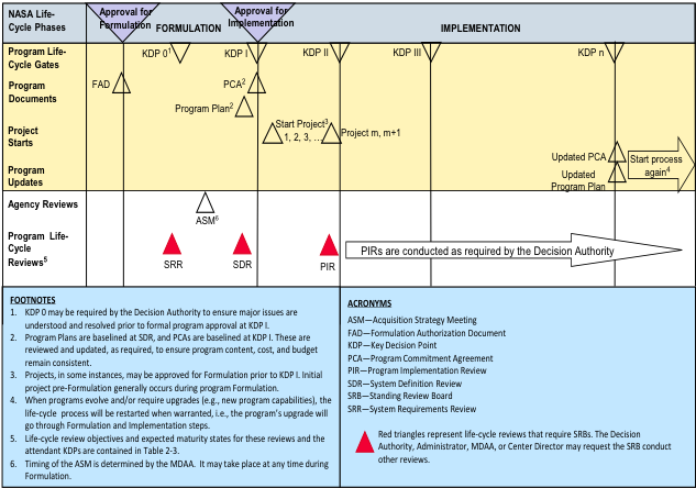
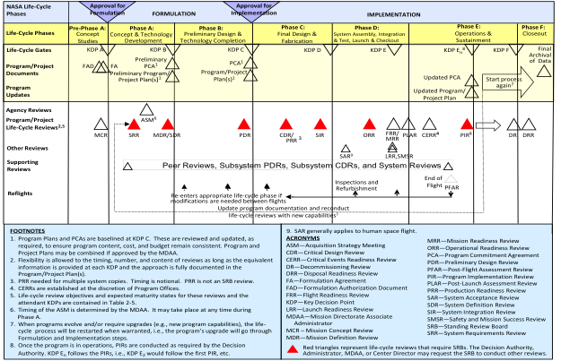
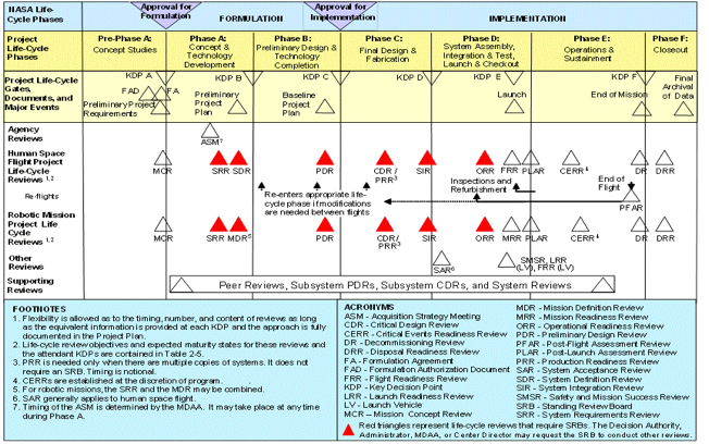
5.1.1 NASA defines four types of programs that may contain projects: (1) uncoupled programs; (2) loosely coupled programs; (3) tightly coupled programs; and (4) single-project programs. Which life cycle a program/project uses will be dependent on what type of program/project it is and whether the program/project is producing products for space flight, advanced development, information technology, construction of facilities, or other applications. A specific life cycle may be required by associated project management NPRs. For example, NPR 7120.5 defines the life cycles for space flight programs and projects. NPR 7120.7 defines life cycles for IT and institutional program/projects. For Announcement of Opportunity (AO) driven projects, refer to NPR 7120.5, Paragraph 2.2.7.1. For purposes of illustration, life cycles from NPR 7120.5 are repeated here in Figures 5-1 through 5-4.
5.1.2 The application of the common technical processes within each life-cycle phase produces technical results that provide inputs to life-cycle and technical reviews and support informed management decisions for progressing to the next life-cycle phase.
5.1.3 Each program and project will perform the life-cycle reviews as required by their governing project management NPR, applicable Center practices, and the requirements of this document. These reviews provide a periodic assessment of the program's or project's technical and programmatic status and health at key points in the life cycle. The technical team provides the technical inputs to be incorporated into the overall program/project review package. Appendix G provides guidelines for the entrance and exit criteria for each of these reviews with a focus on the technical products. Additional programmatic products may also be required by the governing program/project NPR. Programs/projects are expected to customize the entrance/exit criteria as appropriate to the size/complexity and unique needs of their activities.
5.1.4 The progress between life-cycle phases is marked by key decision points (KDPs). At each KDP, management examines the maturity of the technical aspects of the project. For example, management examines whether the resources (staffing and funding) are sufficient for the planned technical effort, whether the technical maturity has evolved, what the technical and nontechnical internal issues and risks are, and whether the stakeholder expectations have changed. If the technical and management aspects of the project are satisfactory, including the implementation of corrective actions, then the project can be approved to proceed to the next phase. Program and Project Management NPRs (NPR 7120.5, NPR 7120.7, and NPR 7120.8) contain further details relating to life-cycle progress.
Note: For example only. Refer to NPR 7120.5 for the official life cycle. Table 2-3 in the above references is in NPR 7120.5.
Figure 5 1 - NASA Uncoupled and Loosely Coupled Program Life Cycle
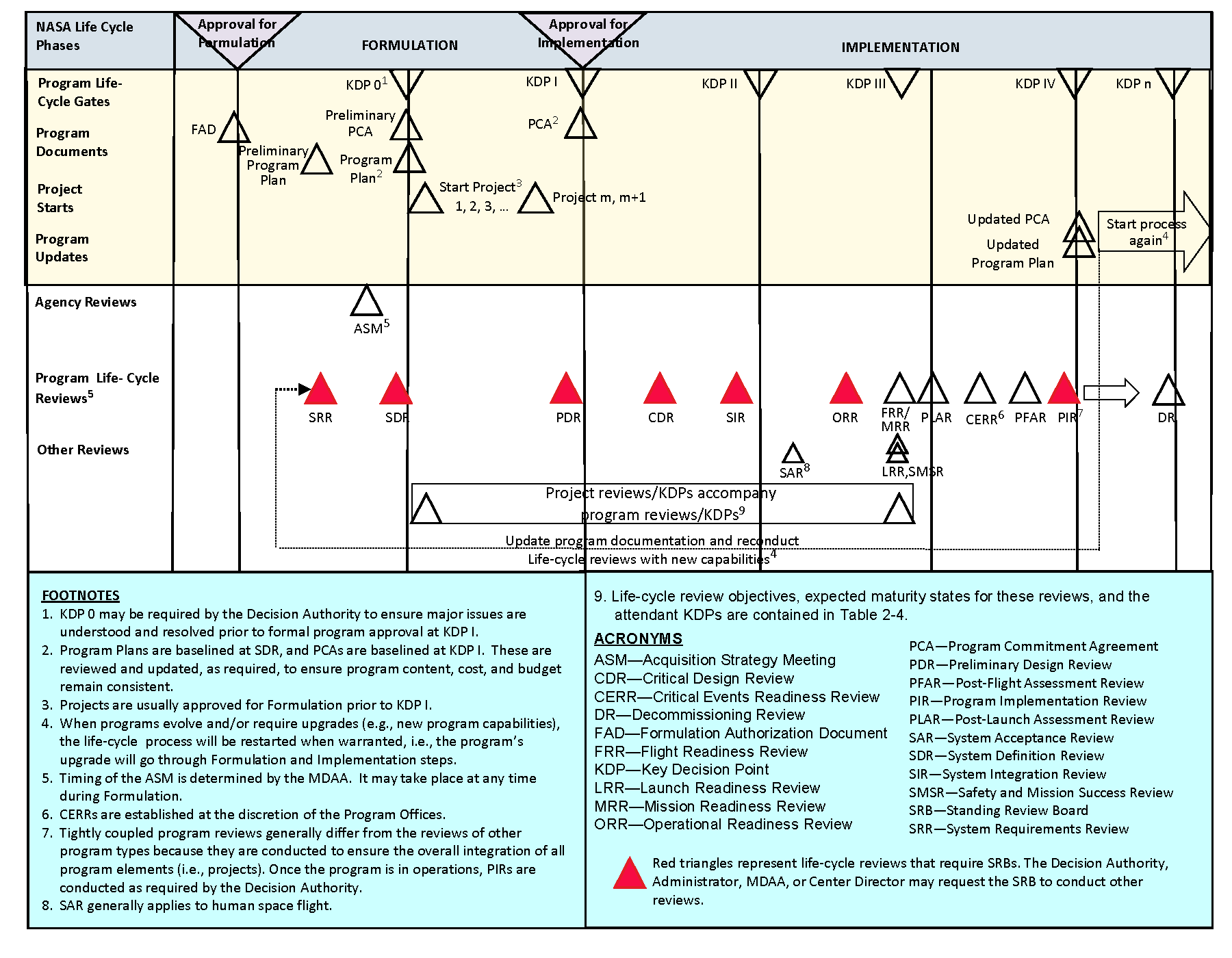
Note: For example only. Refer to NPR 7120.5 for the official life cycle. Table 2-3 in the above references is in NPR 7120.5.
Figure 5-2 - NASA Tightly Coupled Program Life Cycle
Note: For example only. Refer to NPR 7120.5 for the official life cycle. Table 2-3 in the above references is in NPR 7120.5.
Figure 5-3 - NASA Single-Project Program Life Cycle
Note: For example only. Refer to NPR 7120.5 for the official life cycle. Table 2-3 in the above references is in NPR 7120.5.
Figure 5 4 - The NASA Project Life Cycle
5.1.5 Life-cycle reviews are event based and occur when the entrance criteria for the applicable review are satisfied. (Appendix G provides guidance.) They occur based on the maturity of the relevant technical baseline as opposed to calendar milestones (e.g., the quarterly progress review, the yearly summary).
5.1.6 Accurate assessment of technology maturity is critical to technology advancement and its subsequent incorporation into operational products. The program/project ensures that Technology Readiness Levels (TRLs) and/or other measures of technology maturity are used to assess maturity throughout the life cycle of the project. When other measures of technology maturity are used, they should be mapped back to TRLs. The definition of the TRLs for hardware and software are defined in Appendix E. Moving to higher levels of maturity requires an assessment of a range of capabilities for design, analysis, manufacture, and test. Measures for assessing technology maturity are described in NASA/SP-2007-6105, NASA Systems Engineering Handbook. The initial maturity assessment is done in the Formulation phase and updated at project status reviews.
5.2.1 Planning and Conduct
5.2.1.1 The technical team shall develop and document plans for life-cycle and technical reviews for use in the project planning process [SE-32]. The life-cycle and technical review schedule, as documented in the SEMP, will be reflected in the overall project plan. The results of each life-cycle and technical review will be used to update the technical review plan as part of the SEMP update process. The review plans, data, and results should be maintained and dispositioned as Federal records.
5.2.1.2 The technical team ensures that system aspects represented or implemented in software are included in all life-cycle and technical reviews to demonstrate that project technical goals and progress are being achieved and that all software review requirements are implemented. Software review requirements are provided in NPR 7150.2, with guidance provided in NASA-HDBK-2203, NASA Software Engineering Handbook.
5.2.1.3 The technical team shall conduct the life-cycle and technical reviews as indicated in the governing project management NPR [SE-33]. Additional description of technical reviews is provided in NASA/SP-2007-6105, NASA Systems Engineering Handbook. (For requirements on program and project life cycles and management reviews, see the appropriate NPR, e.g., NPR 7120.5.)
5.2.1.4 The technical team shall participate in the development of entrance and success criteria for each of the respective reviews [SE-34]. The technical team should utilize the best practices defined in Appendix G as well as Center best practices for defining entrance and success criteria.
5.2.1.5 The technical team shall provide the following minimum products at the associated milestone review at the indicated maturity level:
a. Mission Concept Review (MCR):
(1) Baselined stakeholder identification and expectation definitions [SE-35].
(2) Baselined concept definition [SE-36].
(3) Approved MOE definition [SE-37].
b. System Requirements Review (SRR):
(1) Baselined SEMP for projects, single-project programs, and one-step AO programs [SE-38].
(2) Baselined requirements [SE-39].
c. Mission Definition Review/System Definition Review (MDR/SDR):
(1) Approved TPM definitions [SE-40].
(2) Baselined architecture definition [SE-41].
(3) Baselined allocation of requirements to next lower level [SE-42].
(4) Initial trend of required leading indicators [SE-43].
(5) Baseline SEMP for uncoupled, loosely coupled, tightly coupled, and two-step AO programs [SE-44].
d. Preliminary Design Review (PDR):
(1) Preliminary design solution definition [SE-45].
e. Critical Design Review (CDR):
(1) Baseline detailed design [SE-46].
f. System Integration Review (SIR):
(1) Updated integration plan [SE-47].
(2) Preliminary verification and validation (VandV) results [SE-48].
g. Operational Readiness Review (ORR):
(1) Updated operational plans [SE-49].
(2) Updated operational procedures [SE-50].
(3) Preliminary decommissioning plans [SE-51].
h. Flight Readiness Review (FRR):
(1) Baseline disposal plans [SE-52].
(2) Baseline VandV results [SE-53].
(3) Final certification for flight/use [SE-54].
i. Decommissioning Review (DR):
(1) Baseline decommissioning plans [SE-55].
j. Disposal Readiness Review (DRR):
(1) Updated disposal plans [SE-56].
5.2.1.6 Table 5-1 shows the maturity of primary SE products at the associated milestone reviews for all types and sizes of programs/projects. The required SE products identified above are highlighted in blue in the table. For further description of the primary SE products, refer to Appendix G. For additional guidance on software product maturity for project life-cycle reviews, refer to NASA-HDBK-2203, NASA Software Engineering Handbook. Additional programmatic products are required by the governing program/project management NPRs, but not listed herein.
5.2.1.7 The expectation for products identified as "baselined" in Paragraph 5.2.1.5 and Table 5-1 is that they will be at least final drafts going into the designated life-cycle review. Subsequent to the review, the final draft will be updated in accordance with approved review comments, Review Item Discrepancies, or Requests for Action and formally baselined.
5.2.1.8 Terms for maturity levels of technical products identified in this section are addressed in detail in Appendix F.
5.2.1.9 The technical team ensures that each program or project hosting equipment, experiments, or payloads with radio frequency (RF) requirements include success criteria in all life-cycle and technical reviews to receive approval from the responsible Center spectrum manager that program or project spectrum goals and progress are being achieved and satisfy all spectrum regulatory requirements. Spectrum certification requirements are provided in NPD 2570.5 and NPR 2570.1. NPR 2570.1 takes precedence over this document regarding spectrum related procedures and processes.
Table 5-1 - SE Product Maturity
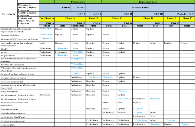
** Item is a required product for that review.
1For projects, single-project programs, and one-step AO programs.
2For uncoupled, tightly coupled, loosely coupled programs, and two-step AO programs.
5.2.2 Review Process and Practices
5.2.2.1 For each type of program/project, technical efforts are monitored throughout the life cycle to ensure that the technical goals of the project are being achieved and that the technical direction of the project is appropriate.
5.2.2.2 Technical teams shall monitor technical effort through periodic technical status reviews [SE-57].
5.2.2.3 A technical status review is an evaluation of the project, or element thereof, by the technical team and other knowledgeable participants for the purposes of:
a. Assessing the status of and progress toward accomplishing the planned activities.
b. Validating the technical tradeoffs explored and design solutions proposed.
c. Identifying technical weaknesses or marginal design and potential problems (risks) and recommending improvements and corrective actions.
d. Making judgments on the activities' readiness for the follow-on events, including additional future evaluation milestones to improve the likelihood of a successful outcome.
e. Making assessments and recommendations to the project team, Center, and Agency management.
f. Providing a historical record of decisions that were made during these formal reviews which can be referenced at a later date.
g. Assessing the technical risk status and current risk profile.
5.3.1 Reviews are considered complete when the following are accomplished:
a. Agreement exists for the disposition of all Review Item Discrepancies (RIDs) and Request for Actions (RFAs).
b. The review board report and minutes are complete and distributed.
c. Agreement exists on a plan to address the issues and concerns in the review board's report.
d. Agreement exists on a plan for addressing the actions identified out of the review.
e. Liens against the review results are closed, or an adequate and timely plan exists for their closure.
f. Differences of opinion between the project under review and the review board(s) have been resolved, or a timely plan exists to resolve the issues.
g. A report is given by the review board chairperson to the appropriate management and governing program management committees (PMCs) charged with oversight of the project.
h. Appropriate procedures and controls are instituted to ensure that all actions from reviews are followed and verified through implementation to closure.
i. The Program/Project Decision Authority signs a decision memo documenting successful completion of the review.
6.1.1 A Systems Engineering Management Plan (SEMP) is used to establish the technical content of the engineering work early in the Formulation phase for each project and updated as needed throughout the project life cycle. The SEMP provides the specifics of the technical effort and describes what technical processes will be used, how the processes will be applied using appropriate activities, how the project will be organized to accomplish the activities, and the resources required for accomplishing the activities. The process activities are driven by the critical events during any phase of a life cycle (including operations) that set the objectives and work product outputs of the processes and how the processes are integrated. (See Appendix D for an annotated outline for the SEMP.) The SEMP provides the communication bridge between the project management team and the technical implementation teams. It also facilitates effective communication within the technical teams. The SEMP provides the framework to realize the appropriate work products that meet the entry and exit criteria of the applicable project life-cycle phases to provide management with necessary information for assessing technical progress.
6.1.2 The primary function of the SEMP is to provide the basis for implementing the technical effort and communicating what will be done and by whom, when, where, cost drivers, and why it is being done. In addition, the SEMP identifies the roles and responsibility interfaces of the technical effort and how those interfaces will be managed.
6.1.3 The SEMP is the vehicle that documents and communicates the technical approach, including the application of the common technical processes; resources to be used; and key technical tasks, activities, and events along with their metrics and success criteria. The SEMP communicates the technical effort that will be performed by the assigned technical team to the team itself, managers, customers, and other stakeholders. Whereas the primary focus is on the applicable phase in which the technical effort will be done, the planning extends to a summary of the technical efforts that are planned for future applicable phases.
6.1.4 The SEMP is a tailorable document that captures a project's current and evolving systems engineering strategy and its relationship with the overall project management effort throughout the life cycle of the system. The SEMP's purpose is to guide all technical aspects of the project.
6.1.5 The SEMP is consistent with higher level SEMPs and the project plan.
6.1.6 The content of a SEMP for an in-house technical effort may differ from an external technical effort. For an external technical effort, the SEMP should include details on developing requirements for source selection, monitoring performance, and transferring and integrating externally produced products to NASA. (See Appendix D for further details.)
6.1.7 The SEMP provides the basis for generating the contractor engineering plan.
6.2.1 Working with the program/project manager, the technical team determines the appropriate level within the system structure at which SEMPs are to be developed, taking into account factors such as number and complexity of interfaces, operating environments, and risk factors.
6.2.2 The technical team establishes the initial SEMP early in the Formulation phase and updates it as necessary to reflect changes in scope or improved technical development.
6.2.3 The technical teams shall define in the project SEMP how the required 17 common technical processes, as implemented by Center documentation, including tailoring, will be recursively applied to the various levels of project product layer system structure during each applicable life-cycle phase [SE-58]. The technical teams will have their approaches approved by the Designated Governing Authority (DGA). (See SE Handbook).
6.2.4 The technical team baselines the SEMP per the Center's procedures and policies at SRR for projects and single-project programs and System Definition Review (SDR) for loosely coupled programs, tightly coupled programs, and uncoupled programs. The content of Appendix D should be used as a guide. At the discretion of the project manager and the DGA, for a small project the material in the SEMP can be placed in the project plan's technical summary and the annotated outline in Appendix D used as a topic guide.
6.2.5 As changes occur, the SEMP will be updated by the technical team, reviewed and reapproved by both the DGA and the program/project manager, and presented at subsequent milestone reviews or their equivalent. The SEMP is updated at major milestone reviews through the SIR.
6.2.6 The technical team shall ensure that any technical plans and discipline plans are consistent with the SEMP and are accomplished as fully integrated parts of the technical effort [SE-59].
6.2.7 The technical team shall establish Technical Performance Measures (TPMs) for the project that track/describe the current state versus plan [SE-60]. These measures are described in the SEMP per Appendix D.
6.2.8 The technical team shall report the TPMs to the program/project manager on an agreed-to reporting interval [SE-61].
6.2.9 A technical leading indicator is a subset of the TPMs that provides insight into the potential future states. The technical team shall ensure that the set of TPMs include the following leading indicators:
a. Mass margins for projects involving hardware [SE-62].
b. Power margins for projects that are powered [SE-63].
6.2.10 The technical team shall ensure that the set of Review Trends includes closure of review action documentation (Request for Action, Review Item Discrepancies, and/or Action Items as established by the project) for all software and hardware projects [SE-64].
Acceptable Risk: The risk that is understood and agreed to by the program/project, governing PMC, Mission Directorate, and other customer(s) such that no further specific mitigating action is required. (Some mitigating actions might have already occurred.)
Activity: A set of tasks that describe the technical effort to accomplish a process and help generate expected outcomes.
Affordability: The practice of balancing system performance and risk with cost and schedule constraints over the system life satisfying system operational needs in concert with strategic investment and evolving stakeholder value.
Approve (with respect to Technology Maturation Products from Appendix F): Used for a product, such as Concept Documentation, that is not expected to be put under classic configuration control but still requires that changes from the "approved" version are documented at each subsequent "update."
Baseline: An agreed-to set of requirements, designs, or documents that will have changes controlled through a formal approval and monitoring process.
Baseline (with respect to Technology Maturation Products from Appendix F): Indicates putting the product under configuration control so that changes can be tracked, approved, and communicated to the team and any relevant stakeholders. The expectation on products labeled "baseline" is that they will be at least final drafts going into the designated review and baselined coming out of the review. Baselining a product does not necessarily imply that it is fully mature at that point in the life cycle. Updates to baselined documents require the same formal approval process as the original baseline.
Bidirectional Traceability: The ability to trace any given requirement/expectation to its parent requirement/expectation and to its allocated children requirements/expectations.
Certification Package: The body of evidence that results from the verification activities and other activities such as reports, special forms, models, waivers, or other supporting documentation that is evaluated to indicate the design is certified for flight/use.
Component Facilities: Complexes that are geographically separated from the NASA Center or institution to which they are assigned but are still part of the Agency.
Concept of Operations (ConOps): Developed early in Pre-Phase A, describes the overall high-level concept of how the system will be used to meet stakeholder expectations, usually in a time sequenced manner. It describes the system from an operational perspective and helps facilitate an understanding of the system goals. It stimulates the development of the requirements and architecture related to the user elements of the system. It serves as the basis for subsequent definition documents and provides the foundation for the long-range operational planning activities.
Contractor: For the purposes of this NPR, an individual, partnership, company, corporation, association, or other service having a contract with the Agency for the design, development, manufacture, maintenance, modification, operation, or supply of items or services under the terms of a contract to a program or project within the scope of this NPR. Research grantees, research contractors, and research subcontractors are excluded from this definition.
Corrective Action: Action taken on a product to correct and preclude recurrence of a failure or anomaly, e.g., design change, procedure change, personnel training.
Critical Event: An event in the operations phase of the mission that is time sensitive and is required to be accomplished successfully in order to achieve mission success. These events must be considered early in the life cycle as drivers for system design.
Customer: The organization or individual that has requested a product and will receive the product to be delivered. The customer may be an end user of the product, the acquiring agent for the end user, or the requestor of the work products from a technical effort. Each product within the system hierarchy has a customer.
Customization: The modification of recommended SE practices that are used to accomplish the SE requirements. Examples of these practices are in Appendix C or in the NASA Systems Engineering Handbook, NASA/SP-2007-6105.
Decision Authority: The individual authorized by the Agency to make important decisions for programs and projects under their authority.
Derived Requirements: Requirements arising from constraints, consideration of issues implied but not explicitly stated in the high-level direction provided by Agency and Center institutional requirements, or factors introduced by the selected architecture and design.
Designated Governing Authority: The Center Director or the person that has been designated by the Center Director to ensure the appropriate level of technical management oversight. For large program/projects, this will usually be the identified Engineering Technical Authority. For small activities/projects, the DGA may be delegated to a line manager or other appropriate technical expert.
Deviation: A documented authorization releasing a program or project from meeting a requirement before the requirement is put under configuration control at the level the requirement will be implemented.
Documentation: Captured information and its support medium that is suitable to be placed under configuration control. Note that the medium may be paper, photograph, electronic storage (digital documents and models), or a combination.
Enabling Products: The life-cycle support products and services (e.g., production, test, deployment, training, maintenance, and disposal) that facilitate the progression and use of the operational end product through its life cycle. Since the end product and its enabling products are interdependent, they are viewed as a system. Project responsibility thus extends to responsibility for acquiring services from the relevant enabling products in each life-cycle phase. When a suitable enabling product does not already exist, the project that is responsible for the end product can also be responsible for creating and using the enabling product. An example is below in Figure A-1.
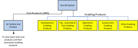
Figure A-1 - Enabling Product Relationship to End Products
Entrance Criteria: Guidance for minimum accomplishments each program or project fulfills prior to a life-cycle review
Establish (with respect to each process in Chapter 3): Develop policy, work instructions, or procedures to implement process activities.
Expectation: A statement of needs, desires, capabilities, and wants that are not expressed as a requirement (not expressed as a "shall" statement). Once the set of expectations from applicable stakeholders is collected, analyzed, and converted into a "shall" statement, the "expectation" becomes a "requirement." Expectations can be stated in either qualitative (nonmeasurable) or quantitative (measurable) terms. Requirements are always stated in quantitative terms. Expectations can be stated in terms of functions, behaviors, or constraints with respect to the product being engineered or the process used to engineer the product.
Federal Records: All books, papers, maps, photographs, machine-readable materials, or other documentary materials, regardless of physical form or characteristics, made or received by an agency of the U.S. Government under Federal law or in connection with the transaction of public business and preserved or appropriate for preservation by that agency or its legitimate successor as evidence of the organization, functions, policies, decisions, procedures, operations, or other activities of the Government or because of the informational value of the data in them.
Final (with respect to Technology Maturation Products from Appendix F): Applied to products that are expected to exist in a specified form, e.g., minutes and final reports.
Formulation Phase: The first part of the NASA management life cycle defined in NPR 7120.5, where system requirements are baselined, feasible concepts are determined, a system definition is baselined for the selected concept(s), and preparation is made for progressing to the Implementation phase.
Human Systems Integration: An interdisciplinary and comprehensive management and technical process that focuses on the integration of human considerations into the system acquisition and development processes to enhance human system design, reduce life-cycle ownership cost, and optimize total system performance. Human system domain design activities associated with manpower, personnel, training, human factors engineering, safety, health, habitability, and survivability are considered concurrently and integrated with all other systems engineering design activities.
Implementation Phase: The part of the NASA management life cycle defined in NPR 7120.5, where the detailed design of system products is completed and the products to be deployed are fabricated, assembled, integrated, and tested and the products are deployed to their customers or users for their assigned use or mission.
Initial (with respect to Technology Maturation Products from Appendix F): Applied to products that are continually developed and updated as the program or project matures.
Insight: An element of Government surveillance that monitors contractor compliance using Government-identified metrics and contracted milestones. Insight is a continuum that can range from low intensity, such as reviewing quarterly reports, to high intensity, such as performing surveys and reviews.
Institutional Projects (IP): Projects that build or maintain the institutional infrastructure to support the NASA missions.
Iterative: Application of a process to the same product or set of products to correct a discovered discrepancy or other variation from requirements. (See Recursive and Repeatable.)
Key Decision Point: The event at which the Decision Authority determines the readiness of a program/project to progress to the next phase of the life cycle (or to the next KDP).
Key Performance Parameters: Those capabilities or characteristics (typically engineering-based or related to health and safety or operational performance) considered most essential for successful mission accomplishment. Failure to meet a KPP threshold can be cause for the project, system, or advanced technology development to be reevaluated or terminated or for the system concept or the contributions of the individual systems to be reassessed. A project's KPPs are identified and quantified in the project baseline. (See Technical Performance Parameter.)
Leading Indicator: A measure for evaluating the effectiveness of how a specific activity is applied on a program in a manner that provides information about impacts likely to affect the system performance objectives. A leading indicator may be an individual measure or collection of measures predictive of future system (and project) performance before the performance is realized. The goal of the indicators is to provide insight into potential future states to allow management to take action before problems are realized. A technical leading indicator is a subset of the TPMs that provides insight into the potential future states.
Logical Decomposition: The decomposition of the defined technical requirements by functions, time, and behaviors to determine the appropriate set of logical models and related derived technical requirements. Models may include functional flow block diagrams, timelines, data control flow, states and modes, behavior diagrams, operator tasks, and functional failure modes.
Loosely Coupled Programs: Programs that address specific objectives through multiple space flight projects of varied scope. While each individual project has an assigned set of mission objectives, architectural and technological synergies and strategies that benefit the program as a whole are explored during the Formulation process. For instance, Mars orbiters designed for more than one Mars year in orbit are required to carry a communication system to support present and future landers.
Maintain (with respect to establishment of processes in Chapter 3): Planning the process, providing resources, assigning responsibilities, training people, managing configurations, identifying and involving stakeholders, and monitoring process effectiveness.
Measure of Effectiveness: A measure by which a stakeholder's expectations will be judged in assessing satisfaction with products or systems produced and delivered in accordance with the associated technical effort. An MOE is deemed to be critical to not only the acceptability of the product by the stakeholder but also critical to operational/mission usage. An MOE is typically qualitative in nature or not able to be used directly as a "design-to" requirement.
Measure of Performance: A quantitative measure that, when met by the design solution, will help ensure that an MOE for a product or system will be satisfied. MOPs are given special attention during design to ensure that the MOEs with which they are associated are met. There are generally two or more measures of performance for each MOE.
Operations Concept (OpsCon): Developed later in the life cycle and baselined at PDR, a more detailed description of how the flight system and the ground system are used together to ensure that the concept of operation is reasonable. This might include how mission data of interest, such as engineering or scientific data, are captured, returned to Earth, processed, made available to users, and archived for future reference. The Operations Concept should describe how the flight system and ground system work together across mission phases for launch, cruise, critical activities, science observations, and end of mission to achieve the mission.
Other Interested Parties: Groups or individuals that are not customers of a planned technical effort but may be affected by the resulting product, the manner in which the product is realized or used, or who have a responsibility for providing life-cycle support services. A subset of "stakeholders." (See Stakeholder.)
Oversight: An element of Government surveillance that occurs in line with the contractor's processes in which the Government retains and exercises the right to concur or nonconcur with the contractors' decisions.
Peer Review: Independent evaluation by internal or external subject matter experts who do not have a vested interest in the work product under review. Peer reviews can be planned, focused reviews conducted on selected work products by the producer's peers to identify defects and issues prior to that work product's moving into a milestone review or approval cycle.
Preliminary (with respect to Technology Maturation Products from Appendix F): The documentation of information as it stabilizes but before it goes under configuration control. It is the initial development leading to a baseline. Some products will remain in a preliminary state for multiple reviews. The initial preliminary version is likely to be updated at a subsequent review but remains preliminary until baselined.
Process: A set of activities used to convert inputs into desired outputs to generate expected outcomes and satisfy a purpose.
Process Requirements: Requirements on people or organizations capturing functions, capabilities, or tasks that must be performed so that the entire system can meet the stakeholder expectations.
Product: A part of a system consisting of end products that perform operational functions and enabling products that perform life-cycle services related to the end product or a result of the technical efforts in the form of a work product (e.g., plan, baseline, or test result).
Product Layer: The end product is decomposed into a hierarchy of smaller and smaller products. Each of these product layers includes both the end product and associated enabling products.
Product Realization: The act of making, buying, or reusing a product or the assembly and integration of lower level realized products into a new product, as well as the verification and validation that the product satisfies its appropriate set of requirements and the transition of the product to its customer.
Program: A strategic investment by a Mission Directorate (or mission support office) that has defined goals, objectives, architecture, funding level, and a management structure that supports one or more projects.
Program Commitment Agreement: The contract between the Administrator and the cognizant Mission Directorate Associate Administrator (MDAA) or Mission Support Office Director (MSOD) for implementation of a program.
Project: A specific investment having defined goals, objectives, requirements, life-cycle cost, a beginning, and an end. A project yields new or revised products or services that directly address NASA's strategic needs. They may be performed wholly in-house; by Government, industry, or academia partnerships; or through contracts with private industry.
Radio Frequency Authorization: Given by the National Telecommunications and Information Administration (NTIA) for the use of radio frequency spectrum for radio transmissions for telecommunications or for other purposes.
Realized Product: The desired output from application of the four Product Realization Processes. The form of this product is dependent on the phase of the product life cycle and the phase exit criteria.
Recursive: Value that is added to the system by the repeated application of processes to design next lower layer system products or to realize next upper layer end products within the system structure. This also applies to repeating application of the same processes to the system structure in the next life-cycle phase to mature the system definition and satisfy phase exit criteria.
Relevant Stakeholder: A subset of the term "stakeholder" that applies to people or roles that are designated in a plan for stakeholder involvement. Since "stakeholder" may describe a very large number of people, a lot of time and effort would be consumed by attempting to deal with all of them. For this reason, "relevant stakeholder" is used in most practice statements to describe the people identified to contribute to a specific task.
Remedial Action: Action taken to bring a product that has failed to meet a technical requirement into compliance; e.g., remove and replace failed item, rework to print.
Repeatable: A characteristic of a process that can be applied to products at any level of the system structure or within any life-cycle phase.
Requirement: The agreed upon need, capability, capacity, or demand for personnel, equipment, facilities, or other resources or services by specified quantities for specific periods of time or at a specified time expressed as a "shall" statement. Acceptable form for a requirement statement is individually clear, correct, feasible to obtain, unambiguous in meaning, and can be validated at the level of the system structure at which stated. In pairs of requirement statements or as a set, collectively, they are not redundant, are adequately related with respect to terms used, and are not in conflict with one another.
Risk: In the context of mission execution, the potential for performance shortfalls, which may be realized in the future, with respect to achieving explicitly established and stated performance requirements. The performance shortfalls may be related to any one or more of the following mission execution domains: (1) safety, (2) technical, (3) cost, and (4) schedule. (See NPR 8000.4, Agency Risk Management Procedural Requirements.)
Single-Project Programs: Programs that tend to have long development and/or operational lifetimes, represent a large investment of Agency resources, and have contributions from multiple organizations/agencies. These programs frequently combine program and project management approaches, which they document through tailoring.
Software: Computer programs, procedures, rules, and associated documentation and data pertaining to the development and operation of a computer system. Software also includes commercial off the shelf (COTS), Government off the shelf (GOTS), modified off the shelf (MOTS), embedded software, reuse, heritage, legacy, autogenerated code, firmware, and open source software components.
Note 1: Only for purposes of the NASA Software Release program, the term "software," as redefined in NPR 2210.1 does not include computer databases or software documentation.
Note 2: Definitions for the terms COTS, GOTS, heritage software, MOTS, legacy software, software reuse, and classes of software are provided in NPR 7150.2. (As defined in NPD 7120.4, NASA Engineering and Program/Project Management Policy.)
Specification: A document that prescribes, in a complete, precise, verifiable manner, the requirements, design, behavior, or characteristics of a system or system component. In this document, specification is treated as a requirement.
Spectrum Certification: A program or project obtains certification by the NTIA, Department of Commerce, that the radio frequency required can be made available before a program or project submits estimates for the development or procurement of major radio spectrum-dependent communication-electronics systems (including all systems employing space satellite techniques).
Spectrum Certification Stage 1, Conceptual: The initial planning effort has been completed, including proposed frequency bands and other available characteristics. Certification of spectrum support for telecommunication systems or subsystems at Stage 1 provides guidance, from the NTIA, on the feasibility of obtaining certification of spectrum support at subsequent stages. The guidance provided will indicate any modifications, including more suitable frequency bands, necessary to assure conformance with the NTIA Manual. (Refer to NPR 2570.1.)
Spectrum Certification Stage 2, Experimental: The preliminary design has been completed, and radiation, using such things as test equipment or preliminary models, may be required. Certification of spectrum support for telecommunication systems or subsystems at Stage 2 is a prerequisite for NTIA authorization of radiation in support of experimentation for systems. It also provides guidance for assuring certification of spectrum support at subsequent stages. (Refer to NPR 2570.1.)
Spectrum Certification Stage 3, Developmental: The major design has been completed, and radiation may be required during testing. Certification of spectrum support for telecommunication systems or subsystems at Stage 3 is a prerequisite for NTIA authorization of radiation in support of developmental testing for systems. It also provides guidelines for assuring certification of spectrum support at Stage 4. At this point, the intended frequency band will have been determined and certification at Stage 3 will be required for testing of proposed operational hardware and potential equipment configurations. (Refer to NPR 2570.1.)
Spectrum Certification Stage 4, Operational: Development has been essentially completed, and final operating constraints or restrictions required to assure compatibility need to be identified. Certification of spectrum support for telecommunication systems or subsystems at Stage 4 is a prerequisite for NTIA authorization to radiate. Tracking, telemetry, and telecommand operations for satellite networks require NTIA Stage 4 certification of spectrum support before the launch of the spacecraft. Stage 4 certification provides restrictions on the operation of the system or subsystem as may be necessary to prevent harmful interference. (Refer to NPR 2570.1.)
Stakeholder: A group or individual who is affected by or has an interest or stake in a program or project. There are two main classes of stakeholders. See "customers" and "other interested parties."
Success Criteria: Specific accomplishments that need to be satisfactorily demonstrated to meet the objectives of a life-cycle and technical review so that a technical effort can progress further in the life cycle. Success criteria are documented in the corresponding technical review plan.
Surveillance-Type Projects: A project where prime or external contractors do the majority of the development effort that requires NASA oversight and insight.
System: The combination of elements that function together to produce the capability required to meet a need. The elements include all hardware, software, equipment, facilities, personnel, processes, and procedures needed for this purpose. (Refer to NPR 7120.5.)
Systems Approach: The application of a systematic, disciplined engineering approach that is quantifiable, recursive, iterative, and repeatable for the development, operation, and maintenance of systems integrated into a whole throughout the life cycle of a project or program.
Systems Engineering Engine: The SE model shown in Figure 3-1 that provides the 17 technical processes and their relationship with each other. The model is called an "SE Engine" in that the appropriate set of processes is applied to the products being engineered to drive the technical effort.
Systems Engineering Management Plan: The SEMP identifies the roles and responsibility interfaces of the technical effort and how those interfaces will be managed. The SEMP is the vehicle that documents and communicates the technical approach, including the application of the common technical processes; resources to be used; and key technical tasks, activities, and events along with their metrics and success criteria.
System Safety: The application of engineering and management principles, criteria, and techniques to optimize safety within the constraints of operational effectiveness, time, and cost throughout all phases of the system life cycle.
Tailoring: The process used to seek relief from SE NPR requirements consistent with program or project objectives, allowable risk, and constraints.
Technical Authority: Part of NASA's system of checks and balances that provides independent oversight of programs and projects in support of safety and mission success through the selection of individuals at delegated levels of authority. These individuals are the Technical Authorities. Technical Authority delegations are formal and traceable to the Administrator. Individuals with Technical Authority are funded independently of a program or project.
Technical Performance Measures: The set of performance measures that are monitored by comparing the current actual achievement of the parameters with that anticipated at the current time and on future dates. Used to confirm progress and identify deficiencies that might jeopardize meeting a system requirement. Assessed parameter values that fall outside an expected range around the anticipated values indicate a need for evaluation and corrective action. Technical performance measures are typically selected from the defined set of Measures of Performance (MOPs).
Technical Team: A multidisciplinary group of individuals with appropriate domain knowledge, experience, competencies, and skills assigned to a specific technical task.
Technology Readiness Level: A scale against which to measure the maturity of a technology. TRLs range from 1 (Basic Technology Research) to 9 (Systems Test, Launch, and Operations).
Technical Requirements: The requirements that capture the characteristics, features, functions and performance that the end product must have to meet stakeholder expectations.
Technical Risk: Risk associated with the achievement of a technical goal, criterion, or objective. It applies to undesired consequences related to technical performance, human health and safety, mission assets, or environment.
Tightly Coupled Programs: Programs with multiple projects that execute portions of a mission(s). No single project is capable of implementing a complete mission. Typically, multiple NASA Centers contribute to the program. Individual projects may be managed at different Centers. The program may also include other agency or international partner contributions.
Transition: The act of delivery or moving a product from one location to another location. This act can include packaging, handling, storing, moving, transporting, installing, and sustainment activities.
Uncoupled Programs: Programs implemented under a broad theme and/or a common program implementation concept, such as providing frequent flight opportunities for cost-capped projects selected through AO or NASA Research Announcements. Each such project is independent of the other projects within the program.
Update (with respect to Technology Maturation Products from Appendix F): Applied to products that are expected to evolve as the formulation and implementation processes evolve. Only expected updates are indicated. However, any document may be updated as needed.
Validation (of a product): The process of showing proof that the product accomplishes the intended purpose based on stakeholder expectations and the Concept of Operations. May be determined by a combination of test, analysis, demonstration, and inspection. (Answers the question, "Am I building the right product?")
Validation (of Requirements): The continuous process of ensuring that requirements are well-formed (clear and unambiguous), complete (agrees with customer and stakeholder needs and expectations), consistent (conflict free), and individually verifiable and traceable to a higher level requirement or goal. (Answers the question, "Will I build the right product?")
Verification (of a product): Proof of compliance with requirements/specifications. Verification may be determined by test, analysis, demonstration, inspection, or a combination thereof. (Answers the question, "Did I build the product right?")
Waiver: A documented authorization releasing a program or project from meeting a requirement after the requirement is put under configuration control at the level the requirement will be implemented.
| AO | Announcement of Opportunity |
| ASM | Acquisition Strategy Meeting |
| CD | Center Director |
| CDR | Critical Design Review |
| CERR | Critical Events Readiness Review |
| CIO | Chief Information Officer |
| CM | Configuration Management |
| CMM | Capability Maturity Model® |
| CMMI | Capability Maturity Model® IntegrationSM |
| COTS | Commercial off the shelf |
| CPR | Center Procedural Requirements |
| CPU | Central Processing Unit |
| DGA | Designated Governing Authority |
| DR | Decommissioning Review |
| DRR | Disposal Readiness Review |
| ECP | Engineering Change Proposal |
| EEE | Electrical, Electronic, and Electromechanical |
| EMC | Electromagnetic Compatibility |
| EMI | Electromagnetic Interference |
| ETA | Engineering Technical Authority |
| FA | Formulation Agreement |
| FAD | Formulation Authorization Document |
| FRR | Flight Readiness Review |
| GOTS | Government off the shelf |
| HSIP | Human Systems Integration Plan |
| ICD | Interface Control Document |
| ICWG | Interface Control Working Group |
| ILSP | Integrated Logistics Support Plan |
| IMS | Integrated Master Schedule |
| IP | Institutional Projects |
| IPD | Integrated Product Development |
| IPPD | Integrated Product and Process Development |
| IT | Information Technology |
| JCL | Joint Confidence Level |
| LRR | Launch Readiness Review |
| LV | Launch Vehicle |
| KDP | Key Decision Point |
| KPP | Key Performance Parameter |
| MCR | Mission Concept Review |
| MD | Mission Directorate |
| MDAA | Mission Directorate Associate Administrator |
| MDR | Mission Definition Review |
| MOE | Measures of Effectiveness |
| MOP | Measures of Performance |
| MOTS | Modified off the shelf |
| MRR | Mission Readiness Review |
| MSO | Mission Support Office |
| MSOD | Mission Support Office Director |
| NID | NASA Interim Directive |
| NODIS | NASA On-Line Directives Information System |
| NPD | NASA Policy Directive |
| NPR | NASA Procedural Requirements |
| NTIA | National Telecommunications & Information Administration |
| OCE | Office of the Chief Engineer |
| ORR | Operational Readiness Review |
| OSMA | Office of Safety and Mission Assurance |
| PCA | Program Commitment Agreement |
| PDLM | Product Data and Life-cycle Management |
| PDR | Preliminary Design Review |
| PFAR | Post-Flight Assessment Review |
| PIR | Program Implementation Review |
| PLAR | Post-Launch Assessment Review |
| PM | Program or Project Manager |
| PMC | Program Management Committees |
| PRA | Probabilistic Risk Assessment |
| PRR | Production Readiness Review |
| PSR | Program Status Review |
| RF | Radio Frequency |
| RFA | Request for Action |
| RFP | Request for Proposal |
| RID | Review Item Discrepancy |
| SandMA | Safety and Mission Assurance |
| SAR | System Acceptance Review |
| SDR | System Definition Review |
| SE | Systems Engineering |
| SEMP | Systems Engineering Management Plan |
| SE NPR | Systems Engineering NASA Procedural Requirements |
| SIR | System Integration Review |
| SMSR | Safety and Mission Success Review |
| SP | Special Publication |
| SRB | Standing Review Board |
| SRR | System Requirements Review |
| TA | Technical Authority |
| TBD | To Be Determined |
| TBR | To Be Resolved |
| TPM | Technical Performance Measure |
| TRL | Technology Readiness Level |
| TRR | Test Readiness Review |
| USC | United States Code |
| VandV | Verification and Validation |
This appendix contains best practices as extracted from industry, national and international standards, and within the Agency. The practices may be used by Centers in preparing directives, policies, rules, work instructions, and other documents implementing SE processes. The practices of this appendix may also be used in the future assessments of those plans and processes to provide feedback to the OCE and Centers on the strengths and weaknesses in the Centers' implementation of this SE NPR. These practices can be expanded and updated as necessary.
Each process is described in terms of purpose, inputs, outputs, and activities. Notes are provided both to further explain a process and to help understand the best practices included. A descriptive figure is also provided for each process to illustrate notional relationships between activities within a process as well as the sources of inputs and destinations of outputs. Figures in this appendix are not intended to include all possible inputs, outputs, or intermediate work products.1 Additional guidance and examples can be found in NASA/SP-2007-6105 NASA Systems Engineering Handbook.
1 The SEMP is an input to the common technical processes, but it is not shown in each process diagram in this appendix.
Hardware, software, and human systems integration considerations should be assessed in all aspects of these processes. For human rating products, the technical team should refer to NPR 8705.2. The technical team should also ensure that the process implementations comply with NPR 8705.2 for human rating aspects of the system.
a. There are four system design processes applied to each product-based product layer from the top to the bottom of the system structure: (1) Stakeholder Expectation Definition, (2) Technical Requirements Definition, (3) Logical Decomposition, and (4) Design Solution Definition. (See Figure 3-1 and Figure 3-2.)
b. During the application of these four processes to a product layer, it is expected that there will be a need to apply activities from other processes yet to be completed and to repeat process activities already performed to arrive at an acceptable set of requirements and solutions. There will also be a need to interact with the technical management processes to aid in identifying and resolving issues and making decisions between alternatives.
c. For software products, the technical team refers to NPR 7150.2 software design requirements. The technical team also ensures that the process implementations comply with NPR 7150.2 software design requirements.
C.1.1 Stakeholder Expectations Definition Process
C.1.1.1 Purpose
The stakeholder expectations definition process is used to elicit and define use cases, scenarios, concept of operations, and stakeholder expectations for the applicable product life-cycle phases and product layer. The baselined stakeholder expectations are used for validation of the product layer end product during product realization.
C.1.1.2 Inputs and Sources:
a. Customer expectations (from users and program and/or project).
b. Other stakeholder expectations (from project and/or other interested parties of the products of this layer�?�¢?"recursive loop).
c. Customer flow-down requirements from previous level products (from Design Solution Definition Process�?�¢?"recursive loop�?�¢?"and Requirements Management and Interface Management Processes).
Note: This would include requirements for initiating enabling product development to provide appropriate life-cycle support products and services to the mission or operational/research end product of the product layer.
C.1.1.3 Outputs and Destinations:
a. Set of validated stakeholder expectations, including interface requirements (to Technical Requirements Definition, Requirements Management, and Interface Management Processes).
b. Baseline concept of operations (to Technical Requirements Definition Process and Configuration Management Processes).
c. Baseline set of enabling product support strategies (to Technical Requirements Definition Process and Configuration Management Processes).
d. Measures of Effectiveness (MOEs) (to Technical Requirements Definition Process and Technical Data Management Process).
C.1.1.4 Activities
For the products of this layer in the system structure, the following activities are typically performed:
a. Establish a list that identifies customers and other stakeholders that have an interest in the system and its products.
b. Elicit customer and other stakeholder expectations (needs, wants, desires, capabilities, external interfaces, and constraints) from the identified stakeholders.
c. Establish concept of operations and support strategies based on stakeholders' expected use of the system products over the system's life.
Note: Defined scenarios and concept of operations include functionality and performance of intended uses and relevant boundaries, constraints, and environments in which the product (s) will operate. Support strategies include provisions for fabrication, test, deployment, operations, sustainment, and disposal.
d. Define stakeholder expectations in acceptable statements that are complete sentences and have the following characteristics: (1) are individually clear, correct, and feasible to satisfy; are not stated as to how they are to be satisfied; are implementable; have only one interpretation of meaning; have one actor-verb-object expectation; and can be validated at the level of the system structure at which they are stated; and (2) in pairs or as a set, have no redundancy, are consistent with respect to terms used, so they do not conflict with one another, and do not contain stakeholder expectations of questionable utility or that have an unacceptable risk for being satisfied.
e. Analyze stakeholder expectation statements to establish a set of measures (MOEs) by which overall system or product effectiveness will be judged and customer satisfaction will be determined.
Note 1: A set of MOEs is developed from the set of defined stakeholder expectation statements. It represents an expectation that is critical to the success of the system, and failure to satisfy these measures will cause the stakeholder to deem the system unacceptable. Examples of typical MOEs are weight, availability, mobility, user/operator comfort, Central Processing Unit (CPU) capacity, and parameters associated with critical events during operations. Whereas weight is generally stated in quantitative terms and can be easily allocated to lower level system products, other MOEs may be qualitative or not easily allocated and thus will need measures of performance (MOPs) derived that can be used as design-to requirements. MOPs are derived during technical requirements definition process activities.
Note 2: Trade studies or other analysis may have to be performed to resolve conflicting stakeholder expectations.
f. Validate that the resulting set of stakeholder expectation statements are upward and downward traceable to reflect the elicited set of stakeholder expectations and that any anomalies identified are resolved.
g. Obtain commitments from customer and other stakeholders such that the resultant set of stakeholder expectation statements is acceptable.
Note: This can be done through the equivalent of a systems requirement review with appropriate formality as a function of the location of the product in the system structure, the agreement affecting the development effort, and the type of NASA project.
h. Baseline the agreed-to set of stakeholder expectation statements.
Note 1: Products generated by the product implementation process or product integration process will be validated against this set of baselined stakeholder expectations.
Note 2: The baselines are generated and placed under change control using the requirements and interface management processes and configuration management process, to the formality required and the location of the product layer in the system structure. Bidirectional traceability of expectations and requirements are initiated at this point for tracking changes from initial stakeholder inputs through design solution definition outputs.
Note 3: The baseline information should include rationale for decisions made, assumptions with respect to the decisions made, and other information that will provide an understanding of the stakeholder expectations baseline.
i. Capture work products from stakeholder expectation activities.
Note: The work products generated during the above activities should be captured along with key decisions made, supporting decision rationale and assumptions, and lessons learned in performing the stakeholder expectation definition process activities.
C.1.1.5 Process Flow Diagram
A typical process flow diagram for the stakeholder expectations definition process is provided in Figure C-1 with inputs and their sources and the outputs and their destinations. The activities of the stakeholder expectations definition process are truncated to indicate the action and object of the action.
The customer flow-down requirements from the design solution definition process are applicable at levels of the system structure below the top level. The other stakeholder expectations are applicable at each level of the system structure to reflect the local management policies, applicable standards and regulations, and enabling product support needs for the lower level products of this layer.
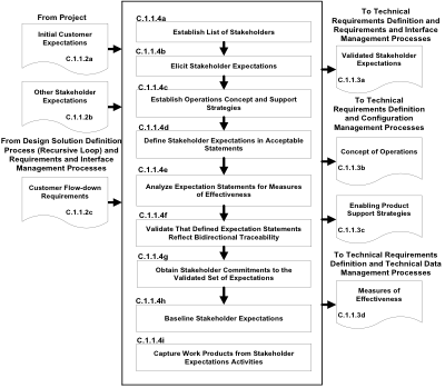
Figure C 1 - Stakeholder Expectation Definition Process
C.1.2 Technical Requirements Definition Process
C.1.2.1 Purpose
The technical requirements definition process is used to transform the baselined stakeholder expectations into unique, quantitative, and measurable technical requirements expressed as "shall" statements that can be used for defining a design solution definition for the end product and related enabling products of this layer.
C.1.2.2 Inputs and Sources:
a. Baselined set of stakeholder expectations, including interface requirements (from Stakeholder Expectations Definition and Configuration Management Processes).
b. Baselined Concept of Operation (from Stakeholder Expectations Definition and Configuration Management Processes).
c. Baselined Enabling Product Support Strategies (from Stakeholder Expectations Definition and Configuration Management Processes).
d. Measures of Effectiveness (from Stakeholder Expectations Definition and Technical Data Management Processes).
C.1.2.3 Outputs and Destinations:
a. Set of validated technical requirements that represents a reasonably complete description of the problem to be solved, including interface requirements (to Logical Decomposition and Requirements and Interface Management Processes).
b. Sets of MOPs that when met will satisfy the MOEs to which a set is related (to Logical Decomposition and Technical Data Management Processes).
c. A set of critical technical performance measures (TPMs) that if not met will put the project in cost, schedule, or performance risk status (to Technical Assessment Process).
Note: If process requirements were identified during this activity, they should be captured in distinct sections, volumes, or documents. These process requirements will not be verified as part of the product verification process but will be verified in other manners such as audits.
C.1.2.4 Activities
For the product layer in the system structure, the following activities are typically performed:
a. Analyze the scope of the technical problem to be solved to identify and resolve the design boundaries that identify: (1) which system functions are under design control and which are not; (2) expected interaction among system functions (data flows, human responses, and behaviors); (3) external physical and functional interfaces (mechanical, electrical, thermal, data, procedural) with other systems; (4) required capacities of system products; (5) timing of events, states, modes, and functions related to operational scenarios; and (6) emerging or maturing technologies necessary to make requirements.
b. Define constraints affecting the design of the system or products or how the system or products will be able to be used.
Note: Constraints that affect the design include cost, schedule, physical product constraints (e.g., color, texture, size, weight, buoyancy, use environment, rate of use, life-cycle services) and human constraints (e.g., operator physical and performance capabilities, operator work environment, and interfaces). Constraints are typically not able to be changed based on tradeoff analyses. Applicable industry standards should be referenced for possible constraints.
c. Define functional and behavioral expectations for the system or product in acceptable technical terms for the range of anticipated uses of system products as identified in the concept of operations. This permits separating defined stakeholder expectation functions and behaviors that belong to a lower level in the system structure and allocating them to the appropriate level.
d. Define the performance requirements associated with each defined functional and behavioral expectation.
Note: The performance requirements are expressed as the quantitative part of a requirement to indicate how well each product function is expected to be accomplished. Any qualitative performance expectations should be analyzed and quantified, and the performance requirements that can be changed by tradeoff analysis should be identified.
e. Define technical requirements in acceptable "shall" statements that are complete sentences with a single "shall" per numbered statement and have the following characteristics: (1) are individually clear, correct, and feasible; are not stated as to how it is to be satisfied; are implementable; have only one interpretation of meaning; have one actor-verb-object requirement; and can be validated at the level of the system structure at which they are stated; and (2) in pairs or as a set, have no redundancy, are consistent with terms used, are not in conflict with one another, and form a set of "design-to" requirements.
f. Validate that the resulting technical requirement statements: (1) have bidirectional traceability to the baselined stakeholder expectations; (2) were formed using valid assumptions; and (3) are essential to and consistent with designing and realizing the appropriate product solution form that will satisfy the applicable product life-cycle phase exit criteria.
g. Define MOPs for each identified MOE that cannot be directly used as a design-to technical requirement.
Note: Typically each qualitative MOE will have two or more MOPs made up of functional and performance requirement combinations. These quantitative MOPs, appropriately determined and defined, when designed in the design solution definition and met by a product generated by the product implementation process or product integration process, should help ensure that the qualitative MOEs (e.g., the seat is comfortable, no damage to the mission vehicle is caused by booster engine separation) will be satisfied.
h. Define appropriate TPMs by which technical progress will be assessed.
Note: TPMs are used for progress measurement and must meet certain criteria to be a valid TPM: (1) be a significant qualifier of the system (e.g., mass, power, weight, range, capacity, response time, safety parameter) that will be monitored at critical events (e.g., inspections, planned tests); (2) can be measured; and (3) projected progress profiles can be established (e.g., from historical data or based on test planning). TPMs provide an early warning method to flag potential technical problems in that the project will be put at technical performance, cost, or schedule risk if the requirement is not met. TPMs are typically selected from the MOPs.
i. Establish the technical requirements baseline.
Note: The baseline would be established and placed under change control by invoking the activities of the requirements management, interface management, and configuration management processes.
j. Capture the work products from technical requirements definition activities.
Note: The work products generated during the above activities should be captured along with key decisions made, supporting decision rationale and assumptions, and lessons learned in performing the technical requirements process activities to provide an understanding of the technical requirements baseline.
C.1.2.5 Process Flow Diagram
A typical process flow diagram for the technical requirements definition process is provided in Figure C-2 with inputs and their sources and the outputs and their destinations. The activities of the technical requirements definition process are truncated to indicate the action and object of the action.
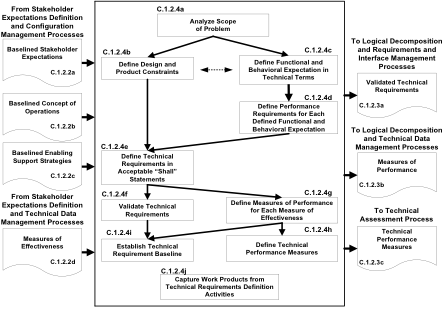
Figure C 2 - Technical Requirements Definition Process
C.1.3 Logical Decomposition Process
C.1.3.1 Purpose
The logical decomposition process is used to improve understanding of the defined technical requirements and the relationships among the requirements (e.g., functional, behavioral, performance, and temporal) and to transform the defined set of technical requirements into a set of logical decomposition models and their associated set of derived technical requirements for lower levels of the system and for input to the design solution definition process.
C.1.3.2 Inputs and Sources:
a. The baseline set of validated technical requirements, including interface requirements (from Technical Requirements Definition and Configuration Management Processes).
b. The defined MOPs (from Technical Requirements Definition and Technical Data Management Processes).
C.1.3.3 Outputs and Destinations:
a. Set of validated derived technical requirements, including interface requirements (to Design Solution Definition and Requirements and Interface Management Processes).
b. The set of logical decomposition models (to Design Solution Definition and Configuration Management Processes).
c. Logical decomposition work products (to Technical Data Management Processes).
C.1.3.4 Activities
For the product layer in the system structure, the following activities are typically performed:
a. Define one or more logical decomposition models based on the defined technical requirements to gain a more detailed understanding and definition of the design problem to be solved.
Note 1: The defined technical requirements can be decomposed and analyzed by functions, time, behaviors, data flow, objects, states and modes, and failure modes and effects, as pertinent to the program/project, to define sets of logical decomposition models. The models may include functional flow block diagrams, timelines, data control flow, states and modes, behavior diagrams, operator tasks, or functional failure modes and should be based on performance, cost, schedule, health and safety, and risk analyses.
Note 2: Use of existing products, which helps reduce development time and cost, may be considered in establishing logical decomposition models. New interfaces may appear with the introduction of existing products. These interfaces need to be included in the technical requirements, thus requiring an iteration of the technical requirements definition process.
Note 3: New technology insertion is considered at this point. The use of new technologies can provide a competitive edge but needs to be balanced against the risks of their insertion.
b. Allocate the technical requirements to the logical decomposition models to form a set of derived technical requirement statements that have the following characteristics:
Describe functional and performance, service and attribute, time, and data flow requirements, etc., as they pertain to the selected set of logical decomposition models.
Individually are complete sentences and are clear, correct, and feasible; not stated as to how to be satisfied; implementable; only have one interpretation of meaning, one actor-verb-object expectation; and can be validated at the level of the system structure at which it is stated.
In pairs or as a set, have an absence of redundancy, are adequately related with respect to terms used, and are not in conflict with one another.
Form a set of detailed "design-to" requirements.
Note: Traceability for the allocated MOPs should be maintained throughout the logical decomposition process. This is essential in that particular attention should be paid to demonstrating satisfaction of the MOPs during verification of a product generated by the product implementation process or product integration process.
c. Resolve derived technical requirement conflicts.
Note 1: The logical decomposition models and derived technical requirements should be analyzed to identify possible conflicts. The established set of performance criteria, cost, schedule, and risks should be used in conducting tradeoff analyses for conflict resolution.
Note 2: Conflicts among derived technical requirements are always a problem. This logical decomposition process activity is designed to discover such conflicts early and resolve them before the design solution definition is too far underway. Understanding the problem to be solved in more detail is helpful for obtaining a better and more cost-effective design solution definition.
d. Validate that the resulting set of derived technical requirements have: (1) bidirectional traceability with the set of validated technical requirements and (2) assumptions and decision rationales consistent with the source set of technical requirements.
Note 1: There may be some technical requirements that cannot be allocated to the logical decomposition models. If so, then these should be allocated directly to the physical entities that will make up the alternatives for design solution definition.
Note 2: Bidirectional requirements traceability is used for tracking changes to the technical requirements based on the logical decomposition models and their allocated derived technical requirements.
e. Establish the derived technical requirements baseline.
Note: The baselines would be established and placed under change control by invoking the activities of the requirements management, interface management, and configuration management processes.
f. Capture work products from logical decomposition activities.
Note: The work products generated during the definition of the derived technical requirements should be captured along with key decisions made, supporting decision rationale and assumptions, and lessons learned in performing the logical decomposition process activities to provide an understanding of the derived technical requirements baseline and the logical decomposition models and to permit traceability to technical requirements, stakeholder expectations, and logical decomposition models.
C.1.3.5 Process Flow Diagram
A typical process flow diagram for logical decomposition is provided in Figure C-3 with inputs and their sources and the outputs and their destinations. The activities of the logical decomposition process are truncated to indicate the action and object of the action.
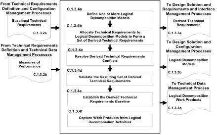
Figure C 3 - Logical Decomposition Process
C.1.4 Design Solution Definition Process
C.1.4.1 Purpose
The design solution definition process is used to translate the outputs of the logical decomposition process into a design solution definition that is in a form consistent with the product life-cycle phase and product layer location in the system structure and that will satisfy phase exit criteria. This includes transforming the defined logical decomposition models and their associated sets of derived technical requirements into alternative solutions, then analyzing each alternative to be able to select a preferred alternative and fully define that alternative into a final design solution that will satisfy the technical requirements. These design solution definitions will be used for generating end products either by using the product implementation process or product integration process as a function of the position of the product layer in the system structure and whether there are additional subsystems of the end product that need to be defined. The output definitions from the design solution (end product specifications) will be used for conducting product verification.
C.1.4.2 Inputs and Sources:
a. A baselined set of logical decomposition models (from Logical Decomposition and Configuration Management Processes).
b. A baseline set of derived technical requirements, including interface requirements (from Logical Decomposition and Configuration Management Processes).
Note: If there were unallocated technical requirements, these requirements would also be inputs to the design solution definition process.
C.1.4.3 Outputs and Destinations:
The specified requirements that describe the system design solution definition for the products of the product layer under development include:
a. A product layer design solution definition set of requirements for the system, including specification configuration documentation and external interface specification (to Requirements and Interface Management Process).
b. A baseline set of "make-to," "buy-to," "reuse-to," or set of "assemble and integrate-to" specified requirements (e.g., specifications, engineering drawings, computer-aided design (CAD) models, analytical models and configuration documents) for the desired end product of the product layer, including interface specifications (to Requirements and Interface Management Process).
Note: The specifications should include not only the product characteristics and functional and performance requirements, but also how each requirement will be evaluated during verification and/or acceptance tests.
c. The initial specifications for product layer subsystems for flow down to the next applicable lower level product layers, including interface specifications (to Stakeholder Expectations Definition, and Requirements and Interface Management Processes).
Note: If there is not a need for further development of end product subsystems, the product implementation process is the applicable destination of the end product specified requirements. (See C.1.4.2 above.)
d. The requirements for enabling products that will be needed to provide life-cycle support to the end products, including interface requirements (to Stakeholder Expectations Definition Process for development of enabling products or to Product Implementation Process for acquisition of existing enabling products, and Requirements and Interface Management Processes).
e. A product verification plan that will be used to demonstrate that the product generated from the design solution definition conforms to the design solution definition specified requirements (to Product Verification Process).
Note: The technical planning process should be used to develop this plan based on the product design solution definition process activities and the product verification process activities.
f. A product validation plan that will be used to demonstrate that the product generated from the design solution definition conforms to its set of stakeholder expectations (to Product Validation Process).
Note: The technical planning process should be used to develop this plan based on the product design solution definition process activities and the product validation process activities.
g. Baseline operate-to and logistics procedures (to Technical Data Management Process).
C.1.4.4 Activities
For the product layer in the system structure, the following activities are typically performed:
a. Define alternative solutions for the system end product being developed or improved that are consistent with the allocated and derived technical requirements.
Note 1: The derived technical requirements should be partitioned based on their associated logical decomposition model to potential physical elements that will make up the end product (e.g., hardware, software, human/manual operations, data, processes, and/or composites of these).
Note 2: Alternative solutions can be formed by packaging the physical elements in such a way that the derived technical requirements will be satisfied.
Note 3: Criteria should be established by which alternative solutions can be evaluated.
b. Analyze each alternative solution against defined criteria, such as satisfaction of external interface requirements; technology requirements; off-the-shelf availability of products; physical failure modes, effects, and criticality; life-cycle cost and support considerations; capacity to evolve; make vs. buy; standardization of products; integration concerns; and context of use issues of operators considering tasks, location, workplace equipment, and ambient conditions.
c. Select the best solution alternative based on the analysis results of each alternative solution and technical decision analysis recommendations.
Note: The decision analysis process is used to make an evaluated recommendation of the best or favored solution.
d. Generate the full design description of the selected alternative solution in a form appropriate to the product life-cycle phase, location of the product layer in the system structure, and phase exit criteria to include: (1) system specification and external interface specifications; (2) end product specifications, configuration description documents, and interface specifications; (3) end product subsystem initial specifications, if subsystems are required; (4) requirements for associated supporting enabling products; (5) end product verification plan; (6) end product validation plan; and (7) applicable logistics and operate-to procedures.
Note 1: The first application of the system design processes to develop a system structure typically results in a set of top-level requirements and one or more concepts. The form of design solution definition output could be, for example, a simulation model or paper study report.
Note 2: The output of the design solution definition process is typically called a technical data package. This package evolves from phase to phase starting with conceptual sketches or models and ending before fabrication, assembly and integration of the product with complete drawings, parts list, and other details needed for product implementation or product integration.
Note 3: Branches of the system structure tree end when there are no subsystems needed to make up an end product within a product layer. At that point the end product can be made, bought, or reused using the product implementation process. Any end product that consists of lower level subsystem products will be realized by the product integration process. The form of the product will be dependent on the product life-cycle phase, the location of the product layer in the system structure, and the phase exit criteria.
Note 4: The concept of operations for the end product should be updated to reflect the design solution definition selected ensuring that stakeholder expectations are still met.
e. Verify that the design solution definition: (1) is realizable within constraints imposed on the technical effort; (2) has specified requirements that are stated in acceptable statements and have bidirectional traceability with the derived technical requirements, technical requirements, and stakeholder expectations; and (3) has decisions and assumptions made in forming the solution consistent with its set of derived technical requirements, separately allocated technical requirements, and identified system product and service constraints.
Note 1: The use of peer reviews is recommended to evaluate the resulting design solution definition documentation against a set of established criteria consistent with the product life-cycle phase exit criteria and the product layer's location in the system structure.
Note 2: Identified anomalies should be resolved during the verification of the design solution definition.
f. Baseline the design solution definition specified requirements, including the specifications and configuration descriptions.
Note: The baselines would be established and placed under change and/or configuration control by invoking the activities of the requirements management, interface management, and configuration management processes.
g. Initiate development or acquisition of the life-cycle supporting enabling products needed for research, development, fabrication, integration, test, deployment, operations, sustainment, and disposal.
Note 1: Schedules should be such that the enabling products will be available when needed to support the product life-cycle phase activities.
Note 2: Development of enabling products and services relies on the same processes used to develop their associated operational products in the product layer.
h. Initiate development of the system products of the next lower level product layer, if any.
Note 1: Development of the next lower level of system products using the same design processes is an example of the recursive application of the repeatable system design processes.
Note 2: If this activity is not applicable, then the end product should be reviewed for making, buying, or reuse using the product implementation process.
i. Capture work products from the design solution definition activities.
Note: The work products generated during the above activities should be captured along with key decisions made, supporting decision rationale and assumptions, and lessons learned in performing the design solution definition process activities.
C.1.4.5 Process Flow Diagram
A typical process flow diagram for design solution definition is provided in Figure C-4 with inputs and their sources and the outputs and their destinations. The activities of the design solution definition process are truncated to indicate the action and object of the action.
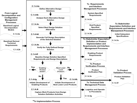
Figure C-4 - Design Solution Definition Process
There are five product realization processes. Four of the product realization processes are applied to each end product of a product layer from the bottom to the top of the system structure: (1) either product implementation or product integration, (2) product verification, (3) product validation, and (4) product transition. (See Figure 3-1 and Figure 3-2.) The form of the end product realized will depend on the applicable product life-cycle phase, location within the system structure of the product layer containing the end product, and the exit criteria of the phase. Typical early phase products are in the form of reports, models, simulations, mockups, prototypes, or demonstrators. Later phase product forms include the final mission products, including payloads and experiment equipment. The product realization process descriptions that follow assume that each lowest level product goes through the sequencing shown in Figure C-5. Exceptions will need to be planned according to what has and has not been already performed.
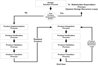
Figure C 5 - Sequencing of Product Realization Processes
C.2.1 Product Implementation Process
C.2.1.1 Purpose
The product implementation process is used to generate a specified product of a product layer through buying, making, or reusing in a form consistent with the product life-cycle phase exit criteria and that satisfies the design solution definition specified requirements (e.g., drawings, specifications).
C.2.1.2 Inputs and Sources:
a. Raw materials needed to make the end product (from existing resources or external sources).
b. End product design solution definition specified requirements (specifications) and configuration documentation for the end product of the applicable product layer, including interface specifications, in the form appropriate to satisfying the product life-cycle phase exit criteria (from Configuration Management Process).
c. Product implementation enabling products (from existing resources or Product Transition Process for enabling product realization).
C.2.1.3 Outputs and Destinations:
a. Made, bought, or reused end product in the form appropriate to the product life-cycle phase and to satisfy exit criteria (to Product Verification Process).
Note: For early life-cycle phases, products generated by the product implementation process can be in the form of reports, models, simulations, mockups, prototypes, and demonstrators. In later phases, the form may be mission-ready products, including payloads and experiment equipment.
b. Documentation and manuals in a form appropriate for satisfying the life-cycle phase exit criteria, including "as-built" product descriptions and "operate-to" and maintenance manuals (to Technical Data Management Process).
Note: "As-built" descriptions include materials for made, bought, or reused products. For early life-cycle phases, documents can be in draft form. In later phases, the documents/manuals should be in mission- or experiment-ready procedural form.
c. Product implementation work products needed to provide reports, records, and other outcomes of process activities (to Technical Data Management Process).
C.2.1.4 Activities
For the product layer in the system structure, the following activities are typically performed:
a. Prepare to conduct product implementation including: (1) prepare a product implementation strategy and detailed planning and procedures and (2) determine whether the product configuration documentation is adequately complete to conduct the type of product implementation as applicable for the product life-cycle phase, location of the product in the system structure, and phase exit criteria.
b. If the strategy is for buying an existing product, participate in the buy of the product including: (1) review the technical information made available by vendors to determine if the product meets the technical requirements; (2) assist the preparation of requests for acquiring the product from a vendor; (3) assist the inspection of the delivered product and the accompanying documentation; (4) determine whether the vendor conducted product validation or if it will need to be done by a project technical team; and (5) determine the availability of enabling products to provide test, operations, and maintenance support and disposal services for the product.
c. If the strategy is to reuse a product that exists in the Government inventory, participate in acquiring the reused product including: (1) review the technical information made available for the specified product to be reused to determine if the product meets the technical requirements; (2) determine supporting documentation and user manuals' availability; (3) determine the availability of enabling products to provide test, operations, and maintenance support and disposal services for the product; (4) assist the requests for acquiring the product from Government sources; and (5) assist the inspection of the delivered product and the accompanying documentation.
d. If the strategy is to make the product:
(1) Evaluate the readiness of the product implementation enabling products to make the product.
(2) Make the specified product in accordance with the specified requirements, configuration documentation, and applicable standards.
(3) Prepare appropriate product support documentation, such as integration constraints and/or special procedures for performing product verification and product validation.
e. Capture work products and related information generated while performing the product implementation process activities.
Note: Work products include procedures used, rationale for decisions made, assumptions made in product implementation, and decisions made, actions taken to correct identified anomalies, lessons learned in performing the product implementation activities, and updated product configuration and support documentation.
C.2.1.5 Process Flow Diagram
C.2.1.5.1 A typical process flow diagram for product implementation is provided in Figure C-6 with inputs and their sources and outputs and their destinations. The activities of the product implementation process are truncated to indicate the action and object of the action.
C.2.1.5.2 The path that products from the three sources in Figure C-6 take with respect to product verification, product validation, and product transition vary based on:
a. Whether the products bought have been verified and/or validated by the vendor.
b. Whether reuse products that come from within the organization have been verified and/or validated.
c. Whether the customer for the product desires to do the product validation or have the developer perform the product validation.
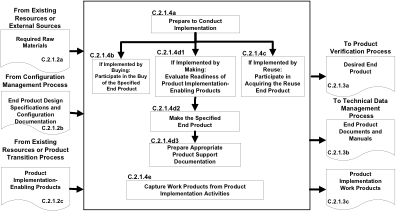
Figure C 6 - Product Implementation Process
C.2.2 Product Integration Process
C.2.2.1 Purpose
The product integration process is used to transform the design solution definition into the desired end product of the product layer through assembly and integration of lower level validated end products in a form consistent with the product life-cycle phase exit criteria and that satisfies the design solution definition requirements (e.g., drawings, specifications).
C.2.2.2 Inputs and Sources:
a. Lower level products to be assembled and integrated (from Product Transition Process).
b. End product design definition specified requirements (specifications) and configuration documentation for the applicable product layer, including interface specifications, in the form appropriate to satisfying the product life-cycle phase exit criteria (from Configuration Management Process).
c. Product integration enabling products (from existing resources or Product Transition Process for enabling product realization).
C.2.2.3 Outputs and Destinations:
a. Integrated product (s) in the form appropriate to the product life-cycle phase and to satisfy phase exit criteria (to Product Verification Process).
Note: For early life-cycle phases, products generated by the product integration process can be in the form of reports, models, simulations, mockups, prototypes, and demonstrators. In later phases, the form may be in mission-ready products, including payloads and experiment equipment.
b. Documentation and manuals in a form appropriate for satisfying the life-cycle phase exit criteria, including "as-integrated" product descriptions and "operate-to" and maintenance manuals (to Technical Data Management Process).
Note: "As-integrated" descriptions include descriptive materials for integrated products. For early life-cycle phases, documents can be in draft form. In later phases, the documents or manuals should be in mission- or experiment-ready procedural form.
c. Product integration work products needed to provide reports, records, and other outcomes of process activities (to Technical Data Management Process).
C.2.2.4 Activities
For the product layer in the system structure, the following activities are typically performed:
a. Prepare to conduct product integration to include: (1) preparing a product integration strategy, detailed planning for the integration, and integration sequences and procedures; and (2) determining whether the product configuration documentation is adequately complete to conduct the type of product integration applicable for the product life-cycle phase, location of the product in the system structure, and management phase exit criteria.
b. Obtain lower level products required to assemble and integrate into the desired product.
c. Confirm that the received products that are to be assembled and integrated have been validated to demonstrate that the individual products satisfy the agreed upon set of stakeholder expectations, including interfaces requirements. Note: Documented evidence that the correct products are provided for this activity is necessary. This validation can be completed by the providing organization or by an assigned technical team within the project.
d. Prepare the integration environment in which assembly and integration will take place to include evaluating the readiness of the product-integration enabling products and the assigned workforce.
Note: The product integration enabling products include, as a function of the product life-cycle phase, facilities, equipment, jigs, tooling, and assembly areas/lines. The integration environment includes test equipment, simulators (for products not available), storage areas, and recording devices.
e. Assemble and integrate the received products into the desired end product in accordance with the specified requirements, configuration documentation, interface requirements, applicable standards, and integration sequencing and procedures.
Note: This activity includes managing, evaluating, and controlling physical, functional, and data interfaces among the products being integrated.
f. Prepare appropriate product support documentation, such as special procedures for performing product verification and product validation.
g. Capture work products and related information generated while performing the product integration process activities.
Note: Work products include procedures used, rationale for decisions made, assumptions made in product integration, and decisions made, actions taken to correct identified anomalies, lessons learned in performing the product integration process activities, and updated product configuration and support documentation.
C.2.2.5 Process Flow Diagram
A typical process flow diagram for product integration is provided in Figure C-7 with inputs and their sources and the outputs and their destinations. The activities of the product integration process are truncated to indicate the action and object of the action.
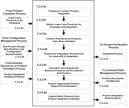
Figure C 7 - Product Integration Process
C.2.3 Product Verification Process
C.2.3.1 Purpose
The product verification process is used to demonstrate that an end product generated from product implementation or product integration conforms to its design solution definition requirements as a function of the product life-cycle phase and the location of the product layer end product in the system structure. Special attention is given to demonstrating satisfaction of the MOPs defined for each MOE during conduct of the technical requirements definition process.
Note: Product verification can be accomplished by inspections, analyses, demonstrations, or test in accordance with the verification plan and as a function of the product life-cycle phase.
C.2.3.2 Inputs and Sources:
a. End product to be verified (from Product Implementation Process or Product Integration Process).
b. End product specification and configuration baselines, including interface specifications, to which the product being verified was generated (from Technical Data Management Process).
Note: The baselines would be updated design solution definition specifications and configuration documents based on corrections made during product implementation or product integration.
c. Product verification plan (from Design Solution Definition Process and Technical Planning Process).
d. Product verification enabling products (from existing resources or Product Transition Process for enabling product realization).
C.2.3.3 Outputs and Destinations:
a. A verified end product (to Product Validation Process).
b. Product verification results (to Technical Assessment Process).
c. Completed verification report to include for each specified requirement: (1) the source paragraph references from the baseline documents for derived technical requirements, technical requirements, and stakeholder expectations; (2) bidirectional traceability among these sources; (3) verification type(s) to be used in performing verification of the specified requirement; (4) reference to any special equipment, conditions, or procedures for performing the verification; (5) results of verification conducted; (6) variations, anomalies, or out-of-compliance results; (7) corrective actions taken; and (8) results of corrective actions (to Technical Data Management Process).
Note: The information in this report is captured in what is often referred to as a verification matrix. This matrix is typically established and maintained once requirements traceability is initiated after obtaining stakeholder commitment to the set of stakeholder expectations.
d. Product verification work products needed to provide reports, records, and other outcomes of process activities (to Technical Data Management Process).
C.2.3.4 Activities
For the product layer in the system structure, the following activities are typically performed:
a. Prepare to conduct product verification to include as applicable to the product life-cycle phase and product layer location in the system structure: (1) reviewing the product verification plan for specific procedures, constraints, conditions under which verification will take place, pre- and post-verification actions, and criteria for determining the success or failure of verification methods and procedures; (2) arranging the needed product verification enabling products and support resources; (3) obtaining the end product to be verified; (4) obtaining the specification and configuration baseline against which the verification is to be made; and (5) establishing and checking the verification environment to ensure readiness for performing the verification.
b. Perform the product verification in accordance with the product verification plan and defined procedures to collect data on each specified requirement with specific attention given to MOPs.
c. Analyze the outcomes of the product verification, including identifying verification anomalies, establishing recommended corrective actions, and establishing conformance to each specified requirement under controlled conditions.
Note: Remedial and corrective actions should be assessed using the technical assessment process and decision analysis process with recommendations made and executed by planning the technical effort again, repeating the system design processes, and/or repeating the product verification.
d. Prepare a product verification report providing the evidence of product conformance with the applicable design solution definition specified requirements baseline to which the product was generated, including bidirectional requirements traceability and actions taken to correct anomalies of verification results.
Note: The recommended content of this report is provided in C.2.3.3.c.
e. Capture the work products from the product verification.
Note: Work products include verification outcomes; records of procedural steps taken against planned procedures; any failures or anomalies in the planned verification procedures, equipment, or environment; and records citing satisfaction or nonsatisfaction of verification criteria. Also records should document:
(1) the version of the set of specification and configuration documentation used;
(2) the version of the end product verified;
(3) the version or standard for tools and equipment used, together with applicable calibration data;
(4) results of each verification, including pass or fail declarations; and
(5) discrepancies between expected and actual results.
(6) Remedial and/or corrective action taken to resolve failures or anomalies to ensure end product conformance to the specified requirements.
(7) Waivers for any requirements that were not met.
C.2.3.5 Process Flow Diagram
A typical process flow diagram for product verification is provided in Figure C-8 with inputs and their sources and the outputs and their destinations. The activities of the product verification process are truncated to indicate the action and object of the action.
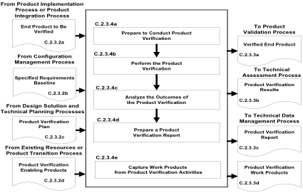
Figure C 8 - Product Verification Process
C.2.4 Product Validation Process
C.2.4.1 Purpose
The product validation process is used to confirm that a verified end product generated by product implementation or product integration fulfills (satisfies) its intended use when placed in its intended environment and to assure that any anomalies discovered during validation are appropriately resolved prior to delivery of the product (if validation is done by the supplier of the product) or prior to integration with other products into a higher level assembled product (if validation is done by the receiver of the product). The validation is done against the set of baselined stakeholder expectations. Special attention should be given to demonstrating satisfaction of the MOEs identified during conduct of the stakeholder expectations definition process. The type of product validation is a function of the form of the product, product life-cycle phase, and applicable customer agreement.
Note 1: A product should be validated against its stakeholders' expectations before being integrated into a higher level product.
Note 2: Product validation is conducted through demonstration, inspection, analysis test, or combination thereof.
C.2.4.2 Inputs and Sources:
a. End product to be validated (from Product Verification Process).
b. Baselined stakeholder expectations (from Configuration Management Process).
Note: The baselines would be updated based on corrections made during product implementation or product integration or as a result of correcting verification anomalies.
c. Product validation plan (from Design Solution Definition Process and Technical Planning Process).
d. Product validation enabling products (from existing resources or Product Transition Process for enabling product realization).
C.2.4.3 Outputs and Destinations:
a. A validated end product (to Transition Process).
b. Product validation results (to Technical Assessment Process).
c. Completed validation report for each stakeholder expectation or subset of stakeholder expectations involved with the validation, for example: (1) the source requirement paragraph reference from the stakeholder expectations baseline; (2) validation type(s) to be used in establishing compliance with selected set of stakeholder expectations and match with each source expectation referenced; (3) identification of any special equipment, conditions, or procedures for performing the validation, which includes referenced expectation; (4) results of validation conducted with respect to the referenced expectation; (5) deficiency findings (variations, anomalies, or out-of-compliance results); (6) corrective actions taken; and (7) results of corrective actions (to Technical Data Management Process).
Note: The information in this report is captured in what is often referred to as a validation cross-reference matrix. This matrix is typically established and maintained once requirements traceability is initiated after obtaining stakeholder commitment to the set of stakeholder expectations and establishing the stakeholder expectations baseline.
d. Product validation work products needed to provide reports, records, and other outcomes of process activities (to Technical Data Management Process).
C.2.4.4 Activities
For the product layer in the system structure, the following activities are typically performed:
a. Prepare to conduct product validation including, as applicable to the product life-cycle phase and product location in the system structure: (1) reviewing the product validation plan for specific procedures, constraints, conditions under which validation will take place, pre- and post-validation actions, and criteria for determining the success or failure of validation methods and procedures; (2) arranging the needed product validation enabling products and support resources; (3) obtaining the end product to be validated; (4) obtaining the stakeholder expectations baseline against which the validation is to be made; and (5) establishing and evaluating the validation environment to ensure readiness for performing the validation.
Note: Product validation environmental considerations include: measurement tools (scopes, electronic devices, probes); temporary embedded test software; recording equipment (capture test results); simulated subsystems in the loop (by software, electronics, or mechanics); simulated external interfacing products of other systems/products (representations of external threats or constraints); actual external interfacing products of other systems (aircraft, vehicles, boosters, humans); facilities; and skilled operators.
b. Perform the product validation in accordance with the product validation plan and defined procedures to collect data on performance of the product against stakeholder expectations with specific attention given to MOEs.
Note 1: Perform again any validation steps that were not in compliance with planned validation procedures or the planned environment, including equipment, measurement, or data capture failures.
Note 2: The validation environment may be a representative or simulated environment when it is not possible or cost prohibitive to use the operational environment.
c. Analyze the outcomes of the product validation to include identifying validation anomalies, establishing recommended remedial and corrective actions, and establishing conformance to stakeholder expectations under operational conditions (actual, analyzed, or simulated).
Note: Corrective actions should be assessed using the technical assessment process and decision analysis process with recommendations made and executed by planning the technical effort again and repeating the systems design processes and product realization processes.
d. Prepare a product validation report providing the evidence of product conformance with the stakeholder expectations baseline, including corrective actions taken to correct anomalies of validation results.
Note: The recommended content of this report is provided in C.2.4.3.c.
e. Capture the work products from the product validation.
Note: Work products include validation outcomes; records of procedural steps taken against planned procedures; any failures or anomalies in the planned validation procedures, equipment, or environment; and records citing satisfaction or nonsatisfaction of validation criteria. Also records should document:
(1) the version of the stakeholder expectations baseline used;
(2) the version of the end product validated;
(3) the version or standard for tools and equipment used, together with applicable calibration data;
(4) results of the product validation, including pass or fail declarations;
(5) discrepancies between expected and actual results; and
(6) waivers.
C.2.4.5 Process Flow Diagram
A typical process flow diagram for product validation is provided in Figure C-9 with inputs and their sources and the outputs and their destinations. The activities of the product validation process are truncated to indicate the action and object of the action.
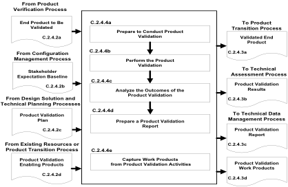
Figure C 9 - Product Validation Process
C.2.5 Product Transition Process
C.2.5.1 Purpose
The product transition process is used to transition to the customer at the next level in the system structure a verified and validated end product that has been generated by product implementation or product integration for integration into an end product. For the top level end product, the transition is to the intended end user. The form of the product transitioned will be a function of the product life-cycle phase exit criteria and the location within the system structure of the product layer in which the end product exists.
Note 1: Planning for transition includes preparation of packaging, handling, transporting, storing, training or certification activities and operations, users, or installation manuals for the product life-cycle phase and the location of the end product in the system structure.
Note 2: Depending on the agreement and the product life-cycle phase, the product transition process may include installation, training, and sustainment tasks.
Note 3: For transitions during early life-cycle phases, products may be in paper form, electronic form, physical models, or technology demonstration prototypes. During later life-cycle phases, products may be a one-of-a-kind operational/mission product or one of many to be produced and delivered in a single package or container.
C.2.5.2 Inputs and Sources:
a. End product or products to be transitioned (from Product Validation Process).
b. Documentation including manuals, procedures, and processes that are to accompany the end product (from Technical Data Management Process).
Note: In early product life-cycle phases, these manuals and documents would be in draft. In later phases, the manuals and documents should be in a form ready for use and should have been verified and/or validated that they meet end product and user support needs.
c. Product transition enabling products to include packaging materials, containers, handling equipment, and storage, receiving and shipping facilities (from existing resources or Product Transition Process for enabling product realization).
C.2.5.3 Outputs and Destinations:
a. Delivered end product with applicable documentation, including manuals, procedures, and processes in a form consistent with the product life-cycle phase and location of the product in the system structure (to end user or Product Integration Process�?�¢?"recursive loop).
Note 1: If a physical form of the product is delivered, the product should have been transitioned in protective packaging by appropriate handling and transporting mechanisms and/or stored in appropriate protective environments.
Note 2: If the end product is an enabling product providing life-cycle support (e.g., for product implementation, product integration, product verification, product validation, or product transition for the end product), the development or acquisition of the enabling product is needed to be initiated early so that it will be available when needed.
Note 3: The manuals and documents to be considered for delivery with the end product are the training modules, installation manuals, and operations and sustaining engineering processes to prepare users, installers, or maintainers to do their functions with respect to the transitioned product.
b. Product transition work products needed to provide reports, records, and other outcomes of process activities (to Technical Data Management Process).
c. Realized enabling products (to Product Implementation, Integration, Verification, Validation, and Transition Processes).
C.2.5.4 Activities
For the product layer in the system structure, the following activities are typically performed:
a. Prepare to conduct product transition to include: (1) preparing a product implementation strategy to establish the type of product transition to be made (to the next higher level customer for product integration or to an end user); and (2) reviewing related end product stakeholder expectations and design solution definition specified requirements to identify special transition procedures and enabling product needs for the type of product transition, if any, for packaging, storage, handling, shipping/transporting, site preparation, installation, or sustainment.
Note 1: The product life-cycle phase and the location of the end product in the system structure will influence the form of the end product and the packaging, storage, handling, and shipping/transporting required.
Note 2: The requirements for readying the product for transition are typically addressed in stakeholder expectations and end product design solution definition specified requirements. Included are packaging requirements for protection, security, and prevention of deterioration for products placed in storage or when it is necessary to transport or ship between and within organizational facilities or between organizations by land, air, and/or water vehicles. The end product requirements should state the spectrum of environmental and stress conditions specified for the package. Particular emphasis needs to be on protecting surfaces from physical damage and preventing corrosion, rodent damage to electronic wiring or cabling, shock or stress damage, heat warping or cold fractures, and moisture and other particulate intrusion that would damage moving parts. Other packaging considerations include: economy and ease of handling or transporting (e.g., containerization); accountability (e.g., tracking system in transit); and ease and safety of unpacking (e.g., shrink wrapping, sharp edges, strength of binding materials, environmental hazards of packing materials, and weight).
Note 3: The requirements for transporting the end product are typically addressed in enabling product requirements. Factors to consider include: safety to the product, property, and humans during moving; cost of transport options in terms of acquisition, installation, and maintenance; distances involved; environments through which the product will move; volume, space and weight restrictions on transport options; and handling to/from locations/transporters.
b. Evaluate the end product, personnel, and enabling product readiness for product transition including: (1) availability and appropriateness of the documentation that will be packaged and shipped with the end product; (2) adequacy of procedures for conducting product transition; (3) availability and skills of personnel to conduct product transition; and (4) availability of packaging materials/containers, handling equipment, storage facilities, and shipping/transporter services.
Note: Evaluations should include: (1) packaging, handling, shipping, and storage procedures; (2) installation procedures; (3) use instructions; and (4) other relevant documentation such as manuals and processes for developers, users, operators, trainers, installers, and support personnel.
c. Prepare the end product for transition to include the packaging and moving the product to the shipping/transporting location and any intermediate storage.
d. Prepare sites, as required, where the end product will be stored, assembled, integrated, installed, used, or maintained, as appropriate for the life-cycle phase, position of the end product in the system structure, and customer agreement.
Note: This may include making the end product ready for assembly and integration into an upper level product; bringing the product to operational/mission readiness (with appropriate acceptance and certification tests having been completed); placing the product into operation/use; training personnel such as users, operators, and maintainers; or providing in-service support (sustainment) of the end product for operations/use, monitoring, and maintenance.
e. Transition the end product with required documentation to the customer, based on the type of transition required, e.g., to the next higher level product layer for product integration or to the end user.
f. Capture work products from product transition process activities.
Note: Work products include procedures used, rationale for decisions made, assumptions made in product transition, and decisions made, actions taken to correct identified anomalies, lessons learned in performing the product transition process activities, and updated support documentation.
C.2.5.5 Process Flow Diagram
A typical process flow diagram for product transition is provided in Figure C-10 with inputs and their sources and the outputs and their destinations. The activities of the product transition process are truncated to indicate the action and object of the action.
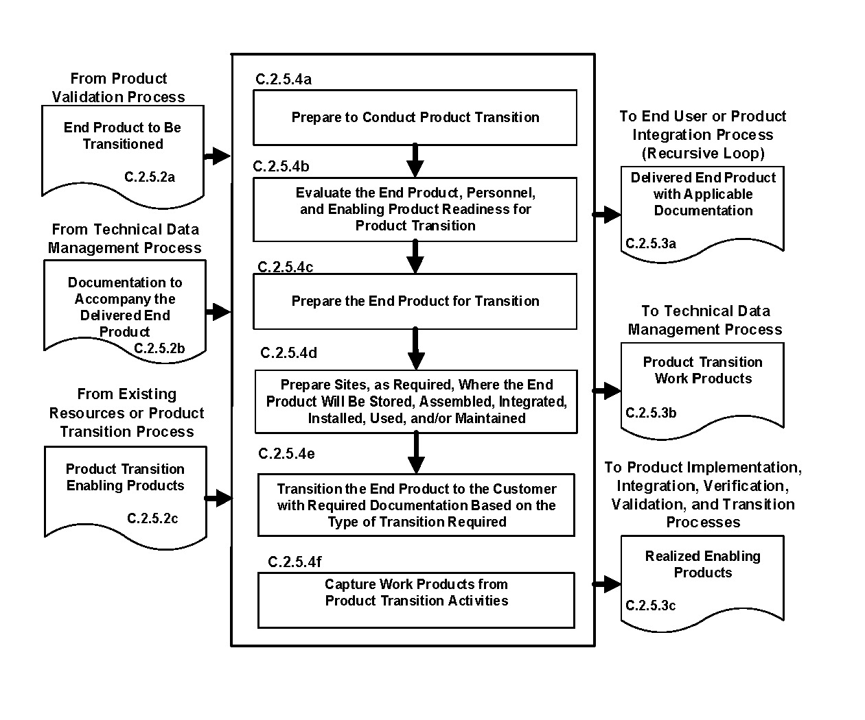
Figure C 10 - Product Transition Process
There are eight technical management processes; "Planning, Requirements Management, Interface Management, Risk Management, Configuration Management, Technical Data Management, Assessment, and Decision Analysis. (See Figure 3-1 and Figure 3-2.) These technical management processes are intended to supplement the management requirements defined in NPR 7120.5. The NPR provides program and project managers with the technical activities that they are required to be cognizant of and are responsible for. On the other hand, the technical management process in this SE NPR: (1) provides the technical team its requirements for planning, monitoring, and controlling the technical effort as well as the technical decision analysis requirements for performing tradeoff and effectiveness analyses to support decision making throughout the technical effort; (2) focuses on (a) completion of technical process planning (preparation of the SEMP and other technical plans), (b) technical progress assessment (using technical measures and conducting life-cycle and technical reviews to assess progress against the SEMP and defined technical requirements), and (c) control of product requirements, product interfaces, technical risks, configurations, and technical data; and (3) ensures that common technical process implementations comply with NPR 7150.2 software requirements for software aspects of the system. Documentation produced through each technical management process should be managed and disposed as Federal records.
C.3.1 Technical Planning Process
C.3.1.1 Purpose
The technical planning process is used to plan for the application and management of each common technical process. It is also used to identify, define, and plan the technical effort applicable to the product life-cycle phase for the product layer location within the system structure and to meet project objectives and product life-cycle phase exit criteria. A key document generated by this process is the SEMP. (See Chapter 6.)
Note: The results of this technical planning effort should be summarized and provided to the project manager as input to the technical summary section of the project plan required by NPR 7120.5.
C.3.1.2 Inputs and Sources:
a. Project technical effort requirements and project resource constraints (from the project).
b. Agreements, capability needs and applicable product life-cycle phase(s) (from the project).
c. Applicable policies, procedures, standards, and organizational processes (from the project).
d. Prior product life-cycle phase or baseline plans (from Technical Data Management Process).
e. Replanning needs (from Technical Assessment and Technical Risk Management Processes).
C.3.1.3 Outputs and Destinations:
a. Technical work cost estimates, schedules, and resource needs, e.g., funds, workforce, facilities, and equipment (to project).
b. Product and process measures needed to assess progress of the technical effort and the effectiveness of processes (to Technical Assessment Process).
c. The SEMP and other technical plans that support implementation of the technical effort (to all processes; applicable plans to Technical Processes).
d. Technical work directives, e.g., work packages or task orders with work authorization (to applicable technical teams).
e. Technical planning work products needed to provide reports, records, and other outcomes of process activities (to Technical Data Management Process).
C.3.1.4 Activities
For the product layer in the system structure, the following activities are typically performed:
a. Prepare to conduct technical planning to include:
(1) Preparing or updating a planning strategy for each of the common technical processes of this SE NPR. Determining:
(a) deliverable work products from technical efforts;
(b) technical reporting requirements;
(c) other technical information needs for reviews or satisfying product life-cycle management phase entry or exit criteria;
(d) product and process measures to be used in measuring technical performance, cost, and schedule progress;
(e) key or critical technical events with entry and success criteria;
(f) data management approach for data collection and storage and how measurement data will be analyzed, reported, and dispositioned as Federal records;
(g) technical risks that need to be addressed in the planning effort;
(h) tools and engineering methods to be employed in the technical effort; and
(i) approach to acquiring and maintaining the technical expertise needed (training and skills development plan).
b. Define the technical work to be done, including associated technical, support, and management tasks needed to generate the deliverable products and satisfy entry and success criteria of key technical events and the applicable product life-cycle management phase.
Note: Accurate identification of tasks is needed to help: (1) create viable schedules, (2) identify staffing needs, (3) determine resource loading, and (4) make acceptable cost estimations.
c. Schedule, organize, and determine the cost of the technical effort.
Note: Based on the defined technical work and identified critical events: (1) event-based and calendar-based schedules are prepared; (2) resource needs are established; (3) costs estimate are established; and (4) workforce, staff, and skill/training needs are identified and requested.
d. Prepare the SEMP and other technical plans needed to support the technical effort and perform the technical processes.
Note 1: The SEMP is described in Chapter 6, and an annotated outline is provided in Appendix D.
Note 2: Other technical plans include the product verification plan and product validation plan developed to support the product verification process and product validation process, respectively, and based on the design solution definition specified requirements to which the product to be evaluated will be generated.
Note 3: Larger projects can find descriptions of other technical plans that may be applicable to the project in ANSI/EIA 632. Smaller projects may include the provisions of applicable plans in the project plan. The key is to ensure that necessary technical activities and considerations are included in the technical effort.
e. Obtain stakeholder commitments to the technical plans.
Note: Review SEMP and other technical plans and reconcile them to reflect work and resource levels.
f. Issue authorized technical work directives to implement the technical work.
Note: Work packages or task orders that implement planned technical efforts are prepared and appropriate work authorizations requested. Authorized work directives are issued to technical teams assigned to perform the technical, support, and management activities of the planned technical effort.
g. Capture work products from technical planning activities.
Note: Work products include the planning strategy for developing any needed technical plans, procedures used for technical planning, rationale for decisions made, assumptions made during technical planning, and, with respect to decisions made, actions taken to correct identified anomalies, lessons learned in performing the technical planning activities, and updated support documentation.
C.3.1.5 Process Flow Diagram
A typical process flow diagram for technical planning is provided in Figure C-11 with inputs and their sources and the outputs and their destinations. The activities of the technical planning process are truncated to indicate the action and object of the action.
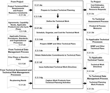
Figure C 11 - Technical Planning Process
C.3.2 Requirements Management Process
C.3.2.1 Purpose
The requirements management process is used to:
a. manage the product requirements identified, baselined, and used in the definition of the products of this layer during system design;
b. provide bidirectional traceability back to the top product layer requirements; and
c. manage the changes to established requirement baselines over the life cycle of the system products.
C.3.2.2 Inputs and Sources:
a. Stakeholder expectations and technical requirements to be managed (from System Design Processes).
b. Requirement change requests (from the project and Technical Assessment Process).
c. TPM estimation/evaluation results (from Technical Assessment Process).
d. Product verification and product validation results (from Product Verification and Validation Processes).
C.3.2.3 Outputs and Destinations:
a. Requirement documents (to Configuration Management Process).
b. Approved changes to requirement baselines (to Configuration Management Process).
c. Requirements management work products needed to provide reports, records, and other outcomes of process activities (to Technical Data Management Process).
Note: Bidirectional traceability status would be included as one of the work products and used in product verification and product validation reports.
C.3.2.4 Activities
For the product layer in the system structure, the following activities are typically performed:
a. Prepare to conduct requirements management, to include:
(1) Preparing or updating a strategy and procedures for:
(a) establishing that expectation and requirement statements, singularly and as a whole, are prepared in accordance with established formats and rules;
(b) identifying expectations and requirements to be managed, expectation and requirement sources, and allocation and traceability of requirements and linking product expectations and requirements with costs, weight, and power allocations, as applicable; and
(c) formal initiation, assessment, review, approval, and disposition of engineering change proposals and changes to expectation and requirements baseline.
(2) Selecting or updating an appropriate requirements management tool.
(3) Training technical team members in the established requirements management procedures and in the use of the selected/updated requirements management tool.
b. Conduct requirements management, to include: (1) capturing, storing, and documenting the expectations and requirements; (2) establishing that expectation and requirement statements are compliant with format and other established rules; (3) confirming that each established requirements baseline has been validated; and (4) identifying and analyzing out-of-tolerance system-critical technical parameters and unacceptable validation and verification results and proposing requirement-appropriate changes to correct out-of-tolerance requirements.
c. Conduct expectation and requirements traceability to include: (1) tracking expectations and requirements between baselines, especially MOEs, MOPs, and TPMs; and (2) establishing and maintaining appropriate requirements compliance matrixes that contain the requirements, bidirectional traceability, compliance status, and any actions to complete compliance.
d. Manage expectation and requirement changes to include: (1) reviewing engineering change proposals (ECPs) to determine any changes to established requirement baselines; (2) implementing formal change procedures for proposed and identified expectation or requirement changes; and (3) disseminating the approved change information.
e. Capture work products from requirements management process activities to include maintaining and reporting information on the rationale for and disposition and implementation of change actions, current requirement compliance status, and expectation and requirement baselines.
C.3.2.5 Process Flow Diagram
A typical process flow diagram for requirements management is provided in Figure C-12 with inputs and their sources and the outputs and their destinations. The activities of the requirements management process are truncated to indicate the action and object of the action.
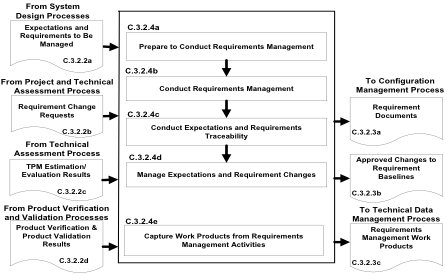
Figure C-12 - Requirements Management Process
C.3.3 Interface Management Process
C.3.3.1 Purpose
The interface management process is used to:
a. Establish and use formal interface management to assist in controlling system product development efforts when the efforts are divided between Government programs, contractors, and/or geographically diverse technical teams within the same program or project.
b. Maintain interface definition and compliance among the end products and enabling products that compose the system as well as with other systems with which the end products and enabling products must interoperate.
Note: A less formal interface management approach can be used in conjunction with requirements management and/or configuration management process activities when the technical effort is co-located in the same project.
C.3.3.2 Inputs and Sources:
a. Internal and external functional and physical interface requirements for the products of a product layer (from user or program and System Design Processes).
b. Interface change requests (from project and Technical Assessment Processes).
C.3.3.3 Outputs and Destinations:
a. Interface control documents (to Configuration Management Processes).
b. Approved interface requirement changes (to Configuration Management Process).
c. Interface management work products needed to provide reports, records, and other outcomes of process activities (to Technical Data Management Process).
C.3.3.4 Activities
For the product layer in the system structure, the following activities are typically performed:
a. Prepare or update interface management procedures for: (1) establishing interface management responsibilities for those interfaces that are part of agreement boundaries; (2) maintaining and controlling identified internal and external physical and functional interfaces; (3) preparing and maintaining appropriate physical and functional interface specifications or interface control documents and drawings to describe and control interfaces external to the system end product; (4) identifying interfaces between system products (including humans) and among configuration management items; (5) establishing and implementing formal change procedures for interface evolution; (6) disseminating the needed interface information for integration into technical effort activities and for external interface control; and (7) training technical teams and other applicable support and management personnel in the established interface management procedures.
Note: During application of the system design processes several kinds of interface requirements are baselined and thus need to be managed for each product layer:
(1) System (External). This external interface specifies the vertical functional, physical, electromagnetic, and human and interoperability requirements and characteristics in a system-to-system environment, e.g., end products with parent platform and external end products.
(2) End Product (Internal). This interface specification has horizontal internal interfaces with other end products and with the enabling products of the product layer.
(3) Enabling Product (Internal and External). This interface specification encompasses the horizontal interfaces with other enabling products and the end products of the same product layer and possibly vertical interfaces to other system end products and enabling products.
(4) Subsystem (Internal). This interface specification details the horizontal internal interfaces with the subsystem end products of the same parent within the product layer to ensure effective product integration with respect to form and fit, and, when the subsystem products are not physically mated together except by cabling or electronics, with respect to function.
b. Conduct interface management during system design activities for each product layer in the system structure to include: (1) integrating the interface management activities with requirements management activities; (2) analyzing the concept of operations to identify critical interfaces not included in the stakeholder set of expectations; (3) documenting interfaces both external and internal to each Product layer as the development of the system structure emerges and interfaces are added and existing interfaces are changed; (4) documenting origin, destination, stimulus, and special characteristics of interfaces; (5) maintaining the design solution definition for internal horizontal and vertical interfaces between Product layers in the system structure; (6) maintaining horizontal traceability of interface requirements across interfaces and capturing status in the established requirements compliance matrix; and (7) confirming that each interface control document or drawing that is established has been validated with parties on both sides of the interface.
c. Conduct interface management during product integration activities to include: (1) reviewing product integration procedures to ensure that interfaces are marked for easy and correct assembly/connection with other products; (2) identifying product integration planning to identify interface discrepancies, if any, and report to the proper technical team or technical manager; (3) confirming that a pre-check is completed on all physical interfaces before connecting products; (4) evaluating assembled products for interface compatibility; (5) confirming that product verification and product validation plans/procedures include confirming internal and external interfaces; and (6) preparing an interface evaluation report upon completion of integration, product verification, and product validation.
d. Conduct interface control to include: (1) managing interface changes within the system structure; (2) identifying and tracking proposed and directed changes to interface specifications and interface control documents and drawings; (3) confirming that the vertical and horizontal interface issues are analyzed and resolved when a change affects products on both sides of the interface; (4) controlling traceability of interface changes including source of the change, processing methods, and approvals; and (5) disseminating the approved interface change information for integration into technical efforts at every level of the project.
Note 1: Typically, an interface control working group (ICWG) establishes communication links between those responsible for design of interfacing systems, end products, enabling products, and subsystems. The ICWG has the responsibility to ensure accomplishment of the planning, scheduling, and execution of all interface activities. ICWGs are typically a technical team with appropriate technical membership from the project, each contractor, significant vendor, and program.
Note 2: An interface control document or drawing (ICD) is a document that establishes and defines the detailed interface between two or more systems, end products, system elements, or configuration items. It is used to control the defined interface early in the product life cycle and thus to reduce design changes due to poorly identified, managed, or controlled interfaces. Formal ICDs are typically necessary at external interfaces. Interfaces within the program/project may also be necessary and controlled either formally or informally to enable efficient design flexibility while still levying necessary internal interface requirements.
e. Capture work products from interface management activities. Note: Work products include the strategy and procedures for conducting interface management, rationale for interface decisions made, assumptions made in approving or denying an interface change, actions taken to correct identified interface anomalies, lessons learned in performing the interface management activities, and updated support and interface agreement documentation.
C.3.3.5 Process Flow Diagram
A typical process flow diagram for interface management is provided in Figure C-13 with inputs and their sources and the outputs and their destinations. The activities of the interface management process are truncated to indicate the action and object of the action.
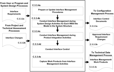
Figure C-13 - Interface Management Process
C.3.4 Technical Risk Management Process
C.3.4.1 Purpose
The technical risk management process is used to examine on a continuing basis the risks of technical deviations from program/project plans and to identify potential problems before they occur. Risk management is performed across the life of the program.
C3.4.2 Inputs and Sources
a. Program/Project Risk Management Plan (from program/project).
b. Technical risks (from program/project and other common technical processes).
c. Technical risk status measurements (from Technical Assessment and Decision Analysis Processes).
d. Technical risk reporting requirements (from program/project and Technical Planning Process).
C.3.4.3 Outputs and Destinations:
a. Technical risk mitigation and/or contingency actions (to Technical Planning Process for replanning and/or redirection).
b. Technical risk reports (to project and Technical Data Management Process).
c. Work products from technical risk management activities (to Technical Data Management Process).
C.3.4.4 Activities
For the product layer in the system structure, the following activities are typically performed: (NPR 8000.4, Agency Risk Management Procedural Requirements, is to be used as a source document for defining this process and implementing procedures. Additionally, NASA/SP-2011-3422, NASA Risk Management Handbook provides guidance for managing risk in an integrated fashion.)
a. Prepare a strategy to conduct technical risk management to include: (1) documenting how the program/project risk management plan will be implemented in the technical effort; (2) planning identification of technical risk sources and categories; (3) analyzing technical risks for likelihood and consequence; (4) characterizing and prioritizing technical risks; (5) planning informed technical management (mitigation) actions; (6) tracking technical risk status against established triggers; (7) resolving technical risk by taking planned action if established triggers are tripped; and (8) communicating technical risk status and mitigation actions taken, when appropriate.
b. Identify technical risks to include: (1) identifying sources of risks related to the technical effort; (2) anticipate what could go wrong in each of the source areas to create technical risks; (3) analyzing identified technical risks for cause and importance; (4) preparing clear, understandable, and standard form risk statements; and (5) coordinating with relevant stakeholders associated with each identified technical risk.
Note 1: Typical technical risk areas include: poorly defined technical tasks, cost estimations, calendar-driven scheduling, poor definition of requirements and interfaces, new technology, environmental conditions, planning assumptions, procedures used in performing technical processes, resource availability, workforce, budget, facilities, materials, and industrial base/supply chain.
Note 2: Technical risks are typically defined by relative time frame of risk occurrence, concerns or doubts about risk circumstances, limits or boundary of risk applicability, and potential consequences.
c. Conduct technical risk assessment to include: (1) categorize the severity of consequences for each identified technical risk in terms of performance, cost, schedule, and health and safety impacts to the technical effort and project; (2) analyze the likelihood and uncertainties of events associated with each technical risk either quantitatively (by determining the probabilities) or qualitatively (e.g., very high, high, moderate, low, or very low) the probability of occurrence in accordance with program/project risk management plan rules; and (3) prioritize risks for mitigation.
Note: Typically the prioritization of the technical risk is based on whether the risk is a near- or far-term concern; possible risk mitigation options and how long the options are viable; the coupling between various sources and characteristics of risk (e.g., technologies, requirements, interfaces, test approaches, manufacturing capacity, human error, logistics, workforce capability, schedules, and costs); how the occurrence of risk can be detected; and influences of other factors (e.g., quality, health and safety, security, and interoperability).
d. Prepare for technical risk mitigation to include: (1) selecting risks for mitigation and monitoring; (2) selecting an appropriate risk-handling approach; (3) establishing the risk level or threshold when risk occurrence becomes unacceptable and triggers execution of a risk mitigation action plan, which determines whether (a) a decision or general awareness/visibility to the next higher management level is needed, (b) a request for additional required resources for effective mitigation is needed, (c) there is a potential for transfer of risk tracking and/or control functions, and (d) coordination/integration is needed with other organizations/stakeholders both inside and outside the office; (4) integrating risk mitigation activities and milestones into the integrated master schedule; (5) selecting contingency actions and triggers should risk mitigation not work to prevent a problem occurrence; (6) preparing risk mitigation and contingency action plans identifying responsibilities and authorities.
e. Monitor the status of each technical risk periodically to include: (1) tracking risk status to determine whether conditions or situations have changed so that risk monitoring is no longer needed or new risks have been discovered; (2) comparing risk status and risk thresholds; (3) reporting risk status to decision authorities when a threshold has been triggered and by an action plan implemented; (4) preparing technical risk status reports as required by the program/project risk management plan; (5) communicating risk status during life-cycle and technical reviews in the form specified by the program/project risk management plan.
f. Implement technical risk mitigation and contingency action plans when the applicable thresholds have been triggered to include: (1) monitoring the results of the action plan implemented; (2) modifying the action plan as appropriate to the results of the actions; (3) continuing actions until the residual risk and/or consequences impacts are acceptable or become a problem to be solved; (4) communicate to the project when risks are beyond the scope of the technical effort to control, will affect a product higher in the system structure, or represent a significant threat to the technical effort or project success; (5) preparing action plan effectiveness reports as required by the project risk management plan; and (6) communicating action plan effectiveness during life-cycle and technical reviews in the form specified by the program/project risk management plan.
g. Capture work products from technical risk management activities.
Note: Work products include the strategy and procedures for conducting technical risk management; rationale for technical risk management decisions made; assumptions made in prioritizing, handling, and reporting technical risks and action plan effectiveness; actions taken to correct action plan implementation anomalies; and lessons learned in performing the technical risk management activities.
C.3.4.5 Process Flow Diagram
A typical process flow diagram for technical risk management is provided in Figure C-14 with inputs and their sources and the outputs and their destinations. The activities of the technical risk management process are truncated to indicate the action and object of the action.
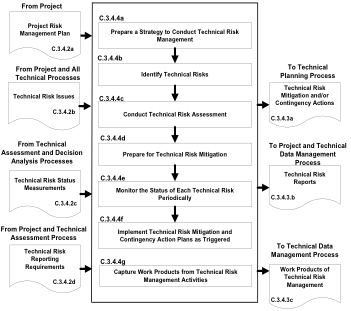
Figure C-14 - Technical Risk Management Process
C.3.5 Configuration Management Process
C.3.5.1 Purpose
The configuration management process for end products, enabling products, and other work products placed under configuration control is used to:
a. identify the configuration of the product or work product at various points in time;
b. systematically control changes to the configuration of the product or work product;
c. maintain the integrity and traceability of the configuration of the product or work product throughout its life; and
d. preserve the records of the product or end product configuration throughout its life cycle, disposing them in accordance with NPR 1441.1, NASA Records Retention Schedules.
C.3.5.2 Inputs and Sources:
a. Project configuration management plan, if any (from project).
b. Engineering Change Proposals (ECPs) from contractors, if any, and technical teams.
c. Expectations and requirement outputs to include stakeholder expectations, technical requirements, derived technical requirements, system and end product specifications, requirement documents, and interface control documents/drawings (from Requirements and Interface Management Processes).
d. Approved requirement baseline changes, including interface requirement changes (from Requirements Management and Interface Management Processes).
e. Concepts of operations, enabling product strategies, logical decomposition models, SEMP, technical plans, and other configuration items identified in the list of configuration items to be controlled (from Stakeholder Expectation Definition, Logical Decomposition, Technical Planning, and other technical processes).
f. Those identified risks with the potential to impact end products, enabling products, and other work products placed under configuration control.
C.3.5.3 Outputs and Destinations:
a. List of configuration items to be placed under control (to applicable technical processes).
b. Current baselines (to Technical Requirements Definition, Logical Decomposition, Design Solution Definition, and Product Implementation, Integration, Verification, and Validation Processes).
Note: A configuration management baseline identifies an agreed upon description of the attributes of a work product or set of work products at a point in time and provides a known configuration to which changes are addressed. Three example baselines for flight systems and ground support systems that are often referenced are the "functional," "allocated," and "product" baselines. Functional baselines are established for each product layer system element prior to the start of preliminary design. Allocated baselines are established for each Product layer end product with the successful completion of a Preliminary Design Review (PDR) at each level of the system structure. The product baseline represents the configuration of each end product.
c. Configuration management reports (to project and Technical Data Management Process).
d. Work products from configuration management activities (to Technical Data Management Process).
C.3.5.4 Activities
For the product layer in the system structure, the following activities are typically performed:
a. Prepare a strategy to conduct configuration management for the system products and designated work products to include: (1) documenting how the project configuration management plan, if any, will be implemented; (2) identifying items to be put under configuration control; (3) identifying schema of identifiers to accurately describe a configuration item and its revisions or versions; (4) controlling changes to configuration items; (5) maintaining and reporting disposition and implementation of change actions to appropriate stakeholders, including technical teams within the project; (6) ensuring that products are in compliance with specifications and configuration documentation during reviews and audits; (7) providing the appropriate reference configuration at the start of each product life-cycle phase; (8) obtaining appropriate tools for configuration management; and (9) training appropriate technical team members and other technical support and management personnel in the established configuration management strategy and any configuration management procedures and tools.
b. Identify baselines to be under configuration control to include: (1) listing the configuration items to control; (2) providing each configuration item with a unique identifier; (3) identifying acceptance requirements for each baseline identified for control; (4) identifying the owner of each configuration item; and (5) establishing a baseline configuration for each configuration item.
Note: Typical acceptance requirements for a baseline include: product life-cycle management phase and entry or exit criteria to be satisfied; when the baseline will be approved; when work products will be ready for evaluation; degree of control desired; cost and schedule limitations; and customer requirements.
c. Manage configuration change control to include: (1) establishing change criteria, procedures, and responsibilities; (2) receive, record, and evaluate change requests; (3) tracking change requests to closure; (4) obtaining appropriate approvals before implementing a change; (5) incorporating approved changes in appropriate configuration items; (6) releasing changed configuration items for use; and (7) monitoring implementation to determine whether changes resulted in unintended effects (e.g., have compromised safety or security of baseline product).
Note: A configuration management change board is typically established to receive, review, and approve change requests such as an engineering change proposal submitted by a contractor.
d. Maintain the status of configuration documentation to include: (1) maintaining configuration item description records and records that verify readiness of configuration items for testing, delivery, or other related technical efforts; (2) maintaining change requests, disposition action taken, and history of change status; (3) maintaining differences between successive baselines; and (4) controlling access to and release of configuration baselines.
e. Conduct configuration audits to include: (1) auditing baselines under control to confirm that the actual work product configuration matches the documented configuration, the configuration is in conformance with product requirements, and records of all change actions are complete and up to date; (2) identifying risks to the technical effort based on incorrect documentation, implementation, or tracking of changes; (3) assessing the integrity of the baselines; (4) confirming the completeness and correctness of the content of configuration items with applicable requirements; (5) confirming compliance of configuration items with applicable configuration management standards and procedures; and (6) tracking action items to correct anomalies from audit to closure.
f. Capture work products from configuration management activities to include a list of identified configuration items; description of configuration items placed under control; change requests, disposition of the requests, and rationale for the dispositions; documented changes with reason for changes and change actions; archive of old baselines; and required reports on configuration management outcomes.
C.3.5.5 Process Flow Diagram
A typical process flow diagram for configuration management is provided in Figure C-15 with inputs and their sources and the outputs and their destinations. The activities of the configuration management process are truncated to indicate the action and object of the action.
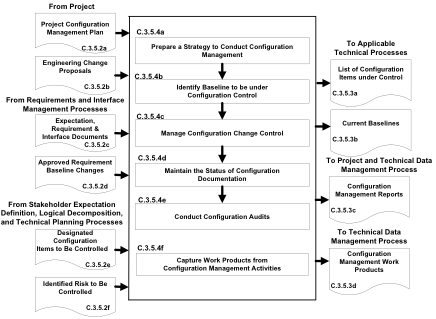
Figure C-15 - Configuration Management Process
C.3.6 Technical Data Management Process
C.3.6.1 Purpose
The technical data management process is used to:
a. provide the basis for identifying and controlling data requirements;
b. responsively and economically acquire, access, and distribute data needed to develop, manage, operate, and support system products over their product life;
c. manage and dispose data as records;
d. analyze data use;
e. if any of the technical effort is performed by an external contractor, obtain technical data feedback for managing the contracted technical effort; and
f. assess the collection of appropriate technical data and information.
g. effectively manage authoritative data that defines, describes, analyzes, and characterizes a product life cycle.
h. ensure consistent, repeatable use of effective PDLM processes, best practices, interoperability approaches, methodologies, and traceability.
i. Ensure product data accessibility and availability, including a method to archive the data.
C.3.6.2 Inputs and Sources:
a. Technical data and work products to be managed (from all technical processes and contractors).
b. Requests for technical data (from all technical processes and project).
C.3.6.3 Outputs and Destinations:
a. Form of technical data products (to all technical processes and contractors).
b. Technical data electronic exchange formats (to all technical processes and contractors).
c. Delivered technical data (to project and all technical processes).
C.3.6.4 Activities
For the product layer in the system structure, the following activities are typically performed:
a. Prepare a strategy for the conduct of technical data management to include: (1) determining required data content and form and electronic data exchange interfaces in accordance with international standards or agreements; (2) establishing a framework for technical data flow within the project technical processes and to/from contractors; (3) designating technical data management responsibilities and authorities regarding origination, generation, capture, archiving, security, privacy, and disposition of technical data work products; (4) establishing the rights, obligations, and commitments regarding the retention of, transmission of, and access to technical data items; (5) establishing relevant data storage, transformation, transmission, and presentation standards and conventions to be used; (6) establishing project or program policy and agreements or legislative constraints; (7) describing the methods, tools, and metrics used during the technical effort and for technical data management; and (8) training appropriate technical team members and support and management personnel in the established technical data management strategy and related procedures and tools.
b. Collect and store required technical data to include: (1) identifying existing sources of technical data that are designated as outputs of the common technical processes; (2) collecting and storing technical data in accordance with the technical data management strategy and procedures; (3) recording and distributing lessons learned; (4) performing technical data integrity checks on collected data to confirm compliance with content and format requirements and identifying errors in specifying or recording data; and (5) prioritizing, reviewing, and updating technical data collection and storage procedures.
c. Maintain stored technical data to include: (1) managing the databases to maintain proper quality and integrity of the collected and stored technical data and to confirm that the technical data is secure and is available to those with authority to have access; (2) performing technical data maintenance as required; (3) preventing the stored data from being used or accessed inappropriately; (4) maintaining the stored technical data in a manner that protects it against foreseeable hazards, such as fire, flood, earthquake, and riots; and (5) maintaining periodic backups of each technical database.
d. Provide technical data to authorized parties to include: (1) maintaining an information library or reference index to provide data available and access instructions; (2) receiving and evaluating requests for technical data and delivery instructions; (3) confirming that required and requested technical data is appropriately distributed to satisfy the needs of the requesting party and in accordance with established procedures, directives, and agreements; (4) confirming that electronic access rules are followed before allowing access to the database and before any data is electronically released/transferred to the requester; and (5) providing proof of correctness, reliability, and security of technical data provided to internal and external recipients.
e. Capture work products from technical data management activities.
Note: The work products generated during the above activities should be captured along with key decisions made, supporting decision rationale and assumptions, and lessons learned in performing the technical data management process.
C.3.6.5 Process Flow Diagram
A typical process flow diagram for technical data management is provided in Figure C-16 with inputs and their sources and the outputs and their destinations. The activities of the technical data management process are truncated to indicate the action and object of the action.
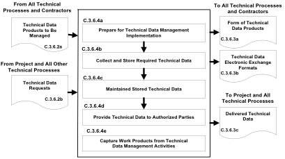
Figure C-16 - Technical Data Management Process
C.3.7 Technical Assessment Process
C.3.7.1 Purpose
The technical assessment process is used to help monitor progress of the technical effort and provide status information for support of the system design, product realization, and technical management processes.
C.3.7.2 Inputs and Sources:
a. Process and product measures (from Technical Planning Process).
b. Technical plans, including the SEMP (from Technical Planning Process).
c. Risk reporting requirements during life-cycle and technical reviews (from project).
d. Technical cost and schedule status reports (from project).
e. Product measurements (from Product Verification and Product Validation Processes).
f. Decision support recommendations and impacts (from Decision Analysis Process).
C.3.7.3 Outputs and Destinations:
a. Assessment results and findings, including technical performance measurement estimates of measures (to Technical Planning, Technical Risk Management, and Requirements Management Processes).
b. Analysis support requests (to Decision Analysis Process).
c. Life-cycle and technical review reports (to project and Technical Data Management Process).
d. Corrective action and requirement change recommendations, including actions to correct out-of-tolerance TPMs (to Technical Planning, Requirements Management, and Interface Management Processes).
e. Work products from technical assessment activities (to Technical Data Management Process).
C.3.7.4 Activities
For the product layer in the system structure, the following activities are typically performed:
a. Prepare a strategy for conducting technical assessments to include: (1) identifying the plans against which progress and achievement of the technical effort are to be assessed; (2) establishing procedures for obtaining cost expenditures against work planned and task completions against schedule; (3) identifying and obtaining technical requirements against which product development progress and achievement will be assessed and establishing the procedures for conducting the assessments; (4) establishing events when TPMs, estimation or measurement techniques, and rules for taking action when out-of-tolerance conditions exist will be assessed; (5) identifying and planning for phase-to-phase life-cycle and technical reviews and product layer vertical progress reviews, as well as establishing review entry and success criteria, review board members, and close-out procedures; (6) establishing which technical effort work products will undergo peer review, the team members who will perform the peer reviews, and reporting requirements; and (7) training team members, support staff, and managers involved in conducting technical assessment activities.
b. Assess technical work productivity (progress and achievement against plans) to include: (1) identifying, collecting, and analyzing process measures (e.g., earned value measurements for measuring progress against planned cost, schedule, resource use, and technical effort tasks) and identifying and reporting cost-effective changes to correct variances; (2) monitoring stakeholder involvement according to the SEMP; and (3) monitoring technical data management against plans.
c. Assess product quality (progress and achievements against technical requirements) to include: (1) identifying, collecting, and analyzing the degree of technical requirement and TPM satisfaction; (2) assessing the maturity of the product layer products and services as applicable to the product life-cycle phases; (3) determining any variances from expected values of product performance and identifying and defining cost-effective changes to correct variances.
Note: Product measures tell the degree of satisfaction of stakeholder expectations and deliver an ever improving value to the customers of system products and services. Product measures also indicate that the design process is continuing in the direction of an acceptable solution. An example of an input product measure is the quality of materials and skills of assigned project personnel. An example of an output metric is a TPM. A TPM provides an early warning of the adequacy of a design in satisfying selected critical technical parameter requirements. A "critical technical parameter" is one that characterizes a significant total system qualifier (e.g., one or more of the MOPs). TPMs also examine the marginal cost benefit of performance in excess of requirements. In addition, it should be possible to project the evolution of the parameter as a function of time toward the desired value at the completion of development. The projection can be based on test, planning, or historical data.
d. Conduct technical reviews to include: (1) identifying the type of life-cycle and technical reviews and each review's purpose and objectives (see Chapter 5 for specific life-cycle reviews that apply); (2) determining progress toward satisfying entry criteria; (3) establishing the makeup of the review team; (4) preparing the review presentation materials; and (5) identifying and resolving action items resulting from the review.
Note 1: Reviews are typically closed out when the minutes have been prepared, approved, and distributed; action items have been resolved; and the review completion documented and approved by the review chairperson.
Note 2: This activity includes peer reviews, which are planned, focused reviews by technical team peers on a single work product with the intent of identifying issues prior to that work product moving on to the next step. A peer review includes planning, preparing, conducting, analyzing outcomes, and identifying and implementing corrective actions.
e. Capture work products from the conduct of technical assessment activities to include: (1) identifying variances resulting from technical assessments; (2) identifying and reporting changes to correct variances; (3) recording methods used in doing assessment activities; (4) documenting assumptions made in arriving at the process and product measure outcomes; and (5) reporting corrective action recommendations.
C.3.7.5 Process Flow Diagram
A typical process flow diagram for technical assessment is provided in Figure C-17 with inputs and their sources and the outputs and their destinations. The activities of the technical assessment process are truncated to indicate the action and object of the action.
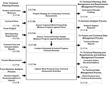
Figure C 17 - Technical Assessment Process
C.3.8 Decision Analysis Process
C.3.8.1 Purpose
The decision analysis process, including processes for identification of decision criteria, identification of alternatives, analysis of alternatives, and alternative selection, is applied to technical issues to support their resolution. It considers relevant data (e.g., engineering performance, quality, and reliability) and associated uncertainties. This process is used throughout the system life cycle to evaluate the impact of decisions on health and safety, technical, cost, and schedule performance. NASA/SP-2010-576, NASA Risk-informed Decision Making Handbook provides guidance for analyzing decision alternatives in a risk-informed fashion.
C.3.8.2 Inputs and Sources:
a. Decisions needed, alternatives, issues, or problems and supporting data (from all Technical Processes).
b. Analysis support requests (from Technical Assessment Process).
C.3.8.3 Outputs and Destinations:
a. Alternative selection recommendations and impacts (to all Technical Processes).
b. Decision support recommendations and impacts (to Technical Assessment Process).
c. Work products of decision analysis activities (to Technical Data Management Process).
C.3.8.4 Activities
For the product layer in the system structure, the following activities are typically performed:
a. Establish guidelines to determine which technical issues are subject to a formal analysis/evaluation process to include: (1) when to use a formal decision-making procedure, for example, as a result of an effectiveness assessment, a technical tradeoff, a problem needing to be solved, action needed as a response to risk exceeding the acceptable threshold, verification or validation failure, make/buy choice, evaluating a solution alternative, or resolving a requirements conflict; (2) what needs to be documented; (3) who will be the decision makers and their responsibilities and decision authorities; and (4) how decisions will be handled that do not require a formal evaluation procedure.
b. Define the criteria for evaluating alternative solutions to include: (1) the types of criteria to consider, including technology limitations, environmental impact, health and safety, risks, total ownership and life-cycle costs, and schedule impact; (2) the acceptable range and scale of the criteria; and (3) the rank of each criterion by its importance.
c. Identify alternative solutions to address decision issues to include alternatives for consideration in addition to those that may be provided with the issue.
d. Select evaluation methods and tools/techniques based on the purpose for analyzing a decision and on the availability of the information used to support the method and/or tool.
Note: Typical evaluation methods include: simulations; weighted trade-off matrices; engineering, manufacturing, cost, and technical opportunity studies; surveys; extrapolations based on field experience and prototypes; user analysis; and testing.
e. Evaluate alternative solutions with the established criteria and selected methods to include: (1) evaluation of assumptions related to evaluation criteria and of the evidence that supports the assumptions; and (2) evaluation of whether uncertainty in the values for alternative solutions affects the evaluation; (3) assessment of models and simulations, where applicable, to determine acceptability for the specific use and subsequent credibility of the produced results. The extent of these modeling and simulation assessments are to be determined by the criticality of the results, the risk of using incorrect results, and the degree to which the results influence a decision. Procedures for this are outlined in NASA STD-7009 and its associated Handbook (NASA-HDBK-7009).
f. Select recommended solutions from the alternatives based on the evaluation criteria to include documenting the information that justifies the recommendations and gives the impacts of taking the recommended course of action.
g. Report the analysis/evaluation results/findings with recommendations, impacts, and corrective actions.
h. Capture work products from decision analysis activities to include: (1) decision analysis guidelines generated and strategy and procedures used; (2) analysis/evaluation approach, criteria, and methods and tools used; (3) analysis/evaluation results, assumptions made in arriving at recommendations, uncertainties, and sensitivities of the recommended actions or corrective actions; and (4) lessons learned and recommendations for improving future decision analyses.
C.3.8.5 Process Flow Diagram
A typical process flow diagram for technical decision analyses is provided in Figure C-18 with inputs and their sources and the outputs and their destinations. The activities of the decision analysis process are truncated to indicate the action and object of the action.
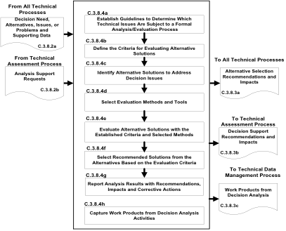
Figure C 18 - Decision Analysis Process
The purpose of this appendix is to provide an annotated outline for a SEMP for use by NASA programs and projects in planning the technical effort whether it is required for in-house or contracted projects. The SEMP outline provides guidance for the format and content of a project SEMP. The SEMP is the technical planning document for systems engineering. The SEMP is designed to be an integrated technical planning document for the conduct and management of the required technical effort. The resulting technical plan represents the agreed-to and approved tailoring of the requirements of the SE NPR to satisfy project technical requirements. The plan is used by the technical team responsible for generating technical work products to integrate and manage the full spectrum of technical activities required to engineer the system covered by the SEMP. The SEMP should be coordinated with the project plan for integration of the technical planning and modifications related to the allocated resources including cost, schedule, personnel, facilities, and deliverables required. The SEMP also will be used to evaluate the team's technical approach, to make technical risk assessments, and to measure progress.
Terminology is a key factor in ensuring a common understanding of the technical effort to be accomplished. Terms used in the SEMP should have the same meaning as the terms used in the SE NPR.
D.3.1 Outline Use
The SEMP outline in this appendix is guidance to be used in preparing a project SEMP. For a small project, the material in the SEMP can be placed in the project plan's technical summary and this annotated outline be used as a topic guide. D.3.2 Tailoring and Customization
Program and project tailoring and customization need to be consistent with Paragraph 2.2 of this NPR. The SEMP is to include documentation of any tailored requirements. Significant customization of SE processes should also be documented in the SEMP.
D.3.3 Surveillance-Type Projects
For projects with significant portions of the engineering work contracted out, the SEMP should scope and plan the NASA project's implementation of the common technical processes before, during, and at the completion of the contracted effort. This should include planning the technical team's involvement in RFP preparation, in source selection activities, and in acceptance of deliverables. The interface activities with the contractor, including NASA technical team involvement with and monitoring of contracted work, should be a focus of the SEMP.
D.4.1 SEMP Title Page
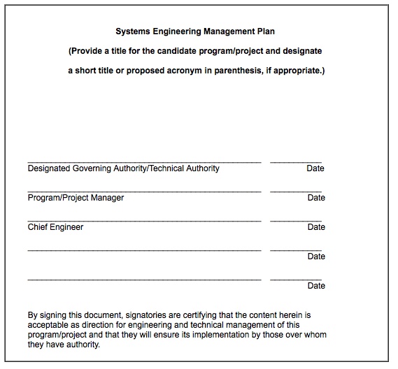
|
Figure D-1 - Systems Engineering Management Plan Title Page
D.4.2 General Structure
The SEMP contains the following sections, unless they have been tailored out. Cross references to detailed information in related technical plans are included in each pertinent SEMP section.
a. Purpose and Scope.
b. Applicable Documents.
c. Technical Summary.
d. Technical Effort Integration.
e. Common Technical Processes Implementation.
f. Technology Insertion.
g. Additional SE Functions and Activities.
h. Integration with the Project Plan and Technical Resource Allocation.
i. Compliance Matrix (Appendix H.2 of SE NPR).
j. Appendices.
D.4.3 Purpose and Scope
This section provides a brief description of the purpose, scope, and content of the SEMP. The scope encompasses the SE technical effort required to generate the work products necessary to meet the exit criteria for the product life-cycle phases.
D.4.4 Applicable Documents
This section lists the documents applicable to SEMP implementation and describes major standards and procedures that the technical effort needs to follow.
D.4.5 Technical Summary
This section contains an executive summary describing the problem to be solved by this technical effort.
D.4.5.1 System Description
This subsection contains a definition of the purpose of the system being developed and a brief description of the purpose of the products of the product layer of the system structure for which this SEMP applies. Each product layer includes the system end products and their subsystems and the supporting or enabling products and any other work products (plans, baselines) required for the development of the system. The description should include any interfacing systems and system products, including humans, with which the system products will interact physically, functionally, or electronically.
D.4.5.2 System Structure
This subsection contains an explanation of how the technical portion of the product layer (including enabling products, technical cost, and technical schedule) will be developed and integrated into the project piece of the work breakdown structure and how the overall system structure will be developed. This subsection contains a description of the relationship of the specification tree and the drawing tree with the products of the system structure and how the relationship and interfaces of the system end products and their life-cycle-enabling products will be managed throughout the planned technical effort.
D.4.5.3 Product Integration
This subsection contains an explanation of how the product will be integrated and will describe clear organizational responsibilities and interdependencies whether the organizations are geographically dispersed or managed across Centers. Project integration includes the integration of analytical products.
D.4.5.4 Planning Context
This subsection contains the programmatic constraints (e.g., NPR 7120.5) that affect the planning and implementation of the common technical processes to be applied in performing the technical effort. The constraints provide a linkage of the technical effort with the applicable product life-cycle phases covered by the SEMP including, as applicable, milestone decision gates, major life-cycle and technical reviews, key intermediate events leading to project completion, life-cycle phase, event entry and exit criteria, and major baseline and other work products to be delivered to the sponsor or customer of the technical effort.
D.4.5.5 Boundary of Technical Effort
This subsection contains a description of the boundary of the general problem to be solved by the technical effort, including technical and project constraints (governing NPR's use of heritage hardware, predefined interfaces, cost, schedule, and technologies) that affect the planning. Specifically, it identifies what can be controlled by the technical team (inside the boundary) and what influences the technical effort and is influenced by the technical effort but not controlled by the technical team (outside the boundary). Specific attention should be given to physical, functional, and electronic interfaces across the boundary.
D.4.5.6 Cross-References
This subsection contains cross-references to appropriate nontechnical plans that interface with the technical effort and contains a summary description of how the technical activities covered in other plans are accomplished as fully integrated parts of the technical effort.
D.4.6 Technical Effort Integration
This section contains a description of how the various inputs to the technical effort will be integrated into a coordinated effort that meets cost, schedule, and performance objectives.
D.4.6.1 Responsibility and Authority
This subsection contains a description of the organizing structure for the technical teams assigned to this technical effort and includes how the teams will be staffed and managed, including: (a) who will serve as the DGA for this project and, therefore, will have final approval for this SEMP; (b) how multidisciplinary teamwork will be achieved; (c) identification and definition of roles, responsibilities, and authorities required to perform the activities of each planned common technical process; (d) planned technical staffing by discipline and expertise level with human resource loading; (e) required technical staff training; and (f) assignment of roles, responsibilities, and authorities to appropriate project stakeholders or technical teams to ensure planned activities are accomplished.
D.4.6.2 Contractor Integration
This subsection contains a description of how the technical effort of in-house and external contractors is to be integrated with the NASA technical team efforts. This includes establishing technical agreements, monitoring contractor progress against the agreement, handling technical work or product requirements change requests, and acceptance of deliverables. The section will specifically address how interfaces between the NASA technical team and the contractor will be implemented for each of the 17 common technical processes. For example, it addresses how the NASA technical team will be involved with reviewing or controlling contractor-generated design solution definition documentation or how the technical team will be involved with product verification and product validation activities.
D.4.6.3 Analytical Tools That Support Integration
This subsection contains a description of the methods (such as integrated computer-aided tool sets, integrated work product databases, and technical management information systems) that will be used to support technical effort integration.
D.4.7 Common Technical Processes Implementation
Each of the 17 common technical processes will have a separate subsection that contains the plan for performing the required process activities as appropriately tailored. (See Paragraph 2.2 for the process activities required for tailoring.) Implementation of the 17 common technical processes includes: (1) generating outcomes needed to satisfy the entry and exit criteria of the applicable product life-cycle phase or phases identified in D.4.5.4; and (2) producing the necessary inputs for other technical processes. These sections contain a description of the approach, methods, and tools for:
a. Identifying and obtaining adequate human and nonhuman resources for performing the planned process, developing the work products, and providing the services of the process.
b. Assigning responsibility and authority for performing the planned process, developing the work products, and providing the services of the process.
c. Training the technical staff performing or supporting the process, where training is identified as needed.
d. Designating and placing designated work products of the process under appropriate levels of configuration management.
e. Identifying and involving stakeholders of the process throughout each phase of the life cycle.
f. Monitoring and controlling the process.
g. Objectively evaluating adherence of the process and the work products and services of the process to the applicable requirements, objectives, and standards and addressing noncompliance.
h. Reviewing activities, status, and results of the process with appropriate levels of management and resolving issues.
D.4.8 Technology Insertion
This section contains a description of the approach and methods for identifying key technologies and their associated risks and criteria for assessing and inserting technologies, including those for inserting critical technologies from technology development projects.
D.4.9 Additional SE Functions and Activities
This section contains a description of other areas not specifically included in previous sections but that are essential for proper planning and conduct of the overall technical effort.
D.4.9.1 System Safety
This subsection contains a description of the approach and methods for conducting safety analysis and assessing the hazards to operators, the system, the environment, and the public.
D.4.9.2 Engineering Methods and Tools
This subsection contains a description of the methods and tools not included in D.4.7 that are needed to support the overall technical effort and identifies those tools to be acquired and tool training requirements.
D.4.9.3 Specialty Engineering
This subsection contains a description of engineering discipline and specialty requirements that apply across projects and the product layer of the system structure. Examples of these requirement areas include planning for health and safety, reliability, human systems integration, logistics, maintainability, quality, operability, and supportability.
D.4.9.4 Technical Performance Measures
This subsection contains a description of the TPMs that have been derived from the MOEs and MOPs for the project. The set should include the required TPMs as stated in Paragraph 6.2.7 of this NPR, the appropriate set of highly recommended Common Leading Indicators as described in NPR 7120.5 Formulation Agreement and Program/Project Management Plan templates, and any other project-unique TPM selected for this project. The format and methodology of how the parameters will be reported (graph, table, plan versus actual, etc.) should be described. The reporting period and reporting recipients should also be stated.
D.4.9.5 Heritage
This section contains a description of the heritage or legacy products that will be used in the project. Discussions should include a list of the products and their use, the rationale for using them, if any delta certifications for the planned environments will be conducted, and any analysis performed to ensure their compatibility.
D.4.9.6 Other
This section is reserved for other SE functions and activities as needed.
D.4.10 Integration with the Project Plan and Technical Resource Allocation
This section contains how the technical effort will integrate with project management and defines roles and responsibilities. This section addresses how technical requirements will be integrated with the project plan to determinate the allocation of resources, including cost, schedule, and personnel, and how changes to the allocations will be coordinated.
D.4.11 Compliance Matrix
This section will include the completed compliance matrix per the template in Appendix H.2 of this NPR, including tailoring justifications.
D.4.12 Appendices
Appendices are included, as necessary, to provide a glossary, acronyms and abbreviations, and information published separately for convenience in document maintenance. Included would be: (a) information that may be pertinent to multiple topic areas (e.g., description of methods or procedures); (b) charts and proprietary data applicable to the technical efforts required in the SEMP; and (c) a summary of technical plans associated with the project. Each appendix should be referenced in one of the sections of the engineering plan where data would normally have been provided.
| TRL | Definition | Hardware Description | Software Description | Exit Criteria |
|---|---|---|---|---|
| 1 | Basic principles observed and reported | Scientific knowledge generated underpinning hardware technology concepts/applications. | Scientific knowledge generated underpinning basic properties of software architecture and mathematical formulation. | Peer reviewed publication of research underlying the proposed concept/application. |
| 2 | Technology concept and/or application formulated | Invention begins, practical applications is identified but is speculative, no experimental proof or detailed analysis is available to support the conjecture. | Practical application is identified but is speculative; no experimental proof or detailed analysis is available to support the conjecture. Basic properties of algorithms, representations, and concepts defined. Basic principles coded. Experiments performed with synthetic data. | Documented description of the application/concept that addresses feasibility and benefit. |
| 3 | -Analytical and experimental critical function and/or characteristic proof-of- concept | Analytical studies place the technology in an appropriate context and laboratory demonstrations, modeling and simulation validate analytical prediction. | Development of limited functionality to validate critical properties and predictions using non-integrated software components. | Documented analytical/experimental results validating predictions of key parameters. |
| 4 | Component and/or breadboard validation in laboratory environment. | A low fidelity system/component breadboard is built and operated to demonstrate basic functionality and critical test environments, and associated performance predictions are defined relative to final operating environment. | Key, functionality critical software components are integrated and functionally validated to establish interoperability and begin architecture development. Relevant environments defined and performance in the environment predicted. | Documented test performance demonstrating agreement with analytical predictions. Documented definition of relevant environment. |
| 5 | Component and/or breadboard validation in relevant environment. | A medium fidelity system/component brassboard is built and operated to demonstrate overall performance in a simulated operational environment with realistic support elements that demonstrate overall performance in critical areas. Performance predictions are made for subsequent development phases. | End-to-end software elements implemented and interfaced with existing systems/simulations conforming to target environment. End-to-end software system tested in relevant environment, meeting predicted performance. Operational environment performance predicted. Prototype implementations developed. | Documented test performance demonstrating agreement with analytical predictions. Documented definition of scaling requirements. |
| 6 | System/sub-system model or prototype demonstration in a relevant environment. | A high fidelity system/component prototype that adequately addresses all critical scaling issues is built and operated in a relevant environment to demonstrate operations under critical environmental conditions. | Prototype implementations of the software demonstrated on full-scale, realistic problems. Partially integrated with existing hardware/software systems. Limited documentation available. Engineering feasibility fully demonstrated. | Documented test performance demonstrating agreement with analytical predictions. |
| 7 | System prototype demonstration in an operational environment. | A high fidelity engineering unit that adequately addresses all critical scaling issues is built and operated in a relevant environment to demonstrate performance in the actual operational environment and platform (ground, airborne, or space). | Prototype software exists having all key functionality available for demonstration and test. Well integrated with operational hardware/software systems demonstrating operational feasibility. Most software bugs removed. Limited documentation available. | Documented test performance demonstrating agreement with analytical predictions. |
| 8 | Actual system completed and "flight qualified" through test and demonstration. | The final product in its final configuration is successfully demonstrated through test and analysis for its intended operational environment and platform (ground, airborne, or space). | All software has been thoroughly debugged and fully integrated with all operational hardware and software systems. All user documentation, training documentation, and maintenance documentation completed. All functionality successfully demonstrated in simulated operational scenarios. Verification and validation completed. | Documented test performance verifying analytical predictions. |
| 9 | Actual system flight proven through successful mission operations. | The final product is successfully operated in an actual mission. | All software has been thoroughly debugged and fully integrated with all operational hardware and software systems. All documentation has been completed. Sustaining software support is in place. System has been successfully operated in the operational environment. | Documented mission operational results. |
Note: In cases of conflict between NASA directives concerning TRL definitions, NPR 7123.1 will take precedence.
F.1 For non-configuration-controlled documents, the following terms and definitions are used in this document:
a. "Initial" is applied to products that are continually developed and updated as the program or project matures.
b. "Final" is applied to products that are expected to exist in this final form, e.g., minutes and final reports.
c. "Update" is applied to products that are expected to evolve as the formulation and implementation processes evolve. Only expected updates are indicated. However, any document may be updated as needed.
F.2 For configuration-controlled documents, the following terms and definitions are used in this document:
a. "Preliminary" is the documentation of information as it stabilizes but before it goes under configuration control. It is the initial development leading to a baseline. Some products will remain in a preliminary state for multiple reviews. The initial preliminary version is likely to be updated at a subsequent review but remains preliminary until baselined.
b. "Baseline" indicates putting the product under configuration control so that changes can be tracked, approved, and communicated to the team and any relevant stakeholders. The expectation on products labeled "baseline" is that they will be at least final drafts going into the designated review and baselined coming out of the review. Baselining a product does not necessarily imply that it is fully mature at that point in the life cycle. Updates to baselined documents require the same formal approval process as the original baseline.
c. "Approve" is used for a product, such as Concept Documentation, that is not expected to be put under classic configuration control but still requires that changes from the "Approved" version are documented at each subsequent "Update."
d. "Update" is applied to products that are expected to evolve as the formulation and implementation processes evolve. Only expected updates are indicated. However, any document may be updated as needed. Updates to baselined documents require the same formal approval process as the original baseline.
This appendix describes the recommended best practices for entrance and success criteria for the life-cycle and technical reviews required in Chapter 5 regardless of whether the review is accomplished in a one-step or two-step process. Terms for maturity levels of technical products defined in the tables of this appendix are addressed in detail in Appendix F. The products indicated in the entrance criteria cover the technical products for each review. Additional programmatic products may also be required by the appropriate governing project/program management NPR.
G.1 System Requirements Review (SRR) for Program
The SRR for a program is used to ensure that the program's functional and performance requirements are properly formulated and correlated with the Agency and Mission Directorate strategic objectives. Uncoupled, loosely coupled, tightly coupled and AO programs should use the entrance and success criteria in Table G-1. For projects and single-project programs, refer to Table G-4.
Table G-1 - SRR Entrance and Success Criteria for a Program
| System Requirements Review for a Program | |
|---|---|
| Entrance Criteria | Success Criteria |
|
1. Program requirements have been defined and support Mission Directorate strategic objectives. 2. The program requirements are adequately levied on either the single-program project or the multiple projects of the program.2 3. Traceability of program requirements to individual projects is documented in accordance with Agency needs, goals, and objectives, as described in the NASA Strategic Plan. 4. Definition of interfaces with other programs is complete and approved. 5. The program cost and schedule estimates are credible to meet program requirements. 6. Top risk identification is complete and mitigation strategies appear reasonable. 7. Evidence is provided that the program is compliant with NASA and implementing Center requirements, standards, processes, and procedures. 8. To-be-determined (TBD) and to-be-resolved (TBR) items are clearly identified with acceptable plans and schedules for their disposition. 9. The responsbile Center spectrum manager at the responsible Center was notified of preliminary requirements. |
* Product is required for programs/projects covered by NPR 7120.5. If there is disagreement between this table and NPR 7120.5, NPR 7120.5 takes precedence.
** Product is required per NPR 7123.1.
***Required per NPD 2570.5
G.2 System Definition Review for a Program
The SDR for a Program evaluates the credibility and responsiveness of the proposed program requirements/architecture to the Mission Directorate requirements, the allocation of program requirements to the projects, and the maturity of the program's mission/system definition. Uncoupled, loosely coupled, tightly coupled, and AO programs should use the entrance and success criteria in Table G-2. For project and single-project programs, refer to Table G-5.
Table G-2 - SDR Entrance and Success Criteria for a Program
| System Definition Review for a Program | |
|---|---|
| Entrance Criteria | Success Criteria |
|
|
* Product is required for programs/projects covered by NPR 7120.5. If there is disagreement between this table and NPR 7120.5, NPR 7120.5 takes precedence.
** Product is required per NPR 7123.1.
***Required per NPD 2570.5
G.3 Mission Concept Review
The MCR affirms the mission/project need and evaluates the proposed mission's objectives and the ability of the concept to fulfill those objectives.
Table G-3 - MCR Entrance and Success Criteria
| Mission Concept Review | |
|---|---|
| Entrance Criteria | Success Criteria |
|
|
* Product is required for programs/projects covered by NPR 7120.5. If there is disagreement between this table and NPR 7120.5, NPR 7120.5 takes precedence.
** Product is required per NPR 7123.1.
***Required per NPD 2570.5
G.4 System Requirements Review
The SRR evaluates whether the functional and performance requirements defined for the system are responsive to the program's requirements and ensures the preliminary project plan and requirements will satisfy the mission. This table is used for projects and single-project programs. For uncoupled, loosely coupled, tightly coupled, and AO programs, refer to Table G-1.
Table G-4 - SRR Entrance and Success Criteria
| System Requirements Review for Projects and Single-project Programs | |
|---|---|
| Entrance Criteria | Success Criteria |
|
|
* Product is required for programs/projects covered by NPR 7120.5. If there is disagreement between this table and NPR 7120.5, NPR 7120.5 takes precedence.
** Product is required per NPR 7123.1.
***Required per NPD 2570.5
G.5 Mission Definition Review/System Definition Review
The MDR/SDR evaluates whether the proposed mission/system architecture is responsive to the program mission/system functional and performance requirements and requirements have been allocated to all functional elements of the mission/system. This table is to be used for projects and single-project programs. For uncoupled, loosely coupled, tightly coupled, and AO programs, refer to Table G-2.
Table G-5 - MDR/SDR Entrance and Success Criteria
| Mission Definition Review/System Definition Review for Projects and Single-project Programs | |
|---|---|
| Entrance Criteria | Success Criteria |
|
|
* Product is required for programs/projects covered by NPR 7120.5. If there is disagreement between this table and NPR 7120.5, NPR 7120.5 takes precedence.
** Product is required per NPR 7123.1.
***Required per NPD 2570.5
G.6 Preliminary Design Review
The PDR demonstrates that the preliminary design meets all system requirements with acceptable risk and within the cost and schedule constraints and establishes the basis for proceeding with detailed design.
Table G-6 - PDR Entrance and Success Criteria
| Preliminary Design Review | |
|---|---|
| Entrance Criteria | Success Criteria |
|
|
* Product is required for programs/projects covered by NPR 7120.5. If there is disagreement between this table and NPR 7120.5, NPR 7120.5 takes precedence.
** Product is required per NPR 7123.1.
***Required per NPD 2570.5
G.7 Critical Design Review
The CDR demonstrates that the maturity of the design is appropriate to support proceeding with full-scale fabrication, assembly, integration, and test. CDR determines that the technical effort is on track to complete the system development, meeting performance requirements within the identified cost and schedule constraints.
Table G-7 - CDR Entrance and Success Criteria
| Critical Design Review | |
|---|---|
| Entrance Criteria | Success Criteria |
|
|
* Product is required for programs/projects covered by NPR 7120.5. If there is disagreement between this table and NPR 7120.5, NPR 7120.5 takes precedence.
** Product is required per NPR 7123.1.
***Required per NPD 2570.5
G.8 Production Readiness Review (PRR)
For projects developing or acquiring multiple or similar systems greater than three or as determined by the project. The PRR determines the readiness of the system developers to efficiently produce the required number of systems. It ensures that the production plans, fabrication, assembly, integration enabling products, operational support, and personnel are in place and ready to begin production.
Table G-8 - PRR Entrance and Success Criteria
| Production Readiness Review | |
|---|---|
| Entrance Criteria | Success Criteria |
|
|
*Required per NPD 2570.5
G.9 System Integration Review (SIR)
An SIR ensures segments, components, and subsystems are on schedule to be integrated into the system, and integration facilities, support personnel, and integration plans and procedures are on schedule to support integration.
Table G-9 - SIR Entrance and Success Criteria
| System Integration Review | |
|---|---|
| Entrance Criteria | Success Criteria |
|
|
* Product is required for programs/projects covered by NPR 7120.5. If there is disagreement between this table and NPR 7120.5, NPR 7120.5 takes precedence.
** Product is required per NPR 7123.1.
G.10 Test Readiness Review (TRR)
A TRR for each planned test or series of tests ensures that the test article (hardware/software), test facility, support personnel, and test procedures are ready for testing and data acquisition, reduction, and control.
Table G-10 - TRR Entrance and Success Criteria
| Test Readiness Review | |
|---|---|
| Entrance Criteria | Success Criteria |
|
|
*Required per NPD 2570.5
G.11 System Acceptance Review (SAR)
The SAR verifies the completeness of the specific end products in relation to their expected maturity level, assesses compliance to stakeholder expectations, and ensures that the system has sufficient technical maturity to authorize its shipment to the designated operational facility or launch site.
Table G-11 - SAR Entrance and Success Criteria
| System Acceptance Review | |
|---|---|
| Entrance Criteria | Success Criteria |
|
|
*Required per NPD 2570.5
G.12 Operational Readiness Review (ORR)
The ORR ensures that all system and support (flight and ground) hardware, software, personnel, procedures, and user documentation accurately reflect the deployed state of the system and are operationally ready.
Table G-12 - ORR Entrance and Success Criteria
| Operational Readiness Review | |
|---|---|
| Entrance Criteria | Success Criteria |
|
|
* Product is required for programs/projects covered by NPR 7120.5. If there is disagreement between this table and NPR 7120.5, NPR 7120.5 takes precedence.
** Product is required per NPR 7123.1.
***Required per NPD 2570.5
G.13 Flight Readiness Review (FRR)
The FRR examines tests, demonstrations, analyses, and audits that determine the system's readiness for a safe and successful flight or launch and for subsequent flight operations. The FRR also ensures that all flight and ground hardware, software, personnel, and procedures are operationally ready.
Table G-13 - FRR Entrance and Success Criteria
| Flight Readiness Review | |
|---|---|
| Entrance Criteria | Success Criteria |
|
|
* Product is required for programs/projects covered by NPR 7120.5. If there is disagreement between this table and NPR 7120.5, NPR 7120.5 takes precedence.
**Product is required NPR 7123.1
***Required per NPD 2570.5
G.14 Post-Launch Assessment Review (PLAR)
A PLAR evaluates the readiness of the spacecraft systems to proceed with full, routine operations after post-launch deployment. The review also evaluates the status of the project plans and the capability to conduct the mission with emphasis on near-term operations and mission-critical events.
Table G-14 - PLAR Entrance and Success Criteria
| Post-Launch Assessment Review | |
|---|---|
| Entrance Criteria | Success Criteria |
|
|
*Required per NPD 2570.5
G.15 Critical Event Readiness Review (CERR)
A CERR evaluates the readiness of the project and the flight system to execute the critical event during flight operation.
Table G-15 - CERR Entrance and Success Criteria
| Critical Event Readiness Review | |
|---|---|
| Entrance Criteria | Success Criteria |
|
|
*Required per NPD 2570.5
G.16 Post-Flight Assessment Review (PFAR)
The PFAR evaluates how well mission objectives were met during a mission and identifies all flight and ground system anomalies that occurred during the flight and determines the actions necessary to mitigate or resolve the anomalies for future flights of the same spacecraft design.
Table G-16 - PFAR Entrance and Success Criteria
| Post-Flight Assessment Review | |
|---|---|
| Entrance Criteria | Success Criteria |
|
|
G.17 Decommissioning Review (DR)
A DR confirms the decision to terminate or decommission the system and assesses the readiness of the system for the safe decommissioning and disposal of system assets.
Table G-17 - DR Entrance and Success Criteria
| Decommissioning Review | |
|---|---|
| Entrance Criteria | |
|
|
* Product is required for programs/projects covered by NPR 7120.5. If there is disagreement between this table and NPR 7120.5, NPR 7120.5 takes precedence.
** Product is required per NPR 7123.1.
G.18 Disposal Readiness Review (DRR)
A DRR confirms the readiness for the final disposal of the system assets.
Table G-18 - Disposal Readiness Review Entrance and Success Criteria
| Disposal Readiness Review | |
|---|---|
| Entrance Criteria | Success Criteria |
|
|
* Product is required for programs/projects covered by NPR 7120.5. If there is disagreement between this table and NPR 7120.5, NPR 7120.5 takes precedence
** Product is required per NPR 7123.1.
G.19 Peer Reviews
Peer reviews provide the technical insight essential to ensure product and process quality. Peer reviews are focused, in-depth technical reviews that support the evolving design and development of a product, including critical documentation or data packages. The participants in a peer review are the technical experts and key stakeholders for the scope of the review. Another purpose of the peer review is to add value and reduce risk through expert knowledge infusion, confirmation of approach, identification of defects, and specific suggestions for product improvements.
Table G-19 - Peer Review Entrance and Success Criteria
| Peer Review | |
|---|---|
| Entrance Criteria | Success Criteria |
|
|
G.20 Program Implementation Reviews (PIR) and Program Status Reviews (PSR)
PIRs or PSRs are periodically conducted, as required by the Decision Authority and documented in the program plan, during the Implementation phase to evaluate the program's continuing relevance to the Agency's Strategic Plan. These reviews assess the program performance with respect to expectations and determine the program's ability to execute the implementation plan with acceptable risk within cost and schedule constraints.
Table G-20 - PIR/PSR Entrance and Success Criteria
| Program Implementation and Program Status Reviews | |
|---|---|
| Entrance Criteria | Success Criteria |
|
|
* Required per NPD 2570.5
Template Instructions
This Compliance Matrix documents the Center's compliance with the requirements of this NPR or justification for tailoring of those requirements. While all requirements of this NPR are fundamentally owned by the OCE, in some cases responsibility for those requirements has been delegated to the Center Director. Since approval for tailoring of those delegated requirements is the responsibility of the Center Director (or delegate), only the undelegated OCE requirements are listed in this table. This compliance matrix will be filled out and submitted to the OCE upon request and attached to a copy of the Center procedures. The matrix lists:
The "Requirement Owner" column designates which organization is responsible for maintaining the requirement for the Agency and which therefore has the authority for tailoring unless this authority has been formally delegated.
The "Comply?" column is filled in to identify the Center's approach to the requirement. An "FC" is inserted for "fully compliant," "T" for "tailored," or "NA" for a requirement that is not applicable. The column titled "Justification" documents the rationale for tailoring, documents how the requirement will be tailored, or justifies why the requirement is not applicable.
| Req ID | SE NPR Paragraph | Requirement Statement | Rationale | Req. Owner | Comply? | Justification |
|---|---|---|---|---|---|---|
| SE-01 | 2.1.4.3.a | Center Directors shall perform the following activities: establish policies, procedures, and processes to execute the requirements of this SE NPR. | The requirements of this NPR are to be flowed into Center-level command media for execution. This may require not only Center-level requirements, but also policy statements, work instructions, or other supporting or enabling processes. It is the responsibility of the Center Directors or designees to ensure that this occurs. | OCE | ||
| SE-02 | 2.1.4.3.b | Center Directors shall perform the following activities: assess and take corrective actions to improve the execution of the requirements of this SE NPR. | Continual improvement of Agency and Center processes is necessary to ensure they are efficient and effective. It is the responsibility of the Centers to bring forward any recommendations for improvement of this NPR. | OCE | ||
| SE-03 | 2.1.4.3.c | Center Directors shall perform the following activities: select appropriate standards applicable to projects under their control. | It is the responsibility of the Center organizations to identify which Agency and/or Center technical standards should be applied to the programs and projects within their purview. These will be recommended to the programs/projects through the technical authority lines. | OCE | ||
| SE-04 | 2.1.4.3.d | Center Directors shall perform the following activities: Complete the compliance matrix, as tailored, in Appendix H.1 for those requirements owned by the Office of Chief Engineer, and provide to the OCE upon request. | The Centers are to fill out the compliance matrix in Appendix H.1 to indicate how the OCE-owned requirements of this NPR have been flowed into Center-level processes. This ensures that the OCE requirements of the Agency are flowed into the Centers and that any waiver/deviation from the Agency requirements has been identified and approved by the OCE. | OCE | ||
| SE-07 | 3.2.2.1 | Center Directors or designees shall establish and maintain a Stakeholder Expectations Definition process to include activities, requirements, guidelines, and documentation for the definition of stakeholder expectations for the applicable product layer. | This requirement ensures that the Centers identify how they will gather and address stakeholder expectations. This ensures that the project will gain a thorough understanding of what the customer and other stakeholders expect out of the programs/projects. | OCE | ||
| SE-08 | 3.2.3.1 | Center Directors or designees shall establish and maintain a Technical Requirements Definition process to include activities, requirements, guidelines, and documentation for the definition of technical requirements from the set of agreed upon stakeholder expectations for the applicable product layer. | This requirement ensures that the Centers identify how they will select and gain agreement on the technical requirements for the program/project. | OCE | ||
| SE-09 | 3.2.4.1 | Center Directors or designees shall establish and maintain a Logical Decomposition process to include activities, requirements, guidelines, and documentation for logical decomposition of the validated technical requirements of the applicable product layer. | This requirement ensures that the Centers identify how they will take the technical requirements for the program/project and glean from them what is needed to accomplish them (functional block diagrams, timing, architectures, etc.). This places the requirements into context and ensures they are understood well enough to begin the design process. | OCE | ||
| SE-10 | 3.2.5.1 | Center Directors or designees shall establish and maintain a Design Solution Definition process to include activities, requirements, guidelines, and documentation for designing product solution definitions within the applicable product layer that satisfy the derived technical requirements. | This requirement ensures that the Centers identify how they will take the information from the stakeholder expectations, requirements, and logical decomposition and perform the design function. Since all designs are unique, this will describe the general steps that are taken. The specifics for each of the program/projects will be documented in the SEMP. | OCE | ||
| SE-11 | 3.2.6.1 | Center Directors or designees shall establish and maintain a Product Implementation process to include activities, requirements, guidelines, and documentation for implementation of a design solution definition by making, buying, or reusing an end product of the applicable product layer. | This requirement ensures that the Centers identify how they will execute the designs, whether through buying items off the shelf or contracting to have them built, building/coding them within the Center, or reusing products already developed by another program/project. The specifics for how each program/project will make this determination for the various components/assemblies within the product hierarchy are documented in the SEMP. | OCE | ||
| SE-12 | 3.2.7.1 | Center Directors or designees shall establish and maintain a Product Integration process to include activities, requirements, guidelines, and documentation for the integration of lower level products into an end product of the applicable product layer in accordance with its design solution definition. | This requirement ensures that the Centers identify how they will approach the integration of products within successive levels of the product hierarchy. This ensures that planning is performed that will enable a smooth integration of products into higher level assemblies. | OCE | ||
| SE-13 | 3.2.8.1 | Center Directors or designees shall establish and maintain a Product Verification process to include activities, requirements/specifications, guidelines, and documentation for verification of end products generated by the product implementation process or product integration process against their design solution definitions. | This requirement ensures that the Centers identify how they will verify that the end products will comply with the technical requirements. | OCE | ||
| SE-14 | 3.2.9.1 | Center Directors or designees shall establish and maintain a Product Validation process to include activities, requirements, guidelines, and documentation for validation of end products generated by the product implementation process or product integration process against their stakeholder expectations. | This requirement ensures that the Centers identify how they will show that the end products will meet the stakeholder expectations in the intended environment. This is in addition to verifying they meet the stated requirements and ensures the stakeholder is getting what was expected. | OCE | ||
| SE-15 | 3.2.10.1 | Center Directors or designees shall establish and maintain a Product Transition process to include activities, requirements, guidelines, and documentation for transitioning end products to the next higher level product layer customer or user. | This requirement ensures that the Centers identify how they will handle the end products as they move from one location to another. This includes shipping, handling, transportation criteria, security needs, and receiving facility storage needs. It ensures that receiving facilities are ready to accept the product and that no damage occurs to the product during handling and transportation. | OCE | ||
| SE-16 | 3.2.11.1 | Center Directors or designees shall establish and maintain a Technical Planning process to include activities, requirements, guidelines, and documentation for planning the technical effort. | This requirement ensures that the Centers identify how they will perform and document all the technical planning for the program/project. This includes all plans developed for the technical effort ??"Systems Engineering Management Plans, risk plans, integration plans, and VandV plans. This ensures that the program/project teams are thinking ahead for the work to be performed and capturing that information so it can be communicated to the rest of the team, customers, and other stakeholders. | OCE | ||
| SE-17 | 3.2.12.1 | Center Directors or designees shall establish and maintain a Requirements Management process to include activities, requirements, guidelines, and documentation for management of requirements throughout the system life cycle. | This requirement ensures that the Centers identify how they will handle tracking and changes to the baselined set of requirements. It defines who has authority to submit and approve changes and how requirements are tracked as they flow down to other elements in the product breakdown structure. This ensures that changes to requirements are evaluated and that their impacts are understood and communicated to the rest of the team. | OCE | ||
| SE-18 | 3.2.13.1 | Center Directors or designees shall establish and maintain an Interface Management process to include activities, requirements, guidelines, and documentation for management of the interfaces defined and generated during the application of the system design processes. | This requirement ensures that the Centers identify how they will manage the internal and external interfaces of their end product. This will ensure compatibility when the various parts of the system are brought together for assembly/integration. | OCE | ||
| SE-19 | 3.2.14.1 | Center Directors or designees shall establish and maintain a Technical Risk Management process to include activities, requirements, guidelines, and documentation for management of the risk identified during the technical effort. | This requirement ensures that the Centers identify how they will handle the technical portions of the program/project risks and report them for inclusion with the programmatic risk portions. It ensures that the technical aspects of risks to the program/project's successful execution are captured and reported to program/project management who will be developing the overall risk posture. | OCE | ||
| SE-20 | 3.2.15.1 | Center Directors or designees shall establish and maintain a Configuration Management process to include activities, requirements, guidelines, and documentation for configuration management. | This requirement ensures that the Centers identify how they will perform configuration management of the end products, enabling products and other work products key to the program/project. The technical products to be controlled are identified and tracked to ensure that the team knows what the configuration of their system is at all phases of the life cycle. | OCE | ||
| SE-21 | 3.2.16.1 | Center Directors or designees shall establish and maintain a Technical Data Management process to include activities, requirements, guidelines, and documentation for management of the technical data generated and used in the technical effort. | This requirement ensures that the Centers identify how they will handle all the technical data that is generated by the program/project. This will include all data needed to manage, operate, and support the system products over the life cycle. It ensures that the data is available and secure when needed. | OCE | ||
| SE-22 | 3.2.17.1 | Center Directors or designees shall establish and maintain a Technical Assessment process to include activities, requirements, guidelines, and documentation for making assessments of the progress of planned technical effort and progress toward requirements satisfaction. | This requirement ensures that the Centers identify how they will assess the progress of the program/project's technical efforts, including life-cycle reviews. It ensures that the program/project team, customers, and other key stakeholders know how the effort is progressing and if additional actions are needed to resolve issues prior to becoming too costly. | OCE | ||
| SE-23 | 3.2.18.1 | Center Directors or designees shall establish and maintain a Decision Analysis process to include activities, requirements, guidelines, and documentation for making technical decisions. | This requirement ensures that the Centers identify how they will make and document key technical decisions. It helps to ensure that all team members know who can make decisions, what their authority levels are, and where to go to gain an understanding of what key decisions have been made. | OCE |
Template Instructions
The Compliance Matrix documents the program/project's compliance or intent to comply with the requirements of this NPR or justification for tailoring. It is attached to the SEMP when submitted for approval. The matrix lists:
Programs/Projects may substitute a matrix that documents their compliance with their particular Center's implementation of NPR 7123.1, if applicable.
The "Requirement Owner" column designates which organization is responsible for maintaining the requirement for the Agency and which, therefore, has the authority for tailoring unless this authority has been formally delegated.
The "Comply?" column is filled in to identify the program/project's approach to the requirement. An "FC" is inserted for "fully compliant," "T" for "tailored," or "NA" for a requirement that is "not applicable." The column titled "Justification" documents the rationale for tailoring, documents how the requirement will be tailored, or justifies why the requirement is not applicable.
| Req ID | SE NPR Paragraph | Requirement Statement | Rationale | Req. Owner | Comply? | Justification |
|---|---|---|---|---|---|---|
| SE-05 | 2.1.5.2 | For those requirements owned by Center Directors, the technical team shall complete the compliance matrix in Appendix H.2 and include it in the SEMP. | For programs and projects, the compliance matrix in Appendix H.2 is filled out showing that the program/project is compliant with the requirements of this NPR (or a particular Center's implementation of NPR 7123.1, whichever is applicable) or any tailoring thereof is identified and approved by the Center Director or designee as part of the program/project SEMP. | CD | ||
| SE-06 | 2.1.6.1 | The DGA shall approve the SEMP, waiver authorizations, and other key technical documents to ensure independent assessment of technical content. | The DGA, who is often the TA, provides an approval of the SEMPs, waivers to technical requirements and other key technical document to provide assurance of the applicability and technical quality of the products. | CD | ||
| SE-24 | 4.2.1 | The NASA technical team shall define the engineering activities for the periods before contract award, during contract performance, and upon contract completion in the SEMP. | It is important for both the Government and contractor technical teams to understand what activities will be handled by which organization throughout the product life cycle. The contractor(s) will typically develop a SEMP or its equivalent to describe the technical activities in their portion of the project, but an overarching SEMP is needed that will describe all technical activities across the life cycle whether contracted or not. | CD | ||
| SE-25 | 4.2.2 | The NASA technical team shall use common technical processes, as implemented by the Center's documentation, to establish the technical inputs to the RFP appropriate for the product to be developed, including product requirements and Statement of Work tasks. | The technical team's participation in the development of the RFP is critical to enabling a successful contracted effort. Ensuring that the proper application of the common technical processes into the contracted effort will enhance the chances for success. | CD | ||
| SE-26 | 4.2.3 | The NASA technical team shall determine the technical work products to be delivered by the offeror or contractor, to include a contractor SEMP that specifies the contractor's systems engineering approach for requirements development; technical solution definition; design realization; product evaluation; product transition; and technical planning, control, assessment, and decision analysis. | The technical team is in the best position to determine what kind of work products from the technical effort will need to be delivered. These products will eventually be used by the technical team to determine the suitability of the contracted effort in its ability to meet requirements, satisfy the stakeholder expectations, and perform as planned. | CD | ||
| SE-27 | 4.2.4 | The NASA technical team shall provide the requirements for technical insight and oversight activities planned in the NASA SEMP to the contracting officer for inclusion in the RFP. | In addition to the work description and products to be delivered, how the technical team will gain an adequate understanding of the contracted work, what authority (if any) they will have to direct or influence the work, and their participation at key milestone reviews. In the end the technical team needs enough information to advise the program/project manager as to the adequacy of the technical work. | CD | ||
| SE-28 | 4.2.5 | The NASA technical team shall have representation in the evaluation of offeror proposals in accordance with applicable NASA and Center source selection procedures. | Technical personnel will need to be involved in reviewing the proposals and providing advice/guidance on their merits. These personnel may or may not be part of the technical team that will execute the program/project. | CD | ||
| SE-29 | 4.3.1 | The NASA technical team, under the authority of the contracting officer, shall perform the technical insight and oversight activities established in the NASA SEMP. | After the contract is awarded, the contracting officer will depend on the technical team to execute the oversight/insight of the technical work as defined in their SEMP and the contract. | CD | ||
| SE-30 | 4.4.1 | The NASA technical team shall participate in the review(s) to finalize Government acceptance of the deliverables. | Per the agreement in the SEMP and the contract, the technical team will participate in the milestone reviews. Ultimately, this knowledge will enable the technical team to provide advice to the program/project as to the suitability of the product for acceptance. | CD | ||
| SE-31 | 4.4.2 | The NASA technical team shall participate in product transition as defined in the NASA SEMP. | In accordance with the SEMP, the technical team will participate in the execution of the final aspects of the end product??"either its transference in whole to the program/project customer, its operations and/or the final decommissioning, and disposal. These activities may be performed by the same team that was involved in its development or by other technical teams. | CD | ||
| SE-32 | 5.2.1.1 | The technical team shall develop and document plans for life-cycle and technical reviews for use in the project planning process. | Each of the life-cycle reviews, as well as any other technical status reviews, needs to be identified and documented so that all stakeholders will know how the program/project's progress will be assessed. This will typically be captured within the SEMP or in a separate Review Plan. | CD | ||
| SE-33 | 5.2.1.3 | The technical team shall conduct the life-cycle and technical reviews as indicated in the governing project management NPR. | The technical team will be responsible for generating and presenting many of the technical topics during a life-cycle and technical review. | CD | ||
| SE-34 | 5.2.1.4 | The technical team shall participate in the development of entrance and success criteria for each of the respective reviews. | The entrance and success criteria in Appendix G are provided as guidelines (not requirements) except where notated. It is expected that they will be modified as needed by the program/project according to their size, complexity, type of end product being produced, formality, etc. Specific names of documents may be provided for clarity, non-applicable products eliminated, and new products added as needed for clarity and completeness. | CD | ||
| SE-35 | 5.2.1.5.a (1) | The technical team shall provide the following minimum products at the associated milestone review at the indicated maturity level: MCR: Baselined stakeholder identification and expectation definitions. | For a MCR one of the key products is capturing the stakeholder expectations. These may be identified as needs, goals, and objectives, or other methods for capturing their expectations. These are captured in a document or a database/model. After all comments from the MCR are dispositioned, the set of stakeholder expectations are updated with the approved comments and then baselined. | CD | ||
| SE-36 | 5.2.1.5.a (2) | The technical team shall provide the following minimum products at the associated milestone review at the indicated maturity level: MCR: Baselined concept definition. | Presenting one or more feasible ways of accomplishing the stakeholder expectations is a key product of the MCR. These are captured in a document or a database/model. After all comments from the MCR are dispositioned, the concept(s) are updated with the approved comments and then baselined. | CD | ||
| SE-37 | 5.2.1.5.a (3) | The technical team shall provide the following minimum products at the associated milestone review at the indicated maturity level: MCR: Approved MOE definition. | The Measures of Effectiveness capture the stakeholder's view of what would be considered the successful achievement of each expectation. These will help in the later identification of requirements, criteria for trade studies and in the success criteria for the validation efforts. | CD | ||
| SE-38 | 5.2.1.5.b (1) | The technical team shall provide the following minimum products at the associated milestone review at the indicated maturity level: SRR: Baselined SEMP for projects, single-project programs, and one-step AO programs. | The SEMP is a key document for the technical effort in a similar manner that the program/project plan captures the programmatic efforts. These are captured in a document or a database/model. For projects, single-project programs, and one-step AO programs after all comments from the SRR are dispositioned, the SEMP is updated with the approved comments and then baselined. The SEMP is baselined in a later phase for the other types of programs and so will be a "Not Applicable" in this line for uncoupled, tightly coupled, and loosely coupled programs. | CD | ||
| SE-39 | 5.2.1.5.b (2) | The technical team shall provide the following minimum products at the associated milestone review at the indicated maturity level: SRR: Baselined requirements. | The program/project requirements are a key product for the SRR. These are captured in a document or a database/model. After all comments from the SRR are dispositioned, the requirements are updated with the approved comments and then baselined. | CD | ||
| SE-40 | 5.2.1.5.c (1) | The technical team shall provide the following minimum products at the associated milestone review at the indicated maturity level: MDR/SDR: Approved TPM definitions. | A key product at the SDR is the set of TPMs that the program/project has identified as the important measures to track for their efforts. These may be associated with the key driving requirements, key performance parameters, leading or lagging indicators, or other measures that are important to periodically measure and track. | CD | ||
| SE-41 | 5.2.1.5.c (2) | The technical team shall provide the following minimum products at the associated milestone review at the indicated maturity level: MDR/SDR: Baselined architecture definition. | One of the key products of a SDR is the proposed architecture that will accomplish the requirements. These are captured in a document or a database/model. After all comments from the SDR are dispositioned, the architecture description is updated with the approved comments and then baselined. | CD | ||
| SE-42 | 5.2.1.5.c (3) | The technical team shall provide the following minimum products at the associated milestone review at the indicated maturity level: MDR/SDR: Baselined allocation of requirements to next lower level. | Now that the overarching architecture has been defined, it is important to show how the requirements are allocated to the architecture elements of the next lower level of the product hierarchy. These are captured in a document or a database/model. After all comments from the SDR are dispositioned, the allocation is updated with the approved comments and then baselined. | CD | ||
| SE-43 | 5.2.1.5.c (4) | The technical team shall provide the following minimum products at the associated milestone review at the indicated maturity level: MDR/SDR: Initial trend of required leading indicators. | The trend is presented for the leading indicators that have been identified by the Agency as required for each program/project. These will typically be in graphical form but could also be tabular or other form appropriate for the project. At SDR this will be the initial set of trends that have been captured since SRR. Since final hardware has not been produced at this point, the trends will be on the estimated parameters. | CD | ||
| SE-44 | 5.2.1.5.c (5) | The technical team shall provide the following minimum products at the associated milestone review at the indicated maturity level: MDR/SDR: Baseline SEMP for uncoupled, loosely coupled, tightly coupled, and two-step AO programs. | The SEMP is a key document for the technical effort in a similar manner that the program plan captures the programmatic efforts. These are captured in a document or a database/model. For uncoupled, loosely coupled, tightly coupled, and two-step AO programs, after all comments from the MDR/SDR are dispositioned, the SEMP is updated with the approved comments and then baselined. The SEMP is baselined in an earlier phase for projects and single-project programs and so will be a "Not Applicable" in this line for those types of programs. | CD | ||
| SE-45 | 5.2.1.5.d (1) | The technical team shall provide the following minimum products at the associated milestone review at the indicated maturity level: PDR: Preliminary design solution definition. | The key product of a PDR is the preliminary design itself. The design is captured in one or documents, models, databases, drawings, and other means. Comments from the PDR will be captured in the final design for the next review. | CD | ||
| SE-46 | 5.2.1.5.e (1) | The technical team shall provide the following minimum products at the associated milestone review at the indicated maturity level: CDR: Baseline detailed design. | The key product of a CDR is the final design. The design is captured in one or more documents, models, databases, drawings, and other means. The final design is updated with approved comments from the review, and the design is updated to represent the design that will be implemented. | CD | ||
| SE-47 | 5.2.1.5.f (1) | The technical team shall provide the following minimum products at the associated milestone review at the indicated maturity level: SIR: Updated integration plan. | A key product of a SIR is the updated integration plans. These will describe how the products associated with this review will be integrated. | CD | ||
| SE-48 | 5.2.1.5.f (2) | The technical team shall provide the following minimum products at the associated milestone review at the indicated maturity level: SIR: Preliminary VandV results. | Another key product of a SIR is the initial VandV results from any of the lower level products that are associated with this review. With the recursive nature of the SE engine, products will be integrated and verified/validated from the bottom of the product layer to the top. So, prior to integration into larger assemblies, lower level products will have been through their VandV activities. This ensures that, when they are assembled into the higher product layers, they will work as intended. Programs/projects may decide to perform VandV only at assembly levels??"as captured in their SEMP??"and so initial VandV results may or may not be available. | CD | ||
| SE-49 | 5.2.1.5.g 1) | The technical team shall provide the following minimum products at the associated milestone review at the indicated maturity level: ORR: Updated operational plans. | The plans on how the product will be operated during its operational/sustaining phase are presented at the ORR. This is to ensure that all stakeholders are aware and approve of these plans. | CD | ||
| SE-50 | 5.2.1.5g (2) | The technical team shall provide the following minimum products at the associated milestone review at the indicated maturity level: ORR: Updated operational procedures. | The procedures on how the product will be operated during its operational/sustaining phase are presented at the ORR. This is to ensure that all stakeholders are aware and approve of these procedures. | CD | ||
| SE-51 | 5.2.1.5.g (3) | The technical team shall provide the following minimum products at the associated milestone review at the indicated maturity level: ORR: Preliminary decommissioning plans. | AT ORR it is important to describe how the product will ultimately be decommissioned when it has accomplished its mission. This is to ensure that decommissioning will be feasible before the product is put into use. These are captured in a document or a database/model. After all comments from the ORR are dispositioned, the plan is updated with the approved comments and then baselined. | CD | ||
| SE-52 | 5.2.1.5.h (1) | The technical team shall provide the following minimum products at the associated milestone review at the indicated maturity level: FRR: Baseline disposal plans. | AT FRR it is also important to describe how the product will ultimately be disposed of when it has accomplished its mission. This is to ensure that disposal will be feasible before the product is put into use. These are captured in a document or a database/model. After all comments from the FRR are dispositioned, the plan is updated with the approved comments and then baselined. | CD | ||
| SE-53 | 5.2.1.5.h (2) | The technical team shall provide the following minimum products at the associated milestone review at the indicated maturity level: FRR: Baseline VandV results. | At FRR, the baselined VandV results for the product are presented and any remaining open work identified. This is to ensure that the product is ready for flight. Note that for some programs/projects the VandV results may need to be baselined at ORR per Center policies/procedures. Maturing and presenting a product earlier than required in the Agency NPR is at the discretion of the program/project/Center and does not require a waiver. | CD | ||
| SE-54 | 5.2.1.5.h (3) | The technical team shall provide the following minimum products at the associated milestone review at the indicated maturity level: FRR: Final certification for flight/use. | The key product at the FRR is the certification that the product is ready for flight/use. This gains agreement with all key stakeholders that the product is ready to put into the operational phase. Any remaining open items are identified, and plans for closure are developed. | CD | ||
| SE-55 | 5.2.1.5.i (1) | The technical team shall provide the following minimum products at the associated milestone review at the indicated maturity level: DR: Baseline decommissioning plans. | The key product at the DR is the plan on how the product will be removed from service. The approved comments from the DR are used to baseline the plan. | CD | ||
| SE-56 | 5.2.1.5.j (1) | The technical team shall provide the following minimum products at the associated milestone review at the indicated maturity level: DRR: Updated disposal plans. | The key product of the DRR is the plan on how the product will be disposed of after it has been decommissioned. The approved comments from the DRR are used to update the plan. | CD | ||
| SE-57 | 5.2.2.2 | Technical teams shall monitor technical effort through periodic technical status reviews. | In addition to the life-cycle reviews, the technical teams need to periodically monitor the technical progress of their program/project. These may be held formally or informally with relevant personnel. | CD | ||
| SE-58 | 6.2.3 | The technical teams shall define in the project SEMP how the required 17 common technical processes, as implemented by Center documentation, including tailoring, will be recursively applied to the various levels of project product layer system structure during each applicable life-cycle phase. | The SEMP is the key document that lays out the work that the technical team needs to perform and the manner in which they will perform it. This requirement ensures that each of the 17 common technical processes is addressed and how it will be applied to the various levels in the end-item product hierarchy and their associated enabling products. | CD | ||
| SE-59 | 6.2.6 | The technical team shall ensure that any technical plans and discipline plans are consistent with the SEMP and are accomplished as fully integrated parts of the technical effort. | Since the SEMP is the primary planning document for the systems engineering effort, all subsequent planning documents are in alignment and consistent with the SEMP. | CD | ||
| SE-60 | 6.2.7 | The technical team shall establish TPMs for the project that track/describe the current state versus plan. | The measures that the program/project will use to track the progress of key aspects of the technical effort are identified and documented. These TPMs will include the required leading indicators described in other requirements of this NPR and also any project-unique measures deemed necessary to track the key performance parameters. | CD | ||
| SE-61 | 6.2.8 | The technical team shall report the TPMs to the program/project manager on an agreed-to reporting interval. | The selected TPMs need to be measured periodically and their trends reported to the program/project manager at the agreed-to interval as documented in the SEMP. This ensures the PM is kept up to date on these key parameters so that decisions can be made in a timely manner. | CD | ||
| SE-62 | 6.2.9.a | The technical team shall ensure that the set of TPMs include the following leading indicators: Mass margins for projects involving hardware. | If the program/project has hardware elements, tracking of the remaining margins associated with their mass is a required leading indicator measure by the Agency. This is especially important for flight projects. For ground or other projects in which mass is not relevant, a waiver to this requirement can be documented in the SEMP. | CD | ||
| SE-63 | 6.2.9.b | The technical team shall ensure that the set of TPMs include the following leading indicators: Power margins for projects that are powered. | If the program/project has elements that require power, tracking of the remaining margins associated with their power consumption is a required leading indicator measure by the Agency. This is especially important for flight projects. For ground or other projects in which power consumption is not relevant, a waiver to this requirement can be documented in the SEMP. | CD | ||
| SE-64 | 6.2.10 | The technical team shall ensure that the set of Review Trends includes closure of review action documentation (Request for Action, Review Item Discrepancies, and/or Action Items as established by the project) for all software and hardware projects. | During life-cycle reviews, comments from the reviewers are captured on forms, databases, spreadsheets, or other manner. Depending on the program/project, these may be called RFAs, RIDs, Action Items, or other terminology. Whatever they are called, the disposition and closure of these comments - typically called their burndown - are required indicator trends by the Agency. This ensures that the approved comments are incorporated into the designs and plans in a timely manner. | CD |
The following documents were used as reference materials in the development of this SE NPR. The documents are offered as informational sources and are not evoked in this SE NPR, though they may be referenced.
Agreement, 46, 108, 111, 112, 113, 114, 143, 151, 156
Allocation, 119, 123
Analysis, 18, 26, 43, 49, 59, 70, 71, 88, 97, 100, 101, 102, 109, 110, 112, 123, 124, 147
Announcement of Opportunity, 21, 27, 29, 43, 117, 118, 119, 121, 122, 152, 154 AO, 21, 27, 29, 43, 117, 118, 119, 121, 122, 152, 154
Applicability, 5, 7, 89, 124, 141, 148, 149
Approval, 6, 28, 35, 39, 83, 107, 116, 120, 123, 128, 129, 132, 137, 138, 141, 142, 148, 149, 152, 153, 154, 155, 156, 158
Architecture, 27, 35, 36, 110, 111, 118, 119, 123, 143, 153
Assessment, vi, 4, 18, 21, 26, 30, 89, 101, 120, 121, 124, 126, 131, 140, 142, 147
Assessment, Risk, 52
Audits, 52
Authority, v, 6, 7, 8, 13, 19, 31, 33, 38, 42, 45, 46, 104, 140, 141, 142, 146, 147, 148, 149, 150
Baseline, 27, 28, 33, 35, 39, 40, 53, 72, 94, 116, 117, 119, 120, 121, 123, 124, 126, 129, 131, 133, 137, 138, 146, 152, 153, 154, 155, 156
Baselines, 28, 35, 39, 40, 116, 117, 119, 120, 121, 123, 124, 126, 129, 133, 137, 146, 152, 153, 154, 155, 156
Capability, v, 3, 4, 13, 26, 40, 114, 121, 133, 138 CDR, 27, 126, 154
Center Directors, 6, 7, 10, 17, 18, 36, 45, 141, 142, 146, 147, 149, 158 CERR, 135
Common Technical Processes, 1, 4, 10, 11, 12, 13, 16, 19, 21, 32, 33, 42, 47, 78, 79, 80, 88, 96, 104, 105, 106, 107, 149, 157
Compatibility, 6, 13, 109, 146
Complexity, v, 9, 21, 151
Compliance, vii, 6, 7, 8, 38, 41, 43, 105, 109, 119, 120, 121, 123, 124, 126, 129, 130, 131, 132, 133, 134, 141, 142, 148, 149
Compliance Matrix, vi, vii, 7, 8, 83, 86, 105, 109, 141, 142, 148, 149
Configuration, 35, 36, 40, 44, 92, 116, 146
Configuration management, 17, 45, 48, 50, 51, 53, 55, 56, 58, 61, 63, 66, 72, 78, 83, 85, 91, 92, 93, 94, 108, 117, 119, 146
Conflict, 13, 43, 115
Constraints, 8, 9, 13, 35, 36, 42, 106, 114, 117, 119, 123, 124, 126, 128, 129, 138, 140
Contract, 19, 36, 38, 39, 144, 149, 150, 151
Contract, and Contractors, 19, 39
Contractors, 19, 39
Controls, 7, 35, 36, 40, 44, 89, 92, 116, 126, 130, 138, 142
Costs, 9, 17, 18, 35, 38, 41, 42, 43, 52, 89, 100, 106, 117, 119, 120, 124, 126, 128, 129, 132, 133, 137, 138, 140
Criteria, 12, 13, 14, 16, 18, 21, 26, 32, 37, 40, 42, 53, 57, 60, 62, 63, 64, 66, 67, 74, 79, 80, 93, 98, 100, 105, 106, 107, 117, 119, 120, 121, 123, 124, 126, 128, 129, 130, 131, 132, 133, 134, 135, 136, 137, 140, 145, 152
Criteria, Entrance, 117, 138, 139, 140
Criteria, Exit, 17, 21, 110, 120, 121, 123, 124, 126, 128, 129, 131, 132, 133
Criteria, Success, 5, 26, 117, 118, 119, 120, 124, 138, 139, 140, 151, 152
Critical Design Review, 27, 126, 154
Customer, 13, 35, 43, 143, 151
Customization, v, 5, 9, 103
Decommissioning Review, 27, 92, 137, 154, 156
Definitions, vi, 6, 7, 8, 11, 14, 17, 18, 19, 26, 27, 33, 34, 35, 41, 45, 50, 53, 61, 96, 110, 111, 112, 117, 118, 119, 120, 121, 123, 124, 126, 128, 129, 130, 131, 132, 133, 137, 138, 142, 146, 147, 149, 150, 151, 152, 153, 154, 155, 156, 157, 158
Design, 14, 26, 27, 35, 36, 38, 46, 61, 73, 111, 112, 113, 114, 119, 124, 126, 129, 136, 139, 143, 154
Design Solution, 14, 27, 61, 129, 143, 154
Design, Preliminary, 27, 113
Designated Governing Authority, 6, 7, 8, 33, 36, 104, 149
Development, 17, 19, 21, 26, 33, 35, 38, 40, 41, 108, 110, 111, 112, 113, 114, 115, 116, 120, 121, 134, 149, 151, 159
Development, Simulation, 101
Deviations, v, 8, 9, 17, 36, 88, 142
DGA, v, 6, 8, 33, 36, 149
Diagrams, 50
Disposal, 27, 28, 129, 132, 137, 138, 151, 156
Document, NASA Procedural, vi, 2, 6, 7
Documents, v, vi, 2, 5, 6, 11, 17, 21, 35, 36, 41, 43, 52, 104, 116, 124, 139, 141, 145, 147, 148, 149, 151, 152, 153, 154, 155, 156, 157, 159
Documents, Other Referenced, v, vi, vii, 1, 2, 4, 5, 6, 7, 8, 10, 12, 17, 18, 21, 22, 23, 24, 25, 26, 28, 33, 36, 39, 41, 46, 47, 80, 100, 101, 103, 106, 108, 109, 115, 117, 118, 119, 120, 121, 122, 123, 124, 125, 126, 127, 128, 129, 130, 131, 132, 133, 134, 135, 136, 137, 138, 140,141, 142, 148, 149, 151, 156, 157, 159
DR, 27, 92, 137, 154, 156
DRR, 28, 45, 138, 156
Enabling Product, 13, 37, 40, 92, 146, 157
End Product, 13, 15, 37, 40, 43, 70, 92, 131, 144, 145, 146, 151
Engineering, 1, 6, 18, 19, 32, 38, 39, 58, 100, 103, 104, 112, 113, 120, 121, 124, 149, 150
Engineering, Systems, vii, 2, 5, 6, 10, 19, 26, 36, 38, 47, 104, 157, 159
Environment, 109, 111, 112, 113, 114, 115, 132, 145
ETA, 6, 8, 36, 45
Evaluation, 18, 100, 115, 140
Expectations, 27, 28, 35, 37, 40, 43, 49, 50, 60, 72, 96, 116, 120, 140, 143, 145, 150, 152
Facilities, v, 21, 89, 145
Figures, 1, 2, 3, 10, 21, 22, 23, 24, 25, 37, 104
Flight Readiness Review, 27, 133, 156
Formulation, 26, 33, 39, 43, 108, 110, 116, 119, 120
Framework, 4, 5
FRR, 27, 133, 156
Goals, 13, 35, 38, 117, 119, 152
Guidelines, 17, 18, 21, 146, 147, 151
Identification, 17, 70, 73, 89
Implementation, v, 6, 8, 43, 47, 104, 112, 113, 116, 117, 119, 120, 121, 135, 137, 140, 148, 149
Information Technology, v, vi, 1, 6, 21
Inputs, 21, 88, 114
Integration, 15, 17, 27, 33, 38, 47, 88, 89, 106, 108, 110, 111, 112, 113, 114, 115, 119, 126, 129, 144, 145, 146, 154, 155
Interface management, 17, 50, 53, 56, 61, 84, 85, 86, 87
IP, 38
Iterative, 1, 38, 42
KDP, 21, 38, 45
Key Decision Point, 37
Key Performance Parameters, 153, 157
Leading Indicator, 27, 38, 108, 153, 157, 158
Life Cycle, 8, 16, 17, 18, 21, 22, 23, 24, 26, 28, 35, 36, 37, 38, 39, 42, 78, 90, 95, 97, 98, 99, 100, 106, 108, 116, 117, 124, 126, 146, 147, 149, 151, 157, 158
Life-cycle phase, v, 10, 14, 15, 16, 17, 21, 32, 33, 36, 37, 40, 41, 48, 53, 57, 60, 61, 62, 63, 64, 66, 67, 68, 69, 71, 72, 74, 75, 76, 77, 79, 93, 98, 105, 106, 107, 157
Logical Decomposition, 56, 143
Maintenance, 114
Management, 2, 6, 17, 21, 26, 28, 41, 88, 108, 117, 119, 120, 121, 123, 124, 126, 129, 132, 133, 134, 135, 136, 137, 138, 140, 145, 146, 151
Matrix, vi
MCR, 27, 117, 120, 152
MDR, 27, 122, 123, 153, 154
Measure of Effectiveness, 13, 15, 27, 53, 152
Measurement, 98, 124
Methods, 95, 121, 152
Metrics, 38
Milestone, 26, 28, 38, 89, 117, 119, 121, 123, 124, 126, 129, 131, 150, 151, 152, 153, 154, 155, 156
Mission, v, 36, 38, 39, 41, 42, 43, 53, 115, 118, 119, 120, 122, 123, 129, 132, 136, 138, 155, 156
Mission Concept Review, 27, 117, 120, 152
Mission Definition Review, 27, 122, 123, 154
Mission Directorate, 1, 6, 35, 40, 45, 117, 118, 119
Model, 113, 121, 139, 152, 153, 154, 155, 156
MOE, 15, 27, 152
NASA Directives, vi, 2, 6, 7, 10, 17, 18, 26, 28, 33, 36, 47, 88, 100, 101, 115, 120, 121, 123, 124, 126, 128, 129, 131, 132, 133, 159
NASA Headquarters, 1
NASA Procedural Document, vi, 2, 6, 7
NASA Procedural Requirement, v, vi, vii, 1, 2, 4, 5, 6, 7, 8, 10, 12, 17, 21, 22, 23, 24, 25, 26, 41, 46, 47, 79, 80, 103, 106, 108, 109, 115, 117, 118, 119, 120, 121, 122, 123, 124, 125, 126, 127, 129, 130, 132, 133, 134, 135, 136, 137, 138, 140, 141, 142, 148, 149, 151, 156, 157, 159
NASA Procedural Requirement. See NPR, 1
NPD, vi, 2, 6, 7
NPR, v, vi, vii, 1, 2, 4, 5, 6, 7, 8, 10, 12, 17, 21, 22, 23, 24, 25, 26, 41, 46, 47, 79, 80, 103, 106, 108, 109, 115, 117, 118, 119, 120, 121, 122, 123, 124, 125, 126, 127, 129, 130, 132, 133, 134, 135, 136, 137, 138, 140, 141, 142, 148, 149, 151, 156, 157, 159
NPR, Purpose of, v, 5, 43
Office of the Chief Engineer, 6, 7, 8, 141, 142, 143, 144, 145, 146, 147
Operational Readiness Review, 27, 132, 155, 156
Operations, 13, 35, 36, 37, 39, 43, 48, 60, 121, 123, 124, 129, 132, 133, 135, 138, 151
ORR, 27, 132, 155, 156
Outputs, 14, 114
Oversight, 9, 19, 36, 39, 42, 150
Parameters, 38, 109, 110, 140, 153, 157
Parameters, Key Performance, 153, 157
Partnership, 9
PDR, 27, 39, 46, 92, 124, 129, 154
PFAR, 136
Phases, 13, 21, 26, 33, 35, 36, 38, 39, 42, 108, 121, 123, 124, 126, 140, 146, 152, 154, 155, 156, 157
Plan, vi, 5, 17, 18, 27, 32, 33, 41, 42, 45, 88, 89, 91, 92, 103, 108, 117, 119, 121, 123, 124, 126, 129, 132, 133, 137, 138, 140, 151, 152, 154, 155, 156, 157
PLAR, 134
Post-Flight Assessment Review, 136
Post-Launch Assessment Review, 133
Practices, v, 5, 8, 9, 10, 17, 18, 21, 26, 36, 95
Preface, ii
Preliminary Design, 27, 113
Process Flow Diagram, 50
Process, Common Technical, 10, 149, 157
Process, Configuration Management, 17, 48, 50, 51, 53, 55, 56, 58, 61, 63, 66, 72, 83, 85, 91, 94
Process, Decision Analysis, 18, 73, 100
Process, Design Solution Definition, 14, 48, 50, 54, 57, 58, 59, 60, 61, 62, 69, 72
Process, Establish, v, 10, 17, 18, 33, 111, 142, 146, 147, 157
Process, Interface Management, 16, 17, 48, 50, 52, 55, 58, 84, 87, 92, 98
Process, Logical Decomposition, 14, 54, 56, 57
Process, Product Implementation, 14, 15, 49, 53, 56, 57, 58, 60, 61, 63, 65, 69, 144, 145
Process, Product Integration, 14, 15, 49, 53, 56, 57, 60, 66, 67, 68, 69, 75, 144, 145
Process, Product Transition, 16, 63, 66, 69, 72, 74, 75, 77, 78
Process, Product Validation, 15, 59, 69, 71, 74, 75, 81, 97
Process, Product Verification, 15, 52, 59, 63, 66, 68, 71, 72, 81
Process, Requirements Management, 16, 82, 84, 98
Process, Stakeholder Expectations Definition, 13, 15, 47, 48, 50, 58, 71
Process, Technical Assessment, 18, 52, 69, 70, 72, 73, 79, 82, 85, 97, 99, 100, 101
Process, Technical Data Management, 18, 94, 97, 147
Process, Technical Planning, 16, 59, 79, 81, 145
Process, Technical Requirements Definition, 13, 15, 49, 51, 54, 55, 68, 143
Process, Technical Risk Management, 17, 88, 90, 146
Product Integration, 14, 15, 16, 49, 53, 56, 57, 60, 62, 66, 67, 68, 69, 71, 72, 74, 75, 76, 77, 86, 144, 145
Product Layer, 11, 12, 13, 14, 15, 16, 33, 40, 47, 48, 50, 52, 55, 57, 58, 59, 60, 61, 62, 63, 64, 66, 68, 69, 72, 74, 76, 77, 79, 82, 83, 85, 86, 88, 92, 95, 98, 101, 105, 106, 108, 143, 144, 145, 155, 157
Product Transition, 16, 19, 20, 62, 63, 65, 66, 69, 72, 74, 75, 76, 77, 78, 145, 150, 151
Product, End, 13, 15, 40, 43, 70, 92, 131, 144, 145, 146, 151
Production Readiness Review, 128
Products, 11, 12, 13, 14, 15, 17, 21, 26, 28, 29, 33, 35, 36, 37, 38, 40, 41, 43, 47, 48, 50, 52, 53, 55, 56, 58, 59, 61, 64, 66, 69, 70, 72, 73, 75, 76, 79, 82, 83, 85, 86, 88, 92, 95, 96, 98, 101, 106, 108, 109, 115, 116, 117, 119, 120, 121, 123, 124, 126, 128, 129, 130, 131, 132, 133, 134, 135, 136, 137, 138, 139, 140, 143, 144, 145, 146, 147, 149, 150, 151, 152, 153, 154, 155, 156, 157
Products, Enabling, 13, 40, 92, 146, 157
Program/Project Management, vi, 1, 2, 6, 28, 41, 46, 108, 117, 119, 120, 121, 123, 124, 126, 129, 132, 133, 134, 135, 136, 137, 138, 140, 146, 157
Programs, v, vi, vii, 1, 2, 5, 6, 7, 8, 17, 19, 21, 22, 23, 24, 26, 27, 28, 29, 30, 31, 33, 35, 36, 38, 39, 41, 42, 43, 44, 46, 55, 87, 88, 89, 90, 103, 104, 108, 116, 117, 118, 119, 120, 121, 122, 123, 124, 125, 126, 127, 128, 129, 130, 131, 132, 133, 134, 135, 136, 137, 138, 140, 142, 143, 144, 145, 146, 147, 148, 149, 150, 151, 152, 153, 154, 155, 156, 157, 158, 159
Projects, v, vi, vii, 1, 2, 5, 6, 8, 17, 19, 21, 24, 25, 26, 27, 28, 29, 31, 33, 34, 35, 36, 37, 38, 39, 41, 42, 43, 44, 49, 55, 87, 88, 89, 103, 104, 106, 108, 109, 116, 117, 118, 119, 120, 121, 122, 123, 124, 125, 126, 127, 128, 129, 130, 131, 132, 133, 134, 135, 136, 137, 138, 139, 140, 142, 143, 144, 145, 146, 147, 148, 149, 150, 151, 152, 153, 154, 155, 156, 157, 158
Projects, Complexity of, v, 9, 21, 151
Projects, Management of, 2, 6, 8, 21, 26, 28, 33, 41, 108, 117, 119, 120, 121, 123, 124, 126, 129, 132, 133, 134, 135, 136, 137, 138, 139, 140, 146, 150, 151, 157
PRR, 128
Purpose, v, 5, 43
Readiness, 27, 38, 43, 45, 110, 120, 121, 123, 124, 126, 130, 132, 133, 135, 138, 155, 156
Recursive, 1, 38, 40, 42, 48, 61, 75, 155
Regulations, 13, 138
Repeatable, 95
Request for Actions, 117, 119, 120, 121, 123, 124, 126, 129, 131, 158
Request for Proposal, 19, 149, 150
Requirements, i, v, vi, vii, 1, 2, 4, 5, 6, 7, 8, 9, 10, 17, 19, 21, 22, 23, 24, 25, 26, 27, 35, 36, 40, 41, 42, 43, 44, 45, 46, 47, 52, 53, 54, 64, 70, 79, 80, 87, 103, 106, 108, 109, 111, 112, 115, 117, 118, 119, 120, 121, 122, 123, 124, 125, 126, 127, 128, 129, 130, 131, 132, 133, 134, 135, 136, 137, 138, 140, 141, 142, 143, 144, 145, 146, 147, 148, 149, 150, 151, 152, 153, 156, 157, 158, 159, 160
Resolution, 18, 49, 70, 100, 147
Resource, 89
Responsibilities, 6, 7, 8
Results, 8, 9, 27, 35, 101, 110, 115, 124, 131, 132, 133, 135, 139, 155, 156
Review Item Discrepancies, 28, 34, 117, 119, 120, 121, 123, 124, 126, 158
Review, Critical Design, 27, 45, 125, 126, 154
Review, Critical Event Readiness, 45, 135
Review, Decommissioning, 27, 45, 92, 137, 154, 156
Review, Disposal Readiness, 28, 45, 138, 156
Review, Flight Readiness, 27, 45, 133, 156
Review, Life-cycle, 21, 26, 28, 30, 37, 99, 147, 151, 157, 158
Review, Life-cycle and Technical, 5, 18, 21, 26, 42, 78, 90, 97, 98, 99, 106, 117, 151
Review, Mission Concept, 27, 45, 117, 120, 152
Review, Mission Definition, 27, 45, 122, 123, 154
Review, Operational Readiness, 27, 46, 132, 134, 155, 156
Review, Peer, 39, 60, 98, 99, 117, 119, 120, 121, 123, 124, 126, 139
Review, Post-Flight Assessment, 46, 136
Review, Post-Launch Assessment, 46, 133, 134
Review, Preliminary Design, 27, 39, 46, 92, 124, 129, 154
Review, Production Readiness, 46, 128
Review, Program Implementation, 140
Review, Program Status, 140
Review, System Acceptance, 46, 131
Review, System Definition, 27, 33, 46, 118, 119, 122, 123, 153, 154
Review, System Integration, 27, 33, 46, 128, 129, 154, 155
Review, System Requirements, 27, 33, 46, 117, 121, 152, 153
Review, Technical, 26, 98, 117
Review, Test Readiness, 46, 130
Reviews, 5, 21, 26, 28, 29, 30, 31, 34, 35, 38, 40, 116, 117, 119, 120, 121, 123, 124, 126, 129, 131, 132, 133, 134, 135, 136, 137, 138, 139, 140, 150, 151, 152, 153, 154, 155, 156, 157, 158
RFA, 117, 119, 120, 121, 123, 124, 126, 131
RFP, 19, 149, 150
RID, 117, 119, 120, 121, 123, 124, 126
Risks, 17, 88, 92, 117, 119, 120, 124, 126, 129, 130, 132, 137, 138, 140, 146
Roles, 6, 41
Safety, v, 9, 13, 17, 18, 38, 41, 42, 89, 100, 117, 120, 124, 130, 137, 138
SAR, 46, 131
Schedule, 9, 17, 18, 22, 23, 24, 25, 35, 41, 52, 89, 100, 106, 117, 119, 120, 121, 123, 124, 126, 128, 129, 130, 132, 133, 137, 138, 140, 159
Scope, 9, 33, 39, 139
SE Engine, 10, 42, 155
SE NPR. See Systems Engineering, 5, 8, 42, 105, 142, 149, 159
SE. See Systems Engineering, v, vi, 4, 5, 6, 7, 8, 9, 13, 14, 15, 16, 17, 18, 19, 20, 26, 27, 28, 29, 30, 33, 34, 36, 42, 103, 105, 109, 142, 143, 144, 145, 146, 147, 149, 150, 151, 152, 153, 154, 155, 156, 157, 158, 159
SEMP, vii, 5, 6, 7, 8, 9, 16, 19, 20, 26, 27, 32, 33, 42, 46, 78, 79, 80, 81, 92, 97, 98, 103, 104, 105, 106, 107, 109, 117, 119, 120, 121, 123, 143, 148, 149, 150, 151, 152, 154, 155, 157, 158
SIR, 27, 33, 129, 154, 155
Skills, 13, 43, 76, 80, 99
Software, v, 7, 26, 28, 34, 41, 47, 110, 111, 112, 113, 114, 115, 119, 120, 121, 123, 124, 126, 128, 129, 131, 132, 133, 158, 159
Specifications, 15, 43, 58, 144
Stakeholder, 27, 35, 40, 43, 49, 50, 60, 82, 96, 120, 143, 145, 150, 152
Status, Risk, 52
Success Criteria, 5, 26, 117, 118, 119, 120, 139, 151, 152
Sustainment, 43
System Integration Review, 27, 33, 129, 154, 155
Systems Engineering, vii, 2, 5, 6, 10, 19, 26, 36, 38, 47, 104, 157, 159
Systems Engineering Management Plan, vii, 6, 7, 8, 9, 19, 27, 33, 103, 104, 105, 117, 119, 120, 121, 143, 148, 149, 150, 151, 152, 154, 155, 157, 158
Systems, and Structure, 14
Tailoring, v, 1, 5, 7, 8, 9, 33, 41, 109, 141, 142, 148, 149, 157
Teams, 6, 7, 8, 9, 10, 13, 17, 19, 21, 26, 33, 34, 35, 42, 47, 116, 117, 119, 120, 139, 145, 146, 147, 149, 150, 151, 152, 153, 154, 155, 156, 157, 158
Technical Performance Measures, 13, 27, 33, 38, 108, 119, 121, 123, 124, 126, 153, 157, 158
Technology Readiness Level, 9, 26, 110, 113, 114, 115, 140
Test, 26, 43, 111, 112, 113, 114, 115, 126, 130, 135
Test Readiness Review, 130
Tools, 3, 4, 12, 70, 93, 95, 107, 108, 132
TPM, 27, 108, 121, 123, 153
Training, 36, 38, 89, 114
TRL, 110, 113, 114, 115
TRR, 130
Validation, 13, 27, 43, 46, 110, 111, 113, 114, 119, 120, 121, 129, 135, 152
Verification, 27, 35, 43, 46, 75, 92, 97, 114, 119, 120, 121, 124, 126, 129, 132, 135, 144
Waivers, v, 8, 9, 35, 74, 142, 149, 156, 158
Work Breakdown Structure (WBS), 106, 159
Workforce. See also Teams, 89