![[NASA Logo]](../Images/nasaball.gif)
| |
NASA Procedures and Guidelines |
This Document is Obsolete and Is No Longer Used.
|
|
Preface
P.1 Purpose
P.2 Applicability and Scope
P.3 Authority
P.4 References
Appendix H. Templates
H-1 Sample SE NPR Implementation Plan Template
H-2 SE NPR Center Survey
Appendix I. Additional Reading
Figure 1-1 - SE Framework
Figure 2-1 - Implementation Architecture
Figure 3-1 - SE Engine
Figure 3-2 - Application of SE Engine Processes within System Structure
Figure 5-1 - Product Line Life Cycle
Figure A-1 - Product-Based WBS Model Example
Figure C-1 - Stakeholder Expectation Definition Process
Figure C-2 - Technical Requirements Definition Process
Figure C-3 - Logical Decomposition Process
Figure C-4 - Design Solution Definition Process
Figure C-5a - Product Implementation Process
Figure C-5b -Sequencing of Design Realization Processes
Figure C-6 - Product Integration Process
Figure C-7 - Product Verification Process
Figure C-8 - Product Validation Process
Figure C-9 - Product Transition Process
Figure C-10 - Technical Planning Process
Figure C-11 - Requirements Management Process
Figure C-12 - Interface Management Process
Figure C-13 - Technical Risk Management Process
Figure C-14 - Configuration Management Process
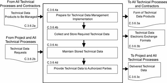
Figure C-15 - Technical Data Management Process
Figure C-16 - Technical Assessment Process
Figure C-17 - Decision Analysis Process
Table G-1 - MCR Entrance and Success Criteria
Table G-2 - SRR/MDR Entrance and Success Criteria
Table G-3 - SDR Entrance and Success Criteria
Table G-4 - PDR Entrance and Success Criteria
Table G-5 - CDR Entrance and Success Criteria
Table G-6 - TRR Entrance and Success Criteria
Table G-7 - SAR Entrance and Success Criteria
Table G-8 - FRR Entrance and Success Criteria
Table G-9 - ORR Entrance and Success Criteria
Table G-10 - DR Entrance and Success Criteria
Please Note: Throughout this document you will find hyperlinks that navigate to other sections of the document and launch new browser windows containing notes for additional explanation of a paragraph or term.
The purpose of this document is to clearly articulate and establish the requirements on the implementing organization for performing, supporting, and evaluating systems engineering. Systems engineering is a logical systems approach performed by multidisciplinary teams to engineer and integrate NASA's systems to ensure NASA products meet customers' needs. Implementation of this systems approach will enhance NASA's core engineering, management, and scientific capabilities and processes to ensure safety and mission success, increase performance, and reduce cost. This systems approach is applied to all elements of a system and all hierarchical levels of a system over the complete project life cycle.
a. This NASA Procedural Requirement (NPR) applies to NASA Headquarters and NASA Centers, including component facilities and technical and service support centers. It also applies to the Jet Propulsion Laboratory to the extent specified in its contracts with NASA. This NPR applies to NASA employees and their service contractors that use NASA processes to augment and support NASA technical work. NASA NPRs and this Systems Engineering NPR (SE NPR) do not apply to NASA contracts except as the NASA technical team flows down the systems engineering responsibilities to all members of the system team including contractors and subcontractors. (See Chapter 4.)
b. The scope of this document encompasses the common technical processes for large and small projects and activities in flight systems and ground support (FS GS) projects, advanced technology development (ATD) projects with deliverables to FS GS projects, information systems and technology projects, and institutional projects (IP). Application of this NPR to Construction of Facilities (CoF) and Environmental Compliance and Restoration (ECR) projects (or portions thereof) should be scaled in accordance with the level of systems engineering for the function of the structure and documented in the systems engineering management plan (SEMP) (as required). In this sense, the design of facilities (or parts of facilities) for processing FS GS would require appropriate application of systems engineering effort, ensuring that interfaces with and functional requirements of the FS GS systems engineering are addressed. The design of administrative facilities or soil remediation projects may not require the application of specific systems engineering efforts. Engineering requirements for CoF and ECR projects are specified in NPR 8820.2 and NPR 8590.1, respectively. Applying the common technical processes and reviews may also benefit basic and applied research (BAR) and other ATD projects. They are recommended but not required for those BAR and ATD projects.
c. In this document, the word "project" generally refers to a unit of work performed in programs, projects, and activities. Management of a work unit is referred to as "project management," which includes managing programs, projects, and activities. A project is (1) A specific investment having defined goals, objectives, requirements, life-cycle cost, a beginning, and an end. A project yields new or revised products or services that directly address NASA's strategic needs. They may be performed wholly in-house; by Government, industry, academia partnerships; or through contracts with private industry. (2) A unit of work performed in programs, projects, and activities.
d. The requirements enumerated in this document are applicable to all new programs and projects as well as all programs and projects currently in Formulation Phase as of the effective date of this document. (See NPR 7120.5 for definitions of program phases.) This NPR also applies to programs and projects in their Implementation ;phase as of the effective date of this document. However, they may request permission from the designated governing authority to be allowed to continue without complying with all or sections of this NPR.
e. Many other discipline areas such as safety, reliability, maintainability, quality assurance, information technology security, logistics, environmental, etc. perform functions during project life-cycle phases that influence or are influenced by the engineering functions performed and need to be fully integrated with the engineering functions. The description of these disciplines and their relationship to the overall management life cycle are defined in other NASA directives, for example, the safety, reliability, maintainability, and quality assurance discipline pertinent requirement activities are defined in the 8700 series of directives.
a. 42 U.S.C. 2473(c)(1), Section 203(c)(1), National Aeronautics and Space Act of 1958, as amended.
b. NPD 1000.0, Strategic Management Governance Handbook.
c. NPD 1000.3, The NASA Organization.
d. NPD 7120.4, Program Project Management.
a. NPD 8700, NASA Safety and Mission Assurance (SMA) Policy documents.
b. NPR 7120.5, NASA Program and Project Management Processes and Requirements.
c. NPD 2820.1, NASA Software Policy.
d. NPR 7150.2, NASA Software Engineering Requirements.
e. NPR 8000.4, Risk Management Procedural Requirements.
f. SP-6105, NASA Systems Engineering Handbook.
g. NPD1080.1 NASA Science Policy.
h. NPR 1080.1 NASA Science Management.
i. NPR 8820.2 Facility Project Implementation Guide.
j. NPD 1440.6, NASA Records Management.
k. NPR 1441.1, NASA Records Retention Schedules.
/S/
Christopher J. Scolese
Chief Engineer
DISTRIBUTION:
NODIS
a. NASA missions are becoming increasingly complex, and the challenge of engineering systems to meet the cost, schedule, and performance requirements within acceptable levels of risk requires revitalizing systems engineering. Functional and physical interfaces are expanding in number and complexity. Software and embedded hardware must be integrated with platforms of varying complexity. Pre-planned project development and the extension of system applications drive higher levels of integration. A driver of increasing system complexity is the significant reduction of operations staff to reduce life-cycle cost and incorporation of their workload into the system. In addition, systems are moving toward increased autonomy with stored knowledge, data gathering, intra- and inter-system communications, and decision-making capabilities.
b. The engineering of NASA systems requires the application of a systematic, disciplined engineering approach that is quantifiable, recursive, iterative, and repeatable for the development, operation, maintenance, and disposal of systems integrated into a whole throughout the life cycle of a project or program. The emphasis of systems engineering is on safely achieving stakeholder functional, physical, and operational performance requirements in the intended use environmentsßover the system's planned life within cost and schedule constraints.
c. While rising to the greater challenge, NASA must also address concerns over past failures. The need for this SE NPR was driven both by past experience and evolving NASA program requirements. Drawing on the result of reports and findings, the Office of the Chief Engineer (OCE) initiated a revitalization of engineering to provide for future missions. This NPR satisfies the component of the revitalization that calls for Agency-level requirements to establish standard technical practices for systems engineering.
d. The vision for systems engineering is to "develop and implement a framework and promote the environment for excellence and the revolutionary advancement of systems engineering capability and projects."to anticipate and meet the needs of NASA programs [1] A robust approach is required to meet the Agency's objectives. Achieving the goal requires systems level thinking on the part of all project participants to accomplish the engineering of NASA systems.
e. This transformation is necessary to provide consistency across the Agency and advance the practice in NASA. This SE NPR will then be applicable to not just the discipline of systems engineering, but the technical teams that perform the activities to engineer the missions for the Agency.
f. This document establishes the common technical processes for implementing NASA products and systems, as directed by NPD 7120.4, Program/Project Management. Additionally, this NPR establishes the common NASA systems engineering technical model and presents tailoring and waiver guidelines. This document complements the administration, management, and review of all programs and projects, as specified in NPR 7120.5, NASA Program and Project Management Processes and Requirements.
1.1.1 Systems engineering at NASA requires the application of a systematic, disciplined engineering approach that is quantifiable, recursive, iterative, and repeatable for the development, operation, maintenance, and disposal of systemsßintegrated into a whole throughout the life cycle of a project or program. The emphasis of systems engineering is on safely achieving stakeholderßfunctional, physical, and operational performance requirements in the intended use environmentsßover the system's planned life within cost and scheduleßconstraints.
1.1.2 This NPRßestablishes a core set of common Agency-level technical processesßand requirements needed to define, develop, realize, and integrate the quality of the systemßproducts created and acquired by or for NASA. The processesßdescribed in this documentßbuild upon and apply best practices and lessons learned from NASA, other governmental agencies, and industry to clearly delineate a successful model to complete comprehensive technical work, reduce program and technical risk, and improve missionßsuccess. The set of common processes in this NPR may be supplemented and tailored to achieve specific project requirements. (See Appendix F. Tailoring.)
1.1.3 Under the lean governance of the updated NPD 1000.0, the relationship of the program/project management and the technical team was clarified to reflect new technical authority. The program/project manager (PM) has overall responsibility for their program/project. The technical team works with and for the PM to accomplish the goals of the project. Due to this updated governance, there is a need to clearly define the role of the systems engineering management plan (SEMP) and how it will be developed. The technical team, working under the overall program management plan (PMP), develops and updates the SEMP as necessary. The technical team works with the PM to review the content and obtain concurrence. This allows for thorough discussion and coordination of how the proposed technical activities would impact the programmatic, cost, and schedule aspects of the project. However, in cases of pure technical issues and for approval of requested waivers to technical requirements, the technical team also has an independent route through the technical designated governing authority (DGA) (as described in Section 2.3) to resolve issues with program/project management. Once all issues are resolved, the PM signs the SEMP. It then goes to the DGA for final signature. The DGA signature assures that an independent review has evaluated the technical aspects of the technical plans and allows for approval of technical waivers or tailoring of the requirements of this NPR and other relevant technical standards that pertain to this NPR.
The order of precedence in case of conflict between requirements is 42 U.S.C. 2473(c)(1), Section 203(c)(1), National Aeronautics and Space Act of 1958, as amended; NPD 1000.0, Strategic Management & Governance Handbook; NPD 1000.3, The NASA Organization; NPD 7120.4, Program/Project Management; and NPR 7123.1, NASA Systems Engineering Processes and Requirements.
In this NPR, a requirement is identified by "shall," a good practice by "should," permission by "may," or "can," expected outcome or action by "will," and descriptive material by "is" or "are" (or another verb form of "to be").
Figures within this NPR are not intended to be prescriptive but notional.
1.2
Framework for Systems Engineering Procedural Requirements
There are three major groupings of requirements within the Office of the Chief Engineer (OCE), i.e., program management requirements, systems engineeringßrequirements, and independent review. This NPR focuses on the systems engineering requirements. (See Appendix E for the hierarchy of related documents.)
1.2.1.1 The common systemsßengineering framework consists of three elements that make up NASA systems engineeringßcapability. The relationship of the three elements is illustrated in Figure 1-1. The integrated implementation of the three elements of the SEßFramework is intended to improve the overall capability required for the efficient and effective engineering of NASA systems. The SEßprocessesßare one element of the larger context to produce quality products and achieve missionßsuccess. This NPRßaddresses the SE processes. The larger SE framework also includes the workforce and tools and methods. OCEßinitiatives to address these other elements include revision of the NASA handbook on systemsßengineering and development of tools and an assessmentßmodel. Together, these elements comprise the capability of an organizationßto perform successful SE. Each element is described below.
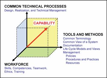
1.2.1.2 Element 1: Common Technical Processes. The common technical processes of this NPR provide what has to be done to engineer system products within a project and why. These processes are applied to the hardware, software, and human parts of a system as one integrated whole. Within this NPR, the contribution of this element to improvement of SE capability is made not only by the common set of technical processes but also by inclusion of:
a. Concepts and terminology that are basic to consistent application and communication of the common technical processes Agency-wide.
b. A structure for when the common technical processes are applied.
1.2.1.3 Element 2: Tools and Methods. Tools and methods enable the efficient and effective completion of theßactivitiesßand tasks of the common technical processes. An essential contribution of this element to SE capability is the improvement of the engineering infrastructure through the three Agency-wide initiatives listed below.
a. Infusion of advanced methods and tools in the SEßprocessesßto achieve greater efficiency, collaboration, and communication among distributed teams.
b. Preparation of a NASA handbook on SEßmethodologies intended to provide a source for various methods and procedures that Centers can draw upon to plan implementation of the required processesßin their projects. This will be an update of the current NASA Systems Engineering Handbook (SP-6105) that will be aligned with NPRß7120.5 and the SE NPR.
c. Creation or adoption of an assessmentßmodel to measure the SEßcapability of projects within NASA and to assess the improvements of capability resulting from implementation of the SE NPR, use of adopted methods and tools, and workforce engineeringßtraining.
1.2.1.4 Element 3: Workforce. A well-trained, knowledgeable, and experienced technical workforce is essential for improving SE capability. The workforce must be able to apply NASA and Center standardized methods and tools for the completion of the required SEßprocessesßwithin the context of the program or project to which they are assigned. In addition, they must be able to effectively communicate requirements and solutions to customers, other engineers, and management to work efficiently and effectively on a team. Issues of recruitment, retention, and trainingßare aspects included in this element. The OCE will facilitate the training of the NASA workforce on the application of this and associated NPRs.
1.2.1.5 SE Capability Together, the three elements of Figure 1-1 comprise an Agency-wide capability to perform successful SE in the engineering of NASA system products.
A SystemsßEngineeringßManagementßPlanß(SEMP) is used to establish the technical content of the engineeringßwork early in the FormulationßPhase for each project and updated throughout the project life cycle. The SEMP provides the specifics of the technical effort and describes what technical processesßwill be used, how the processes will be applied using appropriate activities, how the project will be organized to accomplish the activities, and the cost and scheduleßassociated with accomplishing the activities. The process activities are driven by the critical or key events during any phase of a life cycle (including operations) that set the objectives and work product outputs of the processesßand how the processes are integrated.ß(See Chapter 6 for a description of the SEMP and Appendix D for an annotated outline for the SEMP.) The SEMP provides the communication bridge between the project managementßteam and the technical implementation teams and within technical teams. The SEMP provides the framework to realize the appropriate work products that meet the entry and exit criteriaßof the applicable project life-cycle phases and provides management with necessary information for making decisions.ß
This document is organized into the following chapters.
a. The Preface describes items such as the applicability, scope, authority, and references ofthis SE NPR.
b. The Prologue describes the purpose and vision for this SE NPR.
c. Chapter 1 describes the SEßframework and introduces the SEMP.
d. Chapter 2 describes the institutional and programmatic requirements, including roles and responsibilities.
e. Chapter 3 describes the core set of common Agency-level technical processesßand requirements for engineeringßNASA systemßproducts throughout the product life cycle. Appendix C contains supplemental amplifying material.
f. Chapter 4 describes the activitiesßand requirements to be accomplished by assigned NASA technical teamsßor individuals (NASA employees and their service support contractors)ßwhen performing technical oversight of a prime or external contractor.
g. Chapter 5 describes the technical reviews throughout the SEßlife cycles with clear differentiation between management reviewsßand engineeringßreviews.
h. Chapter 6 describes the SEMPßin general detail, including the SEMP role, functions, and content. Appendix D provides details of a generic SEMP annotated outline.
2.1.1.1 The roles and responsibilities of senior management are defined in part in NPD 1000.0, Strategic Management & Governance Handbook. NPR 7120.5, NASA Program and Project Management Processes and Requirements; NPD 7120.4, Program/Project Management Policies; and other NASA directives define the explicit program/project management responsibilities of program and project managers. This NPR establishes systems engineering processes and responsibilities for their implementation.
2.1.1.2 The OCE under the authority of this SE NPR shall ensure compliance with this SE NPR.
2.1.1.3 For programs and projects involving more than one Center, the lead organization shall develop documentation to describe the hierarchy and reconciliation of Center plans implementing this NPR. The governing mission directorate determines whether a Center executes a project in a lead role or in a peer role. For Centers in peer roles, compliance should be jointly negotiated.
2.1.1.4 For systems that contain software, the technical team shall ensure that software developed internally within NASA or acquired complies with NPD 2820.1, NASA Software Policy and NPR 7150.2, NASA Software Engineering Requirements. Note that NPR 7150.2 elaborates on the requirements in this document and determines the applicability of requirements based on the Agency's software classification. Also note that NPR 7150.2 contains additional Agency requirements for the acquisition, development, maintenance, and management of software.
2.1.1.5 The OCE shall be the clearinghouse for systems engineering policies to ensure compatibility across NASA. In the event of differences between program or project offices and the OCE staff, the conflict will ultimately reach the NASA Chief Engineer or mission director level. If agreement is not achieved at this level, the conflict will be brought to the NASA Administrator for resolution.
2.1.1.6 In this document, the phrase "the Center Directors shall..." means the roles and responsibilities of the Center Directors may be further delegated within the organization as appropriate to the scope and scale of the system.
2.1.2.1 Center Directors oversee and manage the infrastructure for the successful execution of technical authority, support, and assurance of all programs and projects.
2.1.2.2 Center Directors shall perform the following activities or delegate them to the appropriate Center organization:
a. Develop the SE NPR Implementation Plan per the template in Appendix H-1 describing how the requirements of this SE NPR will be applied to the programs and projects under their cognizance or authority.
b. Establish policies, procedures, and processes to execute the requirements of this SE NPR.
c. Assess and take corrective actions to improve the execution of the requirements of this SE NPR.
d. Perform the SE NPR Center Survey in accordance with Appendix H-2 for the purpose of providing feedback on the SE NPR. The initial Center Survey will be submitted nine months from the effective date of this SE NPR. Subsequent updates will be upon the request of the OCE, no earlier than nine months after the initial submission. The Center Survey will use the common survey tool in Appendix H-2 and will be submitted through the Center System Engineering Working Group (SEWG) representative.
e. Select appropriate standards applicable to projects under their control.
Each technical team shall execute the Center processes intended to implement this SE NPR under the oversight of the Center Directors in accordance with the SEMP. The makeup and organization of each technical team is the responsibility of each Center or program and includes the personnel required to implement the project.
2.2
Implementation Architecture
2.2.1.1 Figure 2-1 illustrates the engineering implementation flow and key documents. NPD 7120.4 establishes the policy for engineering and program and project management for the Agency. From that direction, the OCE developed and published this SE NPR, which is consistent and complementary to NPR 7120.5 and other pertinent Agency direction. The requirements established in this SE NPR will flow down to the implementing organizations and Centers.
2.2.1.2 The Center Directors shall submit their SE NPR Implementation Plan to the OCE within six months after the effective date of this NPR. The plan will be updated as required. The SE NPR Implementation Plan will be provided to mission directorates for review and comment. This SE NPR Implementation Plan will be approved by the OCE and include the applicable documents employed by the individual Centers. These Center documents may include Center PRs, work instructions, standards, rules, as well as other Center-unique documentation. The SE NPR is a requirements document that specifies what needs to be accomplished at an Agency level. There will also be a body of knowledge developed to assist in the implementation of the NPR. This body of knowledge will include an updated NASA Systems Engineering Handbook (SP-6105) as well as best practices, standards, and templates.
2.2.1.3 The Centers shall develop and document in the SE NPR Implementation Plan how the particular Center will assess compliance to the SE NPR and provide regular updates to the OCE. In addition, the OCE will conduct periodic updates at the Centers to obtain feedback on the effectiveness of the SE NPR to facilitate updating the NPR.
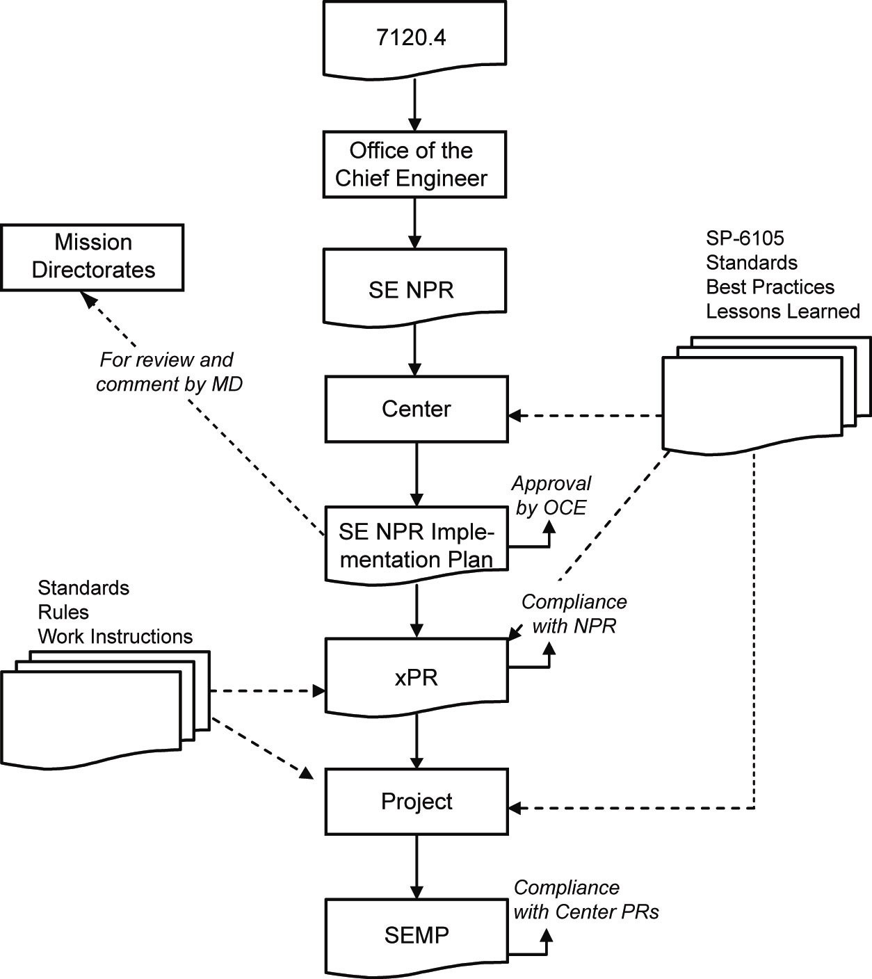
Figure 2-1 - Implementation Architecture
2.3
Designated Governing Authority
The designated governing authority (DGA) for the technical effort in this SE NPR is the Center Director or the person or organization that has been designated by them to ensure the appropriate level of technical management oversight. The DGA is assigned primary responsibility for evaluating the technical content of a particular program or project to ensure that it is meeting the commitments specified in the key management documents. Typically, the DGA is the final approval signature on the Systems Engineering Management Plans, waiver authorizations, and other key technical documents. While overall management of the project SEMPs, technical reviews, and similar project-specific SE products and reviews is the responsibility of the program/project manager, who is expected to sign the documents, the DGA has the final approval signature to ensure independent assessment of technical content and waiver authorizations that pertain to this NPR.
2.3.1.1 The appropriate DGA shall have responsibility to approve or disapprove any SE NPR requirement that is either tailored or waived. Approved tailoring or waivering will be documented in the SEMP, as per the directions provided in appendices D and F.
2.3.1.2 The amount of detail, formality, and rigor required for the implementation of this SE NPR's requirements is tailorable based on the size and complexity of each project and acceptable risk, subject to approval by the project manager and the DGA.
2.3.1.3 A waiver is a documented agreement intentionally releasing a program or project from meeting a requirement. Waivers are required to release a program or project from meeting a requirement in the execution of the processes described in this SE NPR.
3.1.1 This chapter establishes the core set of common technical processes and requirements to be used by NASA projects in engineering system products during applicable product-line life-cycle phases (see Figure 5-1) to meet phase exit criteria and project objectives. The 17 common technical processes are enumerated according to their description in this chapter and their interactions shown in Figure 3-1. This SE common technical processes model illustrates the use of: (1) the system design processes for "top down" design of each product in the system structure, (2) the product realization processes for "bottom up" realization of each product in the system structure, and (3) the technical management processes for planning, assessing, and controlling the implementation of the system design and product realization processes and to guide technical decisionmaking (decision analysis). The SE common technical processes model is referred to as an "SE engine" in this SE NPR to stress that these common technical processes are used to drive the development of the system products and associated work products required by management to satisfy the applicable product-line life-cycle phase exit criteria while meeting stakeholder expectations within cost, schedule, and risk constraints.
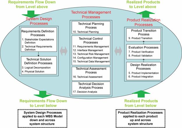
Figure 3-1 - SE Engine
3.1.2.1 The common technical processes are applied to a product-based Work Breakdown Structure (WBS) model to concurrently develop the products that will satisfy the operational or mission functions of the system (end products) and that will satisfy the life-cycle support functions of the system (enabling products). The enabling products facilitate the activities of system design, product realization, operations and mission support, sustainment, and end-of-product life disposal or recycling by having the needed products and services available when needed. (From IEEE 1220, ANSI/EIA 632, ISO/IEC 15288, or ISO/IEC 19760; see Figure 1-1 tools and methods element.)
3.1.2.2 The common technical processes are applied to design a system solution definition for each WBS model down and across each level of the system structure and to realize the WBS model end products up and across the system structure. Figure 3-2 illustrates how the three major sets of processes of the SE Engine (system design processes, product realization processes, and technical management processes) are applied to a WBS model within a system structure (a hierarchy of product-based WBS models). (From IEEE 1220, ANSI/EIA 632, ISO/IEC 15288, or ISO/IEC 19760; see Figure 1-1 tool and methods element.)
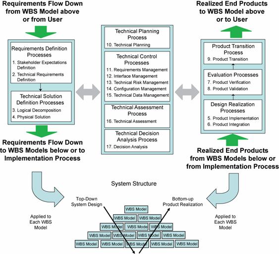
Figure 3-2 - Application of SE Engine Processes within System Structure
3.1.2.3 The common technical processes are used to define the WBS models of the system structure in each applicable phase of the relevant product-line life cycle (see Figure 5-1) to generate work products and system products needed to satisfy the exit criteria of the applicable phase. System engineering continues well into the operations and maintenance phase of a project, i.e., after the system products are delivered. For example, in the course of operating, maintaining, and disposing of an existing system, all upgrades, enhancements, supporting or enabling developments, and reconfigurations must apply the common SE technical processes. (From ISO/IEC 15288 and ANSI/EIA 632.)
3.1.2.4 The common technical processes are applied by assigned technical teams and individuals of the NASA workforce trained in the requirements of this SE NPR.
3.1.2.5 The assigned technical teams and individuals should use the appropriate and available sets of tools and methods to accomplish required common technical process activities. This would include the use of modeling and simulation as applicable to the product-line phase, location of the WBS model in the system structure, and the applicable phase exit criteria.
3.1.3 The assigned technical teams shall define in the project SEMP how the required 17 common technical processes, as implemented by Center documentation, will be applied to the various levels of project WBS model system structure during each applicable life-cycle phase and have their approach approved by the DGA.
For the statements below "establish" means developing policy, work instructions, or procedures to implement process activities. "Maintain" includes planning the process, providing resources, assigning responsibilities, training people, managing configurations, identifying and involving stakeholders, and monitoring and controlling the process.
3.2.1.1 The Center Directors or designees shall establish and maintain a process, to include activities, requirements, guidelines, and documentation, for the definition of stakeholder expectations for the applicable WBS model.
3.2.1.2 The stakeholder expectations definition process is used to elicit and define use cases, scenarios, operational concepts, and stakeholder expectations for the applicable product-line life-cycle phases and WBS model. This includes requirements for: (a) operational end products and life-cycle-enabling products of the WBS model; (b) expected skills and capabilities of operators or users; (c) expected number of simultaneous users, (d) system and human performance criteria, (e) technical authority, standards, regulations, and laws; (f) factors such as safety, quality, security, context of use by humans, reliability, availability, maintainability, electromagnetic compatibility, interoperability, testability, transportability, supportability, usability, and disposability; and (g) local management constraints on how work will be done (e.g., operating procedures). The baselined stakeholder expectations are used for validation of the WBS model end product during product realization
3.2.1.3 Typical practices of this process are defined in Appendix C.1.1.
3.2.2.1 The Center Directors or designees shall establish and maintain a process, to include activities, requirements, guidelines, and documentation, for definition of the technical requirements from the set of agreed to stakeholder expectations for the applicable WBS model.
3.2.2.2 The technical requirements definition process is used to transform the baselined stakeholder expectations into unique, quantitative, and measurable technical requirements expressed as "shall" statements that can be used for defining a design solution definition for the WBS model end product and related enabling products.
3.2.2.3 Typical practices of this process are defined in Appendix C.1.2.
3.2.3.1 The Center Directors or designees shall establish and maintain a process, to include activities, requirements, guidelines, and documentation, for logical decomposition of the validated technical requirements of the applicable WBS model.
3.2.3.2 The logical decomposition process is used to improve understanding of the defined technical requirements and the relationships among the requirements (e.g., functional, behavioral, and temporal) and to transform the defined set of technical requirements into a set of logical decomposition models and their associated set of derived technical requirements for input to the design solution definition process.
3.2.3.3 Typical practices of this process are defined in Appendix C.1.3.
3.2.4.1 The Center Directors or designees shall establish and maintain a process, to include activities, requirements, guidelines and documentation, for designing product solution definitions within the applicable WBS model that satisfy the derived technical requirements.
3.2.4.2 The design solution definition process is used to translate the outputs of the logical decomposition process into a design solution definition that is in a form consistent with the product-line life-cycle phase and WBS model location in the system structure and that will satisfy phase exit criteria. This includes transforming the defined logical decomposition models and their associated sets of derived technical requirements into alternative solutions, then analyzing each alternative to be able to select a preferred alternative, and fully defining that alternative into a final design solution definition that will satisfy the technical requirements. These design solution definitions will be used for generating either end products by using the product implementation process or product integration process as a function of the position of the WBS model in the system structure and whether there are additional subsystems of the end product that need to be defined. The output definitions from the design solution (end product specifications) will be used for conducting product verification.
3.2.4.3 Typical practices of this process are defined in Appendix C.1.4.
3.2.5.1 The Center Directors or designees shall establish and maintain a process, to include activities, requirements, guidelines, and documentation, for implementation of a design solution definition by making, buying, or reusing an end product of the applicable WBS model.
3.2.5.2 The product implementation process is used to generate a specified product of a WBS model through buying, making or reusing in a form consistent with the product-line life-cycle phase exit criteria and that satisfies the design solution definition specified requirements (e.g., drawings, specifications).
3.2.5.3 Typical practices of this process are defined in Appendix C.2.1
3.2.6.1 The Center Directors or designees shall establish and maintain a process to include activities, requirements, guidelines, and documentation for the integration of lower-level products into an end product of the applicable WBS model in accordance with its design solution definition.
3.2.6.2 The product integration process is used to transform the design solution definition into the desired end product of the WBS model through assembly and integration of lower-level validated end products, in a form consistent with the product-line life-cycle phase exit criteria and that satisfies the design solution definition requirements (e.g., drawings, specifications).
3.2.6.3 Typical practices of this process are defined in Appendix C.2.2.
3.2.7.1 The Center Directors or designees shall establish and maintain a process, to include activities, requirements, guidelines, and documentation, for verification of end products generated by the product implementation process or product integration process against their design solution definitions.
3.2.7.2 The product verification process is used to demonstrate that an end product generated from product implementation or product integration conforms to its design solution definition requirements as a function of the product-line life-cycle phase and the location of the WBS model end product in the system structure. Special attention is given to demonstrating satisfaction of the measures of performance (MOPs) defined for each measure of effectiveness (MOE) during conduct of the technical requirements definition process.
3.2.7.3 Typical practices of this process are defined in Appendix C.2.3.
3.2.8.1 The Center Directors or designees shall establish and maintain a process, to include activities, requirements, guidelines, and documentation, for validation of end products generated by the product implementation process or product integration process against their stakeholder expectations.
3.2.8.2 The product validation process is used to confirm that a verified end product generated by product implementation or product integration fulfills (satisfies) its intended use when placed in its intended environment and ensure that any anomalies discovered during validation are appropriately resolved prior to delivery of the product (if validation is done by the supplier of the product) or prior to integration with other products into a higher-level assembled product (if validation is done by the receiver of the product). The validation is done against the set of baselined stakeholder expectations. Special attention should be given to demonstrating satisfaction of the MOEs identified during conduct of the stakeholder expectations definition process. The type of product validation is a function of the form of the product, product-line life-cycle phase, and in accordance with an applicable customer agreement.
3.2.8.3 Typical practices of this process are defined in Appendix C.2.4.
3.2.9.1 The Center Directors or designees shall establish and maintain a process, to include activities, requirements, guidelines and documentation, for transitioning end products to the next level up WBS model customer or user.
3.2.9.2 The product transition process is used to transition a verified and validated end product that has been generated by product implementation or product integration to the customer at the next level in the system structure for integration into an end product or, for the top level end product, transitioned to the intended end user. The form of the product transitioned will be a function of the product-line life-cycle phase exit criteria and the location within the system structure of the WBS model in which the end product exits.
3.2.9.3 Typical practices of this process are defined in Appendix C.2.5.
3.2.10.1 The Center Directors or designees shall establish and maintain a process, to include activities, requirements, guidelines, and documentation, for planning the technical effort.
3.2.10.2 The technical planning process is used to plan for the application and management of each common technical process and to identify, define, and plan the technical effort applicable to the product-line life-cycle phase, for WBS model location within the system structure, and to meet project objectives and product-line life-cycle phase exit criteria. A key document generated by this process is the SEMP. (See Chapter 6.)
3.2.10.3 Typical practices of this process are defined in Appendix C.3.1.
3.2.11.1 The Center Directors or designees shall establish and maintain a process, to include activities, requirements, guidelines, and documentation, for management of requirements defined and baselined during the application of the system design processes.
3.2.11.2 The requirements management process is used to: (a) manage the product requirements identified, baselined, and used in the definition of the WBS model products during system design; (b) provide bidirectional traceability back to the top WBS model requirements and (c) manage the changes to established requirement baselines over the life cycle of the system products.
3.2.11.3 Typical practices of this process are defined in Appendix C.3.2.
3.2.12.1 The Center Directors or designees shall establish and maintain a process, to include activities, requirements, guidelines, and documentation, for management of the interfaces defined and generated during the application of the system design processes.
3.2.12.2 The interface management process is used to (a) establish and use formal interface management to assist in controlling system product development efforts when the efforts are divided between Government programs, contractors, and/or geographically diverse technical teams within the same program or project and (b) maintain interface definition and compliance among the end products and enabling products that compose the system, as well as with other systems with which the end products and enabling products must interoperate.
3.2.12.3 Typical practices of this process are defined in Appendix C.3.3.
3.2.13.1 The Center Directors or designees shall establish and maintain a process, to include activities, requirements, guidelines, and documentation for management of the technical risk identified during the technical effort. (NPR 8000.4, Risk Management Procedural Requirements is to be used as a source document for defining this process, and NPR 8705.5, Probabilistic Risk Assessment (PRA) Procedures for NASA Programs and Projects, provides one means of identifying and assessing technical risk.)
3.2.13.2 The technical risk management process is used to examine on a continuing basis the risks of technical deviations from the project plan and identify potential technical problems before they occur so that risk-handling activities can be planned and invoked as needed across the life of the product or project to mitigate impacts on achieving product-line life-cycle phase exit criteria and meeting technical objectives.
3.2.13.3 Typical practices of this process are defined in Appendix C.3.4.
3.2.14.1 The Center Directors or designees shall establish and maintain a process, to include activities, requirements, guidelines, and documentation, for configuration management.
3.2.14.2 The configuration management process for end products, enabling products, and other work products placed under configuration control is used to (a) identify the configuration of the product or work product at various points in time; (b) systematically control changes to the configuration of the product or work product; (c) maintain the integrity and traceability of the configuration of the product or work product throughout its life; and (d) preserve the records of the product or end product configuration throughout its life cycle, dispositioning them in accordance with NPR 1441.1, NASA Records Retention Schedules.
3.2.14.3 Typical practices of this process are defined in Appendix C.3.5.
3.2.15.1 The Center Directors or designees shall establish and maintain a process, to include activities, requirements, guidelines, and documentation, for management of the technical data generated and used in the technical effort.
3.2.15.2 The technical data management process is used (a) to provide the basis for identifying and controlling data requirements; (b) to responsively and economically acquire, access, and distribute data needed to develop, manage, operate, and support system products over their product-line life; (c) to manage and disposition data as records; (d) to analyze data use; (e)if any of the technical effort is performed by an external contractor, to obtain technical data feedback for managing the contracted technical effort; and (f) to assess the collection of appropriate technical data and information.
3.2.15.3 Typical practices of this process are defined , in , , Appendix C.3.6. ,
3.2.16.1 The Center Directors or designees shall establish and maintain a process, to include activities, requirements, guidelines, and documentation, for making assessments of the progress of planned technical effort and progress toward requirements satisfaction.
3.2.16.2 The technical assessment process is used to help monitor progress of the technical effort and provide status information for support of the system design, product realization, and technical management processes.
3.2.16.3 Typical practices of this process are defined in, Appendix C.3.7.
3.2.17.1 The Center Directors or designees shall establish and maintain a process, to include activities, requirements, guidelines and documentation, for making technical decisions.
3.2.17.2 The decision analysis process, including data collection (e.g., engineering performance, quality, and reliability data), is used to help evaluate technical decision issues, technical alternatives, and their uncertainties to support decisionmaking. This process is used throughout technical management, system design, and product realization processes to evaluate the impact of decisions on performance, cost, schedule, and technical risk.
3.2.17.3 Typical practices of this process are defined in Appendix C.3.8.
4.1.1 Oversight/insight of projects where prime or external contractors do the majority of the development effort has always been an important part of NASA programs and projects. With the new focus on Exploration and Space missions such projects will not only increase but it will become more critical that NASA projects provide increased systems engineering on these projects before, during, and after contract performance.
4.1.2 This chapter defines a minimum set of technical activities and requirements for a NASA project technical team to perform on projects where prime or external contractors do the majority of the development effort before contract award, during contract performance, and upon completion of the contract. These activities and requirements are intended to supplement the common technical process activities and requirements of Chapter 3 and thus enhance the outcome of the contracted effort.
4.2.1 The assigned NASA technical team< shall prepare a SEMP that covers the periods before contract award, during contract performance, and upon contract completion in accordance with content contained in the annotated outline in Appendix D.
4.2.2 The assigned technical team shall use common technical processes, as implemented by the Center's documentation, to establish the technical inputs, which include product requirements and Statement of Work tasks, to the Request for Proposal (RFP) appropriate for the product to be developed.
4.2.3 The technical team shall determine the technical work products to be delivered by the offeror or contractor to include a contractor SEMP that specifies their systems engineering approach for requirements development, technical solution definition, design realization, product evaluation, product transition, and technical planning, control, assessment, and decision analysis.
4.2.4 The technical team shall provide to the contracting officer, for inclusion in the RFP, the requirements for technical oversight activities planned in the NASA SEMP. (Care should be taken that no requirements or solicitation information is divulged prior to the release of the solicitation by the cognizant contracting officer.)
4.2.5 The technical team shall participate in the evaluation of offeror proposals following applicable NASA and Center source selection procedures.
4.3.1 The assigned technical team, under the authority of the cognizant contracting officer, shall perform the technical oversight activities established in the NASA SEMP.
4.4.1 The assigned technical team shall participate in scheduled milestone reviews to finalize Government acceptance of the deliverables.
4.4.2 The assigned technical team shall participate in product transition to the customer and/or disposal as defined in the NASA SEMP.
Chapter 5. Systems Engineering Technical Reviews
5.1.1 NASA has four interrelated product lines as defined by 7120.5: Basic and Applied Research (BAR); Advanced Technology Development (ATD); Flight System and Ground Support (FS GS) projects; and Institutional Projects (IP). As shown in Figure 5-1, each product line has its own unique product-line life cycle. Figure 5-1 shows the product-line life cycles and technical reviews mapped into the management life cycle.
5.1.2 The product-line life cycle for a typical BAR project begins in the "Preparation of Portfolio" phase and eventually ends with a "Monitor Performance Metrics" phase.
5.1.3 The ATD management life cycle for a typical ATD project begins in the "Concept Study" phase and eventually ends with "Technology Readiness Level Maturation" and "Key Performance Parameters (KPP) Enhancements" phases.
5.1.4 The FS GS project management life cycle starts with "Concept Studies," progresses into a "Concept Development" phase, and eventually ends after its "Operations and Sustainment" phase with a "Disposal" phase.
5.1.5 The IP management life cycle proceeds through their capital assets life cycle in five well-defined phases. An IP project starts with a "Pre-Formulation and Proposal" phase, progresses into a "Preliminary Design" phase, and eventually ends after "Operations and Maintenance" with a "Disposal" phase. For non-capital asset projects, the last three phases are replaced by an "Execute Project Plan" phase. Typically, these projects enable all of the other NASA investment areas and product lines.
5.1.6 The two major common phases for all of the product linesare Formulationand Implementation. Within each product line, the specific phases are appropriate to their product lines. FSGS projects have two variations-traditional flight systems development and Announcement of Opportunity (AO) projects.
5.1.7 The life-cycle phases in which the SE engine is applied and the technical reviews of this chapter are closely linked to the management life-cycle phases of NPR 7120.5. The application of the common technical processes within each life-cycle phase produce technical results that provide inputs to technical reviews and support informed management decisions for progressing to the next product-line life-cycle phase.
5.1.8 At each management decision gate, one of the key questions is whether the project is ready to proceed to the next product-line phase (i.e., from Phase B to Phase C). At each decision gate, management examines the maturity of the technical aspects of the project; for example, whether the resources (staffing, funding) are sufficient for the planned technical effort, whether the technical maturity has evolved, what the technical and non-technical internal issues and risks are; or whether the stakeholder expectations have changed. If the technical and management aspects of the project are satisfactory and corrective actions are implementable, then the project can be approved to proceed to the next phase.
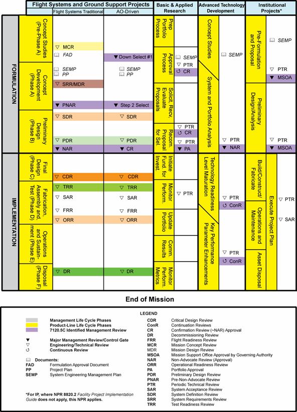
Figure 5-1 - Product Line Life Cycle
5.1.9 Three points are important: (1) Management reviews and the technical reviews support one another. (2) Technical reviews are completed before a management decision gate. (3) Technical reviews should occur relative to the maturity of the relevant technical baseline as opposed to calendar milestones (e.g., the quarterly progress review, the yearly summary, etc.).
5.2.1.1 For each product line (BAR, ATD, IP, and FS GS), technical efforts are monitored throughout the life cycle to ensure that the technical goals of the project are being achieved and that the technical direction of the project is appropriate.
5.2.1.2 Technical teams shall monitor technical effort through periodic technical reviews. (See Technical Assessment Process Appendix C.3.7.4.d.)
5.2.1.3 A technical review is an evaluation of the project, or element thereof, by a knowledgeable group for the purposes of:
a. Assessing the status of and progress toward accomplishing the planned activities.
b. Validating the technical tradeoffs explored and design solutions proposed.
c. Identifying technical weaknesses or marginal design and potential problems (risks) and recommending improvements and corrective actions.
d. Making judgments on the activities' readiness for the follow-on events including additional future evaluation milestones to improve the likelihood of a successful outcome.
e. Making assessments and recommendations to the project team, Center, and Agency management.
f. Providing a historical record that can be referenced of decisions that were made during these formal reviews.
5.2.1.4 See NPR 7120.5 for a description of independent reviews, major reviews, project milestone reviews, and engineering peer reviews.
5.2.1.5 The set of minimum reviews is used to evaluate the status of the technical progress and is supported by other equivalent technical discipline activities to include safety reviews.
5.2.1.6 The technical team shall ensure that system aspects represented or implemented in software are included in all technical reviews to demonstrate that project technical goals and progress are being achieved and that all NPR 7150.2 software review requirements are implemented.
The technical team shall develop and document plans for technical reviews for use in the project planning process. The technical review schedule will be reflected in the overall project plan described in NPR 7120.5. The results of each technical review will be used to update the technical review plan as part of the SEMP update process. The review plans, data, and results should be maintained and dispositioned as Federal records.
5.3.1.1 Figure 5-1 maps specific reviews and their time sequence for each product line. These reviews are event based, held prior to management reviews when progressing from one life-cycle phase to the next. A description and representative entrance and success criteria for each of these reviews are contained in Appendix G. Additional description of technical reviews is provided in NASA Systems Engineering Handbook (SP-6105).
5.3.1.2 The monitoring function for traditional FS GS projects shall be accomplished using the following required minimum set of technical reviews: Mission Concept Review (MCR) , System Requirements Review (SRR) and/or Mission Definition Review (MDR), System Definition Review (SDR), Preliminary Design Review (PDR), Critical Design Review (CDR), Test Readiness Review (TRR), System Acceptance Review (SAR), Flight Readiness Review (FRR), Operational Readiness Review (ORR), and Decommissioning Review (DR). Programs would typically hold FRR, ORR, and DRs with support as required from the projects.
5.3.1.3 The assigned technical team shall accomplish the monitoring function for flight-related ATD projects using appropriately defined and conducted periodic technical reviews (PTR).
5.3.1.4 The assigned technical team shall accomplish the monitoring function for IPs using PTRand SAR.
5.3.1.5 SP 6105, NASA Systems Engineering Handbook, provides a complete description of additional common technical progress reviews (interim reviews) with entrance and success criteria, as well as timing, key products, success criteria, etc.
5.3.1.6 Reviews are considered complete when the following is accomplished:
a. Agreement exists for the disposition of all Review Item Discrepancies (RID) and Request for Actions (RFA).
b. The review board report and minutes are complete and distributed.
c. Agreement exists on a plan to address the issues and concerns in the review board's report.
d. Agreement exists on a plan for addressing the actions identified out of the review.
e. Liens against the review results are closed, or an adequate and timely plan exists for their closure.
f. Differences of opinion between the project under review and the review board(s) have been resolved, or a timely plan exists to resolve the issues.
g. A report is given by the review board chairperson to the appropriate management and governing program management committees (GPMCs) charged with oversight of the project.
h. Appropriate procedures and controls are instituted to ensure that all actions from reviews are followed and verified through implementation to closure.
6.1.1 The primary function of the SEMP is to provide the basis for implementing the technical effort and communicating what will be done, by whom, when, where, cost drivers, and why it is being done. In addition, the SEMP identifies the roles and responsibility interfaces of the technical effort and how those interfaces will be managed.
6.1.2 The SEMP is the vehicle that documents and communicates the technical approach including the application of the common technical processes; resources to be used; and key technical tasks, activities, and events along with their metrics and success criteria. The SEMP communicates the technical effort that will be performed by the assigned technical team to the team itself, managers, customers, and other stakeholders. Whereas the primary focus is on the applicable phase in which the technical effort will be done, the planning extends to a summary of the technical efforts that are planned for future applicable phases.
6.1.3 TheSEMP is a "living" and tailorable document that captures a project's current and evolving systems engineering strategy and its relationship with the overall project management effort throughout the life cycle of the system. The SEMP's purpose is to guide all technical aspects of the project.
6.1.4 The SEMP is consistent with higher level SEMPs and the project plan in accordance with NPR 7120.5.
6.1.5 The content of a SEMP for an in-house technical effort may differ from an external technical effort. For an external technical effort, the SEMP should include details on developing requirements for source selection, monitoring performance, and transferring and integrating externally produced products to NASA. (See Appendix D for further details.)
6.1.6 The SEMP provides the basis for generating the contractor engineering plan.
6.2.1 Working with the program/project manager, the technical team shall determine the appropriate level within the system structure at which SEMPs are developed, taking into account factors such as number and complexity of interfaces, operating environments, and risk factors.
6.2.2 The technical team shall baseline the SEMP per the Center's Implementation Plan incorporating the content contained in Appendix D Systems Engineering Management Plan, prior to completion of Phase A in the program life cycle or the equivalent milestone. At the discretion of the PM and the DGA, for a small project the material in the SEMP can be placed in the project plan's technical summary and the annotated outline in Appendix D used as a topic guide. As changes occur, the SEMP will be updated by the technical team, reviewed and concurred with by the PM, and presented at subsequent milestone reviews or their equivalent.
6.2.3 The DGA shall review and approve or disapprove the SEMP at each major milestone review or its equivalent.
6.2.4 The assigned technical team shall establish the initial SEMP early in the Formulation Phase and update as necessary to reflect changes in scope or improved technical development.
6.2.5 The technical team shall ensure that any technical plans and discipline plans describe how the technical activities covered in the plans are consistent with the SEMP and are accomplished as fully integrated parts of the technical effort.
6.2.6 The technical team shall ensure that the project's software development/management plan describes how the software activities are consistent with the SEMP and are accomplished as fully integrated parts of the technical effort. The required content of the project's software development/management plan is provided in NPR 7150.2, dependent upon the classification of software items.
A.1 Activity: (1)Any of the project components or research functions that are executed to deliver a product or service or provide support or insight to mature technologies. (2) A set of tasks that describe the technical effort to accomplish a process and help generate expected outcomes.
A.2 Advanced Technology Development: ATD is one of four interrelated NASA product lines. ATD programs and projects are investments that produce entirely new capabilities or that help overcome technical limitations of existing systems. ATD is seen as a bridge between BAR and actual application in NASA, such as FS GS projects or elsewhere. ATD projects typically fall within a Technology Readiness Level (TRL) range of 4 to 6.
A.3 Baseline: An agreed-to set of requirements, designs, or documents that will have changes controlled through a formal approval and monitoring process.
A.4 Basic and Applied Research: Research whose results expand the knowledge base, provide scientific and technological breakthroughs that are immediately applicable, or evolve into an advanced technology development (ATD). Basic research addresses the need for knowledge, while applied research directs this new knowledge toward a practical application.
A.5 Component Facilities: Complexes that are geographically separated from the NASA Center or institution to which they are assigned.
A.6 Contractor: For the purposes of this NPR, a "contractor" is an individual, partnership, company, corporation, association, or other service having a contract with the Agency for the design, development, manufacture, maintenance, modification, operation, or supply of items or services under the terms of a contract to a program or project within the scope of this NPR. Research grantees, research contractors, and research subcontractors are excluded from this definition.
A.7 Critical Event (also referred to as a Key Event in this NPR): An event that requires monitoring in the projected life cycle of a product that will generate critical requirements that would affect system design, development, manufacture, test, and operations (such as with an MOE, MOP, TPM, or KPP).
A.8 Customer: The organization or individual that has requested a product and will receive the product to be delivered. The customer may be an end user of the product, the acquiring agent for the end user, or the requestor of the work products from a technical effort. Each product within the system hierarchy has a customer.
A.9 Designated Governing Authority: The management entity above the program, project, or activity level with technical oversight responsibility.
A.10 Enabling Products: The life-cycle support products and services (e.g., production, test, deployment, training, maintenance, and disposal) that facilitate the progression and use of the operational end product through its life cycle. Since the end product and its enabling products are interdependent, they are viewed as a system. Project responsibility thus extends to responsibility for acquiring services from the relevant enabling products in each life-cycle phase. When a suitable enabling product does not already exist, the project that is responsible for the end product can also be responsible for creating and using the enabling product.
A.11 Engine: The SE model shown in Figure 3-1 provides the 17 technical processes and their relationship with each other. The model is called an "SE engine" in that the appropriate set of processes are applied to the products being engineered to drive the technical effort.
A.12 Entry Criteria: Minimum accomplishments each project needs to fulfill to enter into the next life-cycle phase or level of technical maturity.
A.13 Establish (with respect to each process in Chapter 3): The act of developing policy, work instructions or procedures to implement process activities.
A.14 Exit Criteria: Specific accomplishments that should be satisfactorily demonstrated before a project can progress to the next product-line life-cycle phase.
A.15 Expectation: Statements of needs, desires, capabilities and wants that are not expressed as a requirement (not expressed as a "shall" statement) is to be referred to as an "expectation." Once the set of expectations from applicable stakeholders is collected, analyzed, and converted into a "shall" statement, the "expectation" becomes a "requirement." Expectations can be stated in either qualitative (non-measurable) or quantitative (measurable) terms. Requirements are always stated in quantitative terms. Expectations can be stated in terms of functions, behaviors, or constraints with respect to the product being engineered or the process used to engineer the product.
A.16 Flight Systems and Ground Support: FS&GS is one of four interrelated NASA product lines. FS&GS projects result in the most complex and visible of NASA investments. To manage these systems, the Formulation and Implementation phases for FS&GS projects follow the NASA project life-cycle model consisting of phases A (Concept Development) through F (Disposal). Primary drivers for FS&GS projects are safety and mission success.
A.17 Formulation Phase: The first part of the NASA management life cycle defined in NPR 7120.5 where system requirements are baselined, feasible concepts are determined, a system definition is baselined for the selected concept(s), and preparation is made for progressing to the Implementation Phase.
A.18 Implementation Phase: The part of the NASA management life cycle defined in NPR 7120.5 where the detailed design of system products is completed and the products to be deployed are fabricated, assembled, integrated and tested; and the products are deployed to their customers or users for their assigned use or mission.
A.19 Institutional Projects: Projects that build or maintain the institutional infrastructure to support other NASA product lines.
A.20 Information Systems and Technology Projects: All NASA projects for or including the development, modernization, enhancement, or steady-state operations of information systems and technologies. This includes projects for or containing computer and/or communications systems, ancillary equipment, hardware, software applications, firmware, or networks for the generation, processing, storage, access, manipulation, exchange or safeguarding of information.
A.21 Iterative: Application of a process to the same product or set of products to correct a discovered discrepancy or other variation from requirements. (See "recursive" and "repeatable.")
A.22 Key Event: See Critical Event.
A.23 Key Performance Parameters: Those capabilities or characteristics (typically engineering-based or related to safety or operational performance) considered most essential for successful mission accomplishment. Failure to meet a KPP threshold can be cause for the project, system, or advanced technology development to be reevaluated or terminated or for the system concept or the contributions of the individual systems to be reassessed. A project's KPPs are identified and quantified in the project baseline. (See Technical Performance Parameter.)
A.24 Logical Decomposition: The decomposition of the defined technical requirements by functions, time, and behaviors to determine the appropriate set of logical models and related derived technical requirements. Models may include functional flow block diagrams, timelines, data control flow, states and modes, behavior diagrams, operator tasks, and functional failure modes.
A.25 Maintain (with respect to establishment of processes in Chapter 3): The act of planning the process, providing resources, assigning responsibilities, training people, managing configurations, identifying and involving stakeholders, and monitoring process effectiveness.
A.26 Measure of Effectiveness: A measure by which a stakeholder's expectations will be judged in assessing satisfaction with products or systems produced and delivered in accordance with the associated technical effort. The MOE is deemed to be critical to not only the acceptability of the product by the stakeholder but also critical to operational/mission usage. An MOE is typically qualitative in nature or not able to be used directly as a "design-to" requirement.
A.27 Measure of Performance: A quantitative measure that, when met by the design solution, will help ensure that an MOE for a product or system will be satisfied. These MOPs are given special attention during design to ensure that the MOEs to which they are associated are met. There are generally two or more measures of performance for each MOE.
A.28 Non-Advocate Review: The analysis of a proposed project by a non-advocate team composed of management, technical, and budget experts from outside the advocacy chain of the proposed project. The NAR provides Agency management with an independent assessment of the readiness of the project to proceed into implementation.
A.29 Other Interested Parties: A subset of "stakeholders," other interested parties are groups or individuals that are not customers of a planned technical effort but may be affected by the resulting product, the manner in which the product is realized or used, or have a responsibility for providing life-cycle support services. A subset of "stakeholders." (See Stakeholder.)
A.30 Peer Review: Independent evaluation by internal or external subject matter experts who do not have a vested interest in the work product under review. Peer reviews can be planned, focused reviews conducted on selected work products by the producer's peers to identify defects and issues prior to that work product moving into a milestone review or approval cycle.
A.31 Process: A set of activities used to convert inputs into desired outputs to generate expected outcomes and satisfy a purpose.
A.32 Product: A part of a system consisting of end products that perform operational functions and enabling products that perform life-cycle services related to the end product or a result of the technical efforts in the form of a work product (e.g., plan, baseline, or test result).
A.33 Product-Based WBS Model: See WBS model.
A.34 Product Realization: The act of making, buying, or reusing a product, or the assembly and integration of lower level realized products into a new product, as well as the verification and validation that the product satisfies its appropriate set of requirements and the transition of the product to its customer.
A.35 Program: A strategic investment by a mission directorate (or mission support office) that has defined goals, objectives, architecture, funding level, and a management structure that supports one or more projects.
A.36 Program Commitment Agreement: The contract between the Administrator and the cognizant Mission Directorate Associate Administrator (MDAA) or Mission Support Office Director (MSOD) for implementation of a program.
A.37 Project: (1) A specific investment having defined goals, objectives, requirements, life-cycle cost, a beginning, and an end. A project yields new or revised products or services that directly address NASA's strategic needs. They may be performed wholly in-house; by Government, industry, academia partnerships; or through contracts with private industry. (2) A unit of work performed in programs, projects, and activities.
A.38 Realized Product: The desired output from the application of the four Product Realization Processes. The form of this product is dependent on the phase of the product-line life cycle and the phase exit criteria.
A.39 Recursive: Value is added to the system by the repeated application of processes to design next lower layer system products or to realize next upper layer end products within the system structure. This also applies to repeating application of the same processes to the system structure in the next life-cycle phase to mature the system definition and satisfy phase exit criteria.
A.40 Relevant Stakeholder: See Stakeholder.
A.41 Repeatable: A characteristic of a process that can be applied to products at any level of the system structure or within any life- cycle phase.
A.42 Requirement: The agreed upon need, desire, want, capability, capacity, or demand for personnel, equipment, facilities, or other resources or services by specified quantities for specific periods of time or at a specified time expressed as a "shall" statement. Acceptable form for a requirement statement is individually clear, correct, feasible to obtain, unambiguous in meaning, and can be validated at the level of the system structure at which stated. In pairs of requirement statements or as a set, collectively, they are not redundant, are adequately related with respect to terms used, and are not in conflict with one another.
A.43 Risk: The combination of the probability that a program or project will experience an undesired event (some examples include a cost overrun, schedule slippage, safety mishap, health problem, malicious activities, environmental impact, failure to achieve a needed scientific or technological breakthrough or mission success criteria) and the consequences, impact, or severity of the undesired event, were it to occur. Both the probability and consequences may have associated uncertainties. (Reference 7120.5.)
A.44 Software: As defined in NPD 2820.1, NASA Software Policy.
A.45 Specification: A document that prescribes, in a complete, precise, verifiable manner, the requirements, design, behavior, or characteristics of a system or system component.
A.46 Stakeholder: A group or individual who is affected by or is in some way accountable for the outcome of an undertaking. The term "relevant stakeholder" is a subset of the term "stakeholder" and describes people or roles that are designated in a plan for stakeholder involvement. Since "stakeholder" may describe a very large number of people, a lot of time and effort would be consumed by attempting to deal with all of them. For this reason, "relevant stakeholder" is used in most practice statements to describe the people identified to contribute to a specific task. There are two main classes of stakeholders. See "customers" and "other interested parties."
A.47 Success Criteria: Specific accomplishments that must be satisfactorily demonstrated to meet the objectives of a technical review so that a technical effort can progress further in the life cycle. Success criteria are documented in the corresponding technical review plan.
A.48 Surveillance-Type Projects: A project where prime or external contractors do the majority of the development effort that requires NASA oversight.
A.49 System: A system is: (a) The combination of elements that function together to produce the capability to meet a need. The elements include all hardware, software, equipment, facilities, personnel, processes, and procedures needed for this purpose. (reference NPR 7120.5) (b) The end product (performs operational functions) and enabling products (provide life-cycle support services to the operational end products) that make up a system. (See WBS definition.)
A.50 Systems Approach: The application of a systematic, disciplined engineering approach that is quantifiable, recursive, iterative, and repeatable for the development, operation, and maintenance of systems integrated into a whole throughout the life cycle of a project or program.
A.51 Systems Engineering Management Plan: The SEMP identifies the roles and responsibility interfaces of the technical effort and how those interfaces will be managed. The SEMP is the vehicle that documents and communicates the technical approach, including the application of the common technical processes; resources to be used; and key technical tasks, activities, and events along with their metrics and success criteria.
A.52 System Safety Engineering: The application of engineering and management principles, criteria, and techniques to achieve acceptable mishap risk, within the constraints of operational effectiveness and suitability, time, and cost, throughout all phases of the system life cycle.
A.53 System Structure: A system structure is made up of a layered structure of product-based WBS models. (See WBS definition.)
A.54 Tailoring: The
documentation and approval of the adaptation of the process and
approach to complying with requirements underlying the specific program or
projects. (Adapted from NPR 7120.5.) Tailoring considerations include
system size and complexity, level of system definition detail, scenarios
and missions, constraints and requirements, technology base, major risk
factors, and organizational best practices and strengths. (From Systems
Engineering Fundamentals,
A.55 Technical Performance Measures: The set of critical or key performance parameters that are monitored by comparing the current actual achievement of the parameters with that anticipated at the current time and on future dates. Used to confirm progress and identify deficiencies that might jeopardize meeting a system requirement. Assessed parameter values that fall outside an expected range around the anticipated values indicate a need for evaluation and corrective action. Technical performance measures are typically selected from the defined set of Measures of Performance (MOPs).
A.56 Technical Team: A group of multidisciplinary individuals with appropriate domain knowledge, experience, competencies, and skills assigned to a specific technical task.
A.57 Technology Readiness Level: Provides a scale against which to measure the maturity of a technology. TRLs range from 1, Basic Technology Research, to 9, Systems Test, Launch and Operations. Typically, a TRL of 6 (i.e., technology demonstrated in a relevant environment) is required for a technology to be integrated into an SE process. (As defined in NPR 7120.5 Appendix F.)
A.58 Technical Risk: Risk associated with the achievement of a technical goal, criterion, or objective. It applies to undesired consequences related to technical performance, human safety, mission assets, or environment.
A.59 Transition: The act of delivery or moving of a product from the location where the product has been implemented or integrated, as well as verified and validated, to a customer. This act can include packaging, handling, storing, moving, transporting, installing, and sustainment activities.
A.60 Transition Process: In the context of this SE NPR, the Transition Process transfers a product to a customer higher in the system structure for assembly and integration into a higher level product or to the intended end use customer.
A.61 Validation (of a product): Proof that the product accomplishes the intended purpose. Validation may be determined by a combination of test, analysis, and demonstration.
A.62 Validated Requirements: A set of requirements that are well-formed (clear and un-ambiguous), complete (agrees with customer and stakeholder needs and expectations), consistent (conflict free), and individually verifiable and traceable to a higher-level requirement or goal.
A.63 Verification (of a product): Proof of compliance with specifications. Verification may be determined by test, analysis, demonstration, and inspection.
A.64 Waiver: A documented agreement intentionally releasing a program or project from meeting a requirement. (Some Centers use deviations prior to Implementation and waivers during Implementation).
A.65 WBS Model: Model that describes a system that consists of end products and their subsystems (perform the operational functions of the system), the supporting or enabling products (for development; fabrication, assembly, integration, and test; operations; sustainment; and end-of-life product disposal or recycling), and any other work products (plans, baselines) required for the development of the system. See the example product-based WBS for an aircraft system and one of its subsystems (navigation subsystem) below:
|
|
Figure A-1 - Product-Based WBS Model Example
|
AO |
Announcement of Opportunity |
|
ATD |
Advanced Technology Development |
|
BAR |
Basic and Applied Research |
|
CDR |
Critical Design Review |
|
CM |
Configuration Management |
|
CMM |
Capability Maturity Model½ |
|
CMMI |
Capability Maturity Model½ IntegrationSM |
|
CoF |
Construction of Facilities |
|
ConR |
Continuation Reviews |
|
CR |
Confirmation Review |
|
DAU |
University |
|
DGA |
Designated Governing Authority |
|
DR |
Decommissioning Review |
|
ECP |
Engineering Change Proposal |
|
ECR |
Environmental Compliance and Restoration |
|
EEE |
Electrical, Electronic, and Electromechanical |
|
EMC |
Electromagnetic Compatibility |
|
EMI |
Electromagnetic Interference |
|
EPR |
Engineering Peer Reviews |
|
FAD |
Formulation Approval Document |
|
FMEA |
Failure Modes and Effects Analysis |
|
FRR |
Flight Readiness Review |
|
FS&GS |
Flight Systemsßand Ground Support |
|
GPMC |
Governing Program Management Committee |
|
ICD |
Interface Control Document |
|
ICWG |
Interface Control Working Group |
|
INCOSE |
International Council on SystemsßEngineering |
|
IP |
Institutional Projects |
|
IPD |
Integrated Product Development |
|
IPPD |
Integrated Product and Process Development |
|
KPP |
Key Performance Parameter |
|
LLIL |
Limited Life Items List |
|
MCR |
MissionßConcept Review |
|
MD |
MissionßDirectorates |
|
MDAA |
Mission ßDirectorateßAssociate Administrator |
|
MDR |
Mission Design Review |
|
MOE |
Measures of Effectiveness |
|
MOP |
Measures of Performance |
|
MSOA |
Mission Support Office Approval |
|
MSOD |
MissionßSupport OfficeßDirector |
|
NAR |
Non-Advocate Review |
|
NODIS |
NASA On-Line Directives Information System |
|
NPD |
NASA Policy Directive |
|
NPR |
NASA Procedural Requirements |
|
OCE |
Office of the Chief Engineer |
|
ORR |
Operational Readiness Review |
|
PA |
Portfolio Approval |
|
PDR |
Preliminary Design Review |
|
PHA |
Preliminary Hazard Analysis |
|
PM |
Program or Project Manager |
|
PMP |
Program Management Plan |
|
PNAR |
Pre-Non-Advocate Review |
|
PP |
Project Plan |
|
PR |
Procedural Requirements |
|
PTR |
Periodic Technical Reviews |
|
RFA |
Requests for Action |
|
RFP |
Request for Proposal |
|
RID |
Review Item Discrepancy |
|
SAR |
SystemsßAcceptance Review |
|
SDP |
Software Development Plan |
|
SDR |
SystemßDefinition Review/System Design Review |
|
SE |
SystemsßEngineering |
|
SEMP |
SystemsßEngineeringßManagementßPlan |
|
SE NPR |
SystemsßEngineeringßNASA Procedural Requirements |
|
SEWG |
SystemsßEngineeringßWorking Group |
|
S&MA |
Safety and Mission Assurance |
|
SRR |
SystemßRequirementsßReview |
|
TPM |
Technical Performance Measures |
|
TRL |
Technology Readiness Level |
|
TRR |
Test Readiness Review |
|
WBS |
Work Breakdown Structure |
|
xPR |
(Center) Procedural Requirementsß |
a. This appendix contains best typical practices as extracted from industry and national and international standards and as found within the Agency. The practices may be used by Centers in preparing directives, policies, rules, work instructions, and other documents implementing SE processes. The practices of this appendix may also be used in the future assessments of those plans and processes to provide feedback to the OCE and Centers on the strengths and weaknesses in the Center's implementation of this SE NPR. These practices can be expanded and updated as necessary.
b. Each process is described in terms of purpose, inputs, outputs, and activities. Notes are provided to further explain a process and to help understand the best practices included. A descriptive figure is also provided for each process to illustrate notional relationships between activities within a process and the sources of inputs and destinations of outputs. Figures in this appendix are not intended to include all possible inputs, outputs, or intermediate work products.[2]
c. System Design Processes
a. There are four system design processes applied to each product-based WBS model from the top to the bottom of the system structure: (1) Stakeholder Expectation Definition, (2) Technical Requirements Definition, (3) Logical Decomposition, and (4) Design Solution Definition. (See Figure 3-2.)
b. During the application of these four processes to a WBS model it is expected that there will be a need to apply activities from other processes yet to be completed in this set of processes and to repeat process activities already performed in order to arrive at an acceptable set of requirements and solutions. There will also be a need to interact with the technical management processes to aid in identifying and resolving issues and making decisions between alternatives.
c. For software products, the technical team should refer to NPR 7150.2 software design requirements. The technical team should also ensure that the process implementations comply with NPR 7150.2 software product realization requirements for software aspects of the system.
a. Customer expectations (from users and program and/or project)
b. Other stakeholder expectations (from project and/or other interested parties of the WBS model products - recursive loop).
c. Customer flow-down requirements from previous level WBS model products (from Design Solution Definition Process - recursive loop - and Requirements Management and Interface Management Processes)
a. Set of validated stakeholder expectations, including interface requirements (to Technical Requirements ;Definition, Requirements Management, and Interface Management Processes).
b. Baseline operational concepts (to Technical Requirements Definition Process and Configuration Management Processes).
c. Baseline set of enabling product support strategies (to Technical Requirements Definition Process and Configuration Management Processes).
d. Measures of Effectiveness (MOEs) (to Technical Requirements Definition Process and Technical Data Management Process).
For the WBS model in the system structure, the following activities are typically performed:
a. Establish a list that identifies customers and other stakeholders that have an interest in the system and its products.
b. Elicit customer and other stakeholder expectations (needs, wants, desires, capabilities, external interfaces, and constraints) from the identified stakeholders.
c. Establish operational concepts and support strategies based on stakeholder expected use of the system products over the system's life.
d. Define stakeholder expectations in acceptable statements that are complete sentences and have the following characteristics: (1) individually clear, correct, and feasible to satisfy; not stated as to how it is to be satisfied; implementable; only one interpretation of meaning; one actor-verb-object expectation; and can be validated at the level of the system structure at which it is stated; and (2) in pairs or as a set there is an absence of redundancy, consistency with respect to terms used, not in conflict with one another, and do not contain stakeholder expectations of questionable utility or which have an unacceptable risk of satisfaction.
e. Analyze stakeholder expectation statements to establish a set of measures (measures of effectiveness) by which overall system or product effectiveness will be judged and customer satisfaction will be determined.
f. Validate that the resulting set of stakeholder expectation statements are upward and downward traceable to reflect the elicited set of stakeholder expectations and that any anomalies identified are resolved.
g. Obtain commitments from customer and other stakeholders that the resultant set of stakeholder expectation statements is acceptable.
h. Baseline the agreed to set of stakeholder expectation statements.
a. A typical process flow diagram for the stakeholder expectations definition process is provided in Figure C-1 with inputs and their sources and the outputs and their destinations. The activities of the stakeholder expectations definition process are truncated to indicate the action and object of the action.
b.The customer flow-down requirements from the design solution definition process are applicable at levels of the system structure below the top level. The other stakeholder expectations are applicable at each level of the system structure to reflect the local management policies, applicable standards and regulations, and enabling product support needs for the lower level WBS model products.

Figure C-1 - Stakeholder Expectation Definition Process
a. Baselined set of stakeholder expectations, including interface requirements (from Stakeholder Expectations Definition and Configuration Management Processes).
b.Baselined Concept of Operation (from Stakeholder Expectations Definition and Configuration Management Processes).
c. Baselined Enabling Product Support Strategies (from Stakeholder Expectations Definition and Configuration Management Processes).
d.Measures of Effectiveness (from Stakeholder Expectations Definition and Technical Data Management Processes).
a. Set of validated technical requirements that represents a reasonably complete description of the problem to be solved, including interface requirements (to Logical Decomposition and Requirements and Interface Management Processes).
b.Sets of MOPs that when met will satisfy the MOE to which a set is related (to Logical Decomposition and Technical Data Management Processes).
c. A set of critical technical performance measures (TPMs) that if not met will put the project in cost, schedule or performance risk (to Technical Assessment Process).
For the WBS model in the system structure, the following activities are typically performed:
a. Analyze the scope of the technical problem to be solved to identify and resolve the design boundary that identifies: (1) which system functions are under design control and which are not; (2) expected interaction among system functions (data flows, human responses, and behaviors); (3) external physical and functional interfaces (mechanical, electrical, thermal, data, procedural) with other systems; (4) required capacities of system products; (5) timing of events, states, modes, and functions related to operational scenarios; and (6) emerging or maturing technologies necessary to make requirements.
b.Define constraints affecting the design of the system or products or how the system or products will be able to be used.
c. Define functional and behavioral expectations for the system or product in acceptable technical terms for the range of anticipated uses of system products as identified in the concept of operations. This permits separation of defined stakeholder expectation functions and behaviors that belong to a lower level in the system structure and to allocate them to the appropriate level.
d.Define the performance requirements associated with each defined functional and behavioral expectation.
e. Define technical requirements in acceptable "shall" statements that are complete sentences with a single "shall" per numbered statement and have the following characteristics: (1) individually clear, correct, and feasible to satisfy; not stated as to how it is to be satisfied; implementable; only one interpretation of meaning; one actor-verb-object requirement; and can be validated at the level of the system structure at which it is stated; and (2) in pairs or as a set there is an absence of redundancy, consistent with respect to terms used, not in conflict with one another, and form a set of "design-to" requirements.
f. Validate that the resulting technical requirement statements (1) have bidirectional traceability to the baselined stakeholder expectations; (2) were formed using valid assumptions; and (3) are essential to and consistent with designing and realizing the appropriate product solution form that will satisfy the applicable product-line life-cycle phase exit criteria.
g. Define MOPs for each identified measure of effectiveness (MOE) that cannot be directly used as a design-to technical requirement.
h. Define appropriate TPMs by which technical progress will be assessed.
i. Establish the technical requirements baseline.
A typical process flow diagram for the technical requirements definition process is provided in Figure C-2 with inputs and their sources and the outputs and their destinations. The activities of the technical requirements definition process are truncated to indicate the action and object of the action.
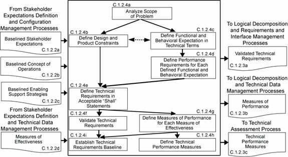
Figure C-2 - Technical Requirements Definition Process
a. The baseline set of validated technical requirements, including interface requirements (from Technical Requirements Definition and Configuration Management Processes).
b.The defined MOPs (from Technical Requirements Definition and Technical Data Management Processes).
a. Set of validated derived technical requirements, including interface requirements (to Design Solution Definition and Requirements and Interface Management Processes).
b.The set of logical decomposition models (to Design Solution Definition and Configuration Management Processes).
c. Logical decomposition work products (to Technical Data Management Processes).
a. Define one or more logical decomposition models based on the defined technical requirements to gain a more detailed understanding and definition of the design problem to be solved.
b.Allocate the technical requirements to the logical decomposition models to form a set of derived technical requirement statements that have the following characteristics:
1.Describe functional and performance, service and attribute, time, and data flow requirements, etc., as appropriate for the selected set of logical decomposition models.
2.Individually are complete sentences and are clear, correct, and feasible to satisfy; not stated as to how to be satisfied; implementable; only have one interpretation of meaning, one actor-verb-object expectation; and can be validated at the level of the system structure at which it is stated.
3.In pairs or as a set, have an absence of redundancy, are adequately related with respect to terms used, and are not in conflict with one another.
4.Form a set of detailed "design-to" requirements.
c. Resolve derived technical requirement conflicts.
d.Validate that the resulting set of derived technical requirements have: (1) bidirectional traceability with the set of validated technical requirements and (2) assumptions and decision rationale consistent with the source set of technical requirements.
e. Establish the derived technical requirements baseline.
A typical process flow diagram for logical decomposition is provided in Figure C-3 with inputs and their sources and the outputs and their destinations. The activities of the logical decomposition process are truncated to indicate the action and object of the action.
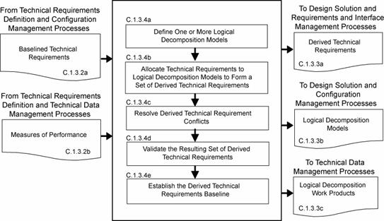
Figure C-3 - Logical Decomposition Process
a. A baselined set of logical decomposition models (from Logical Decomposition and Configuration Management Processes).
b.A baseline set of derived technical requirements including interface requirements (from Logical Decomposition and Configuration Management Processes).
The specified requirements that describe the system design solution definition for the products of the WBS model under development include:
a. A WBS model design solution definition set of requirements for the system (see WBS definition in Appendix A), including specification configuration documentation and external interface specification (to Requirements and Interface Management Process).
b.A baseline set of "make-to," "buy-to," "reuse-to," or set of "assemble and integrate-to" specified requirements (specifications and configuration documents) for the desired end product of the WBS model, including interface specifications (to Requirements and Interface Management Process).
c. The initial specifications for WBS model subsystems for flow down to the next applicable lower level WBS models, including interface specifications (to Stakeholder Expectations Definition, and Requirements and Interface Management Processes).
d.The requirements for enabling products that will be needed to provide life-cycle support to the end products, including interface requirements (to Stakeholder Expectations Definition Process for development of enabling products or to Product Implementation Process for acquisition of existing enabling products, and Requirements and Interface Management Processes).
e. A product verification plan that will be used to demonstrate that the product generated from the design solution definition conforms to the design solution definition specified requirements (to Product Verification Process).
f. A product validation plan that will be used to demonstrate that the product generated from the design solution definition conforms to its set of stakeholder expectations (to Product Validation Process).
g. Baseline operate-to and logistics procedures (to Technical Data Management Process).
For the WBS model in the system structure, the following activities are typically performed:
a. Define alternative solutions for the system end product being developed or improved that are consistent with derived technical requirements and non-allocated technical requirements, if any.
b.Analyze each alternative solution against defined criteria such as: satisfaction of external interface requirements; technology requirements; off-the-shelf availability of products; physical failure modes, effects and criticality; life-cycle cost and support considerations; capacity to evolve; make vs. buy; standardization of products; integration concerns; and context of use issues of operators considering tasks, location, workplace equipment, and ambient conditions.
c. Select the best solution alternative based on the analysis results of each alternative solution and technical decision analysis recommendations.
d.Generate the full design description of the selected alternative solution in a form appropriate to the product-line life-cycle phase, location of the WBS model in the system structure, and phase exit criteria to include: (1) system specification and external interface specifications; (2) end product specifications, configuration description documents, and interface specifications; (3) end product subsystem initial specifications, if subsystems are required; (4) requirements for associated supporting enabling products; (5) end product verification plan; (6) end product validation plan; and (7) applicable logistics and operate-to procedures.
e. Verify that the design solution definition: (1) is realizable within constraints imposed on the technical effort; (2) has specified requirements that are stated in acceptable statements and have bidirectional traceability with the derived technical requirements, technical requirements and stakeholder expectations; (3) has decisions and assumptions made in forming the solution consistent with its set of derived technical requirements, separately allocated technical requirements, and identified system product and service constraints.
f. Baseline the design solution definition specified requirements including the specifications and configuration descriptions.
g. Initiate development or acquisition of the life cycle supporting enabling products needed, as applicable, for research, development, fabrication, integration, test, deployment, operations, sustainment, and disposal.
h. Initiate development of the system products of the next lower level WBS model, if any.
A typical process flow diagram for design solution definition is provided in Figure C-4 with inputs and their sources and the outputs and their destinations. The activities of the design solution definition process are truncated to indicate the action and object of the action.
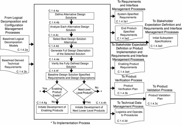
Figure C-4 - Design Solution Definition Process
There are five product realization processes. Four of the product realization processes are applied to each end product of a WBS model from the bottom to the top of the system structure: (1) either product implementation or product integration, (2) product verification, (3) product validation, and (4) product transition. (See Figure 3-2) The form of the end product realized will be dependent on the applicable product-line life-cycle phase, location within the system structure of the WBS model containing the end product, and the exit criteria of the phase. Typical early phase products are in the form of reports, models, simulations, mockups, prototypes, or demonstrators. Later phase product forms include the final mission products, including payloads and experiment equipment. For software products, the technical team should refer to NPR 7150.2 for software product realization requirements. The technical team should also ensure that the process implementations comply with NPR 7150.2, NASA Software Engineering Requirements for software aspects of the system. The product realization process descriptions that follow assume that each lowest level product goes through the sequencing shown in Figure C-5a. Exceptions will need to be planned according to what has and has not been already performed.
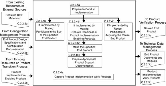
Figure C-5a -Sequencing of Design Realization Processes
a. Raw materials needed to make the end product (from existing resources or external sources).
b.End product design solution definition specified requirements (specifications) and configuration documentation for the end product of the applicable WBS model, including interface specifications, in the form appropriate to satisfying the product-line life-cycle phase exit criteria (from Configuration Management Process).
c. Product implementation enabling products (from existing resources or Product Transition Process for enabling product realization).
a. Made, bought, or reused end product in the form appropriate to the product-line life-cycle phase and to satisfy exit criteria (to Product Verification Process).
b.Documentation and manuals in a form appropriate for satisfying the life-cycle phase exit criteria, including "as-built" product descriptions and "operate-to" and maintenance manuals (to Technical Data Management Process).
c. Product implementation work products needed to provide reports, records, and non-deliverable outcomes of process activities (to Technical Data Management Process).
For the WBS model in the system structure, the following activities are typically performed:
a. Prepare to conduct product implementation to include (1) preparing a product implementation strategy and detailed planning and procedures; and (2) determining whether the product configuration documentation is adequately complete to conduct the type of product implementation as applicable for the product-line life-cycle phase, location of the product in the system structure, and phase exit criteria.
b.If the strategy is for buying an existing product, participate in the buy of the product including (1) review of the technical information made available by vendors; (2) assisting in the preparation of requests for acquiring the product from a vendor; (3) assisting in the inspection of the delivered product and the accompanying documentation; (4) determination of whether the vendor conducted product ,validation or if it will need to be done by a project technical team and (5) determination of the availability of enabling products to provide test, operations, and maintenance support and disposal services for the product.
c. If the strategy is to reuse a product that exists in the Government inventory, participate in the acquiring of the reuse product including: (1) review of the technical information made available for the specified product to be reused; (2) determination of supporting documentation and user manuals availability; (3) determination of avilability of enabling products to provide test, operations, and maintenance support and disposal services for the product; (5) assisting in the requests for acquiring the product from Government sources; and (4) assisting in the inspection of the delivered product and the accompanying documentation.
d.If the strategy is to make the product,
1.Evaluate the readiness of the product implementation enabling products to conduct the making of the product.
2.Make the specified product in accordance with the specified requirements, configuration documentation, and applicable standards.
3.Prepare appropriate product support documentation such as integration constraints and/or special procedures for performing product verification and product validation.
e. Capture work products and related information generated while performing the product implementation process activities.
C.2.1.5.1 Atypical process flow diagram for product implementation is provided in Figure C-5b with inputs and their sources and the outputs and their destinations. The activities of the product implementation process are truncated to indicate the action and object of the action.
C.2.1.5.2 The path that products from the three sources in Figure C-5b take with respect to product verification, product validation, and product transition vary based on:
a. Whether the products bought have been verified and/or validated by the vendor.
b.Whether reuse products that come from within the organization have been verified and/or validated.
c. Whether the customer for the product desires to do the product validation or have the developer perform the product validation.
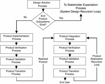
Figure C-5b - Product Implementation Process
a. Lower-level products to be assembled and integrated (from Product Transition Process).
b.End product design definition specified requirements (specifications) and configuration documentation for the applicable WBS model, including interface specifications, in the form appropriate to satisfying the product-line life-cycle phase exit criteria (from Configuration Management Process).
c. Product integration enabling products (from existing resources or Product Transition Process for enabling product realization).
a. Integrated product(s) in the form appropriate to the product-line life-cycle phase and to satisfy phase exit criteria (to Product Verification Process).
b.Documentation and manuals in a form appropriate for satisfying the life-cycle phase exit criteria, including "as-integrated" product descriptions and "operate-to" and maintenance manuals (to Technical Data Management Process).
c. Product integration work products needed to provide reports, records, and non-deliverable outcomes of process activities (to Technical Data Management Process).
For the WBS model in the system structure, the following activities are typically performed
a. Prepare to conduct product integration to include (1) preparing a product integration strategy, detailed planning for the integration, and integration sequences and procedures; and (2) determining whether the product configuration documentation is adequately complete to conduct the type of product integration applicable for the product-line life-cycle phase, location of the product in the system structure, and management phase exit criteria.
b. Obtain lower level products required to assemble and integrate into the desired product.
c. Confirm that the received products that are to be assembled and integrated have been validated to demonstrate that the individual products satisfy the agreed to set of stakeholder expectations, including interfaces requirements.
d.Prepare the integration environment in which assembly and integration will take place to include evaluating the readiness of the product integration enabling products and the assigned workforce.
e. Assemble and integrate the received products into the desired end product in accordance with the specified requirements, configuration documentation, interface requirements, applicable standards, and integration sequencing and procedures.
f. Prepare appropriate product support documentation such as special procedures for performing product verification and product validation.
g. Capture work products and related information generated while performing the product integration process activities.
A typical process flow diagram for product integration is provided in Figure C-6 with inputs and their sources and the outputs and their destinations. The activities of the product integration process are truncated to indicate the action and object of the action.

Figure C-6 - Product Integration Process
a. End product to be verified (from Product Implementation Process or Product Integration Process).
b. End product specification and configuration baselines, including interface specifications, to which the product being verified was generated (from Technical Data Management Process).
c. Product verification plan (from Design Solution Definition Process and Technical Planning Process)
d.Product verification enabling products (from existing resources or Product Transition Process for enabling product realization).
a. A verified end product (to Product Validation Process).
b. Product verification results (to Technical Assessment Process).
c. Completed verification report to include for each specified requirement: (1) the source paragraph references from the baseline documents for derived technical requirements, technical requirements and stakeholder expectations; (2) bidirectional traceability among these sources; (3) verification type(s) to be used in performing verification of the specified requirement; (4) reference to any special equipment, conditions, or procedures for performing the verification; (5) results of verification conducted; (6) variations, anomalies, or out-of-compliance results; (7) corrective actions taken; and (8) results of corrective actions (to Technical Data Management Process).
d. Product verification work products needed to provide reports, records, and non-deliverable outcomes of process activities (to Technical Data Management Process).
For the WBS model in the system structure, the following activities are typically performed:
a. Prepare to conduct product verification to include as applicable to the product-line life-cycle phase and WBS model location in the system structure: (1) reviewing the product verification plan for specific procedures, constraints, conditions under which verification will take place, pre and post verification actions, and criteria for determining the success or failure of verification methods and procedures; (2) arranging the needed product verification enabling products and support resources; (3) obtaining the end product to be verified; (4) obtaining the specification and configuration baseline against which the verification is to be made; and (5) establishing and checking the verification environment to ensure readiness for performing the verification.
b.Perform the product verification in accordance with the product verification plan and defined procedures to collect data on each specified requirement with specific attention given to MOPs.
c. Analyze the outcomes of the product verification to include identification of verification anomalies, establishing recommended corrective actions, and/or establishing conformance to each specified requirement under controlled conditions.
d.Prepare a product verification report providing the evidence of product conformance with the applicable design solution definition specified requirements baseline to which the product was generated including bidirectional requirements traceability and corrective actions taken to correct anomalies of verification results.
e. Capture the work products from the product verification.
A typical process flow diagram for product verification is provided in Figure C-7 with inputs and their sources and the outputs and their destinations. The activities of the product verification process are truncated to indicate the action and object of the action.

Figure C-7 - Product Verification Process
a. End product to be validated (from Product Verification Process).
b.Stakeholder requirements baseline (from Configuration Management Process).
c. Product validation plan (from Design Solution Definition Process and Technical Planning Process)
d.Product validation enabling products (from existing resources or Product Transition Process for enabling product realization).
a. A validated end product (to Transition Process).
b.Product validation results (to Technical Assessment Process).
c. Completed validation report to include for each stakeholder expectation or subset of stakeholder expectations involved with the validation, for example: (1) the source requirement paragraph reference from the stakeholder expectations baseline; (2) validation type(s) to be used in establishing compliance with selected set of stakeholder expectations and match with each source expectation referenced; (3) identification of any special equipment, conditions or procedures for performing the validation that includes referenced expectation; (4) results of validation conducted with respect to the referenced expectation; (5) deficiency findings (variations, anomalies or out-of-compliance results); (6) corrective actions taken; and (7) results of corrective actions (to Technical Data Management Process).
d.Product validation work products needed to provide reports, records, and non-deliverable outcomes of process activities (to Technical Data Management Process).
For the WBS model in the system structure, the following activities are typically performed:
a. Prepare to conduct product validation to include as applicable to the product-line life-cycle phase and product location in the system structure: (1) reviewing the product validation plan for specific procedures, constraints, conditions under which validation will take place, pre and post validation actions, and criteria for determining the success or failure of validation methods and procedures; (2) arranging the needed product validation enabling products and support resources; (3) obtaining the end product to be validated; (4) obtaining the stakeholder expectations baseline against which the validation is to be made; and (5) establishing and checking out the validation environment to ensure readiness for performing the validation.
b.Perform the product validation in accordance with the product validation plan and defined procedures to collect data on performance of the product against stakeholder expectations with specific attention given to MOEs.
c. Analyze the outcomes of the product validation to include identification of validation anomalies, establishing recommended corrective actions, and/or establishing conformance to stakeholder expectations under operational conditions (actual, analyzed or simulated).
d.A product validation report providing the evidence of product conformance with the stakeholder expectations baseline including corrective actions taken to correct anomalies of validation results
e. Capture the work products from the product validation.
A typical process flow diagram for product validation is provided in Figure C-8 with inputs and their sources and the outputs and their destinations. The activities of the product validation process are truncated to indicate the action and object of the action.
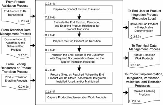
Figure C-8 - Product Validation Process
a. End product or products to be transitioned (from Product Validation Process).
b.Documentation including manuals, procedures and processes that are to accompany the end product (from Technical Data Management Process).
c. Product transition enabling products to include packaging materials, containers, handling equipment, and storage, receiving and shipping facilities (from existing resources or Product Transition Process for enabling product realization).
a. Delivered end product with applicable documentation including manuals, procedures and processes in a form consistent with the product-line life-cycle phase and location of the product in the system structure (to end user or Product Integration Process - recursive loop).
b.Product transition work products needed to provide reports, records, and non-deliverable outcomes of process activities (to Technical Data Management Process).
c. Realized enabling products from existing enabling products and services or from applying the common technical processes to develop and realize (to Product Implementation, Integration, Verification, Validation and Transition Processes, as appropriate)
For the WBS model in the system structure, the following activities are typically performed:
a. Prepare to conduct product transition to include (1) preparing a product implementation strategy to establish the type of product transition to be made (to the next higher level customer for product integration or to an end user); and (2) reviewing related end product stakeholder expectations and design solution definition specified requirements to identify special transition procedures and enabling product needs for the type of product transition, if any, for packaging, storage, handling, shipping/transporting, site preparation, installation, and/or sustainment.
b.Evaluate the end product, personnel, and enabling product readiness for product transition including: (1) availability and appropriateness of the documentation that will be packaged and shipped with the end product; (2) adequacy of procedures for conducting product transition; (3) availability and skills of personnel to conduct product transition; and (4) availability of packaging materials/containers, handling equipment, storage facilities, and shipping/transporter services.
c. Prepare the end product for transition to include the packaging and moving the product to the shipping/transporting location and any intermediate storage.
d.Transition the end product with required documentation to the customer based on the type of transition required, e.g., to the next higher level WBS model for product integration or to the end user.
e. Prepare sites, as required, where the end product will be stored, assembled, integrated, installed, used, and/or maintained, as appropriate for the life-cycle phase, position of the end product in the system structure, and customer agreement.
f.Capture work products from product transition process activities.
A typical process flow diagram for product transition is provided in Figure C-9 with inputs and their sources and the outputs and their destinations. The activities of the product transition process are truncated to indicate the action and object of the action.
![]()
Figure C-9 - Product Transition Process
There are eight technical management processes-Planning, Requirements Management, Interface Management, Risk Management, Configuration Management, Technical Data Management, Assessment, and Decision Analysis. (See Figure 3-2.)These technical management processes are intended to supplement the management requirements defined in NPR 7120.5. NPR 7120.5 provides program and project managers with the technical activities that they are required to be cognizant of and are responsible for. On the other hand, the technical management process in this SE NPR: (1) provide the technical team their requirements for planning, monitoring and controlling the technical effort as well as the technical decision analysis requirements for performing tradeoff and effectiveness analyses to support decisionmaking throughout the technical effort; (2) focus on (a) completion of technical process planning (preparation of the SEMP and other technical plans), (b) technical progress assessment (using technical measures and conducting technical reviews to assess progress against the SEMP and defined technical requirements), and (c) control of product requirements, product interfaces, technical risks, configurations, technical data and include ensuring that common technical process implementations comply with NPR 7150.2 software product realization requirements for software aspects of the system. Documentation produced through each technical management process should be managed and dispositioned as Federal records.
a. Project technical effort requirements and project resource constraints (from the project).
b.Agreements, capability needs and applicable product-line life-cycle phase(s) (from the project).
c. Applicable policies, procedures, standards, and organizational processes (from the project).
d.Prior product-line life-cycle phase or baseline plans (from Technical Data Management Process).
e. Re-planning needs (from Technical Assessment and Technical Risk Management Processes).
a. Technical work cost estimates, schedules, and resource needs, e.g., funds, workforce, facilities, and equipment (to project).
b.Product and process measures needed to assess progress of the technical effort and the effectiveness of processes (to Technical Assessment Process).
c. The SEMP and other technical plans that support implementation of the technical effort (to all processes; applicable plans to Technical Processes).
d.Technical work directives, e.g., work packages or task orders with work authorization (to applicable technical teams).
e. Technical planning work products needed to provide reports, records, and nondeliverable outcomes of process activities (to Technical Data Management Process).
For the WBS model in the system structure, the following activities are typically performed:
a. Prepare to conduct technical planning to include:
1.Preparing or updating a planning strategy for each of the common technical processes of this SE NPR.
2.Determining:
a) deliverable work products from technical efforts.
b) technical reporting requirements.
c) other technical information needs for reviews or satisfying product-line life-cycle management phase entry or exit criteria.
d) product and process measures to be used in measuring technical performance, cost, and schedule progress.
e) key or critical technical events with entry and success criteria.
f) data management approach for data collection and storage and how measurement data will be analyzed, reported, and dispositioned as Federal records.
g) technical risks that need to be addressed in the planning effort.
h) tools and engineering methods to be employed in the technical effort.
i) approach to acquiring and maintaining the technical expertise needed (training and skills development plan).
b.Define the technical work to be done to include associated technical, support, and management tasks needed to generate the deliverable products and satisfy entry and success criteria of key technical events and the applicable product-line life-cycle management phase.
c. Schedule, organize, and cost the technical effort.
d.Prepare the SEMP and other technical plans needed to support the technical effort and perform the technical processes.
e. Obtain stakeholder commitments to the technical plans.
f. Issue authorized technical work directives to implement the technical work.
g. Capture work products from technical planning activities
A typical process flow diagram for technical planning is provided in Figure C-10 with inputs and their sources and the outputs and their destin,ations. The activities of the technical planning process are truncated to indicate the action and object of the action.

Figure C-10 - Technical Planning Process
a. Expectations and requirements to be managed (from System Design Processes).
b. Requirement change requests (the project and Technical Assessment Process).
c. TPM estimation/evaluation results (from Technical Assessment Process)
d.Product verification and product validation results (from Product Verification and Validation Processes)
a. Requirement documents (to Configuration Management Process).
b.Approved changes to requirement baselines (to Configuration Management Process).
c. Requirements management work products needed to provide reports, records and non-deliverable outcomes of process activities (to Technical Data Management Process).
For the WBS model in the system structure, the following activities are typically performed:
a. Prepare to conduct requirements management to include:
1. Preparing or updating a strategy and procedures for:
a) establishing that expectation and requirement statements, singularly and as a whole, are prepared in accordance with established formats and rules.
b) identifying expectations and requirements to be managed, expectation and requirement sources, allocation and traceability of requirements, and linking product expectations and requirements with costs, weight, and power allocations as applicable
c) formal initiation, assessment, review, approval and disposition of engineering change proposals and changes to expectation and requirements baseline.
2.Selecting or updating an appropriate requirements management tool.
3.Training technical team members in the established requirements management procedures and in the use of the selected/updated requirements management tool.
b.Conduct requirements management to include: (1) capturing, storing and documenting the expectations and requirements; (2) establishing that expectation and requirement statements are compliant with format and other established rules; (3) confirming that each established requirements baseline has been validated; and (4) identifying and analyzing out-of-tolerance system-critical technical parameters and unacceptable validation and verification results and proposing requirement appropriate changes to correct out-of-tolerance requirements.
c. Conduct expectation and requirements traceability to include: (1) tracking expectations and requirements between baselines, especially MOEs, MOPs, and TPMs, and (2) establishing and maintaining appropriate requirements compliance matrixes that contain the requirements, bidirectional traceability, compliance status, and any actions to complete compliance.
d.Manage expectation and requirement changes to include: (1) reviewing engineering change proposals (ECPs) to determine any changes to established requirement baselines, (2) implementing formal change procedures for proposed and identified expectation or requirement changes, and (3) disseminating the approved change information.
e. Capture work products from requirements management process activities to include maintaining and reporting information on the rationale for and disposition and implementation of change actions, current requirement compliance status, and expectation and requirement baselines.
A typical process flow diagram for requirements management is provided in Figure C-11 with inputs and their sources and the outputs and their destinations. The activities of the requirements management process are truncated to indicate the action and object of the action.
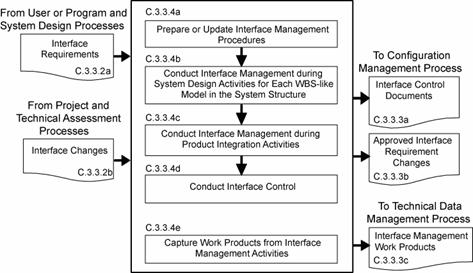
Figure C-11 - Requirements Management Process
a. Internal and external functional and physical interface requirements for the products of a WBS model (from user or program and System Design Processes).
b.Interface change requests (from project, and Technical Assessment Processes).
a. Interface Control Documents (to Configuration Management Processes).
b.Approved interface requirement changes (to Configuration Management Process)
c. Interface management work products needed to provide reports, records, and non-deliverable outcomes of process activities (to Technical Data Management Process)
For the WBS model in the system structure, the following activities are typically performed:
a. Prepare or update interface management procedures for (1) establishing interface management responsibilities for those interfaces that are part of agreement boundaries, (2) maintaining and controlling identified internal and external physical and functional interfaces, (3) preparing and maintaining appropriate physical and functional interface specifications or interface control documents and drawings to describe and control interfaces external to the system end product, (4) identifying interfaces between system products (including humans) and among configuration management items, (5) establishing and implementing formal change procedures for interface evolution, (6) disseminating the needed interface information for integration into technical effort activities and for external interface control, and (7) training technical teams and other applicable support and management personnel in the established interface management procedures.
b.Conduct interface management during system design activities for each WBS model in the system structure to include: (1) integrating the interface management activities with requirements management activities; (2) analyzing the concept of operations to identify critical interfaces not included in the stakeholder set of expectations; (3) documenting interfaces both external and internal to each WBS model as the development of the system structure emerges and interfaces are added and existing interfaces are changed; (4) documenting origin, destination, stimulus, and special characteristics of interfaces; (5) maintaining the design solution definition for internal horizontal and vertical interfaces between WBS models in the system structure; (6) maintaining horizontal traceability of interface requirements across interfaces and capturing status in the established requirements compliance matrix; and (7) confirming that each interface control document or drawing that is established has been validated with parties on both sides of the interface.
c. Conduct interface management during product integration activities to include: (1) reviewing product integration procedures to ensure that interfaces are marked to ensure easy and correct assembly/connection with other products, (2) identifying product integration planning to identify interface discrepancies, if any, and report to the proper technical team or technical manager, (3) confirming that a pre-check is completed on all physical interfaces before connecting products together, (4) evaluating assembled products for interface compatibility, (5) confirming that product verification and product validation plans/procedures include confirming internal and external interfaces, and (6) preparing an interface evaluation report upon completion of integration and product verification and product validation.
d.Conduct interface control to include: (1) managing interface changes within the system structure, (2) identifying and tracking proposed and directed changes to interface specifications and interface control documents and drawings, (3) confirming that the vertical and horizontal interface issues are analyzed and resolved when a change affects products on both sides of the interface, (4) controlling traceability of interface changes including source of the change, processing methods and approvals, and (5) disseminating the approved interface change information for integration into technical efforts at every level of the project.
e. Capture work products from interface management activities.
A typical process flow diagram for interface management is provided in Figure C-12 with inputs and their sources and the outputs and their destinations. The activities of the interface management process are truncated to indicate the action and object of the action.
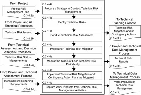
Figure C-12 - Interface Management Process
a. Project Risk Management Plan (from project)
b.Technical risk issues (from project and other common technical processes).
c. Technical risk status measurements (from Technical Assessment and Decision Analysis Processes).
d.Technical risk reporting requirements (from project and Technical Planning Process).
a. Technical risk mitigation and/or contingency actions (to Technical Planning Process for re-planning and/or re-direction).
b.Technical risk reports (to project and Technical Data Management Process).
c. Work products from technical risk management activities (to Technical Data Management Process).
For the WBS model in the system structure, the following activities are typically performed; (NPR 8000.4, Risk Management Procedural Requirements, is to be used as a source document for defining this process and implementing procedures.)
a. Prepare a strategy to conduct technical risk management to include: (1) documenting how the project risk management plan will be implemented in the technical effort; (2) planning identification of technical risk sources and categories; (3) identification of potential technical risks; (4) characterizing and prioritizing technical risks; (5) planning informed technical management (mitigation) actions should the risk event occur; (6) tracking technical risk status against established trigger; (7) resolving technical risk by taking planned action if established trigger is tripped; and (8) communicating technical risk status and mitigation actions taken, when appropriate.
b.Identify technical risks to include: (1) identifying sources of risk issues related to the technical effort; (2) anticipate what can go wrong in each of the source areas to create technical risk issues; (3) analyzing identified technical risks for cause and importance; (4) preparing clear, understandable, and standard form risk statements; and (5) coordinating with relevant stakeholders associated with each identified technical risk.
c. Conduct technical risk assessment to include: (1) categorizing the severity of consequences for each identified technical risk in terms of performance, cost, and schedule impacts to the technical effort and project; (2) analyze the likelihood and uncertainties of events associated with each technical risk and quantify (for example by probabilities) or qualify (for example by high, moderate, or low) the probability of occurrence in accordance with project risk management plan rules; and (3) prioritize risks for mitigation.
d.Prepare for technical risk mitigation to include: (1) selecting risks for risk mitigation and monitoring, (2) selecting an appropriate risk handling approach, (3) establishing the risk level or threshold when risk occurrence becomes unacceptable and triggers execution of a risk mitigation action plan, (4) selecting contingency actions and triggers should risk mitigation not work to prevent a problem occurrence, (5) preparing risk mitigation and contingency action plans with identification of responsibilities and authorities.
e. Monitor the status of each technical risk periodically to include: (1) tracking risk status to determine whether conditions or situations have changed so that a risk monitoring is no longer needed or new risks have been discovered, (2) comparing risk status and risk thresholds, (3) reporting risk status to decision authorities when a threshold has been triggered and an action plan implemented, (4) preparing technical risk status reports as required by the project risk management plan, (5) communicating risk status during technical reviews in the form specified by the project risk management plan.
f. Implement technical risk mitigation and contingency action plans when the applicable thresholds have been triggered to include: (1) monitoring the results of the action plan implemented, (2) modifying the action plan as appropriate to the results of the actions, (3) continuing actions until the residual risk and/or consequences impacts are acceptable or become a problem to be solved, (4) communicate to the project when risks are beyond the scope of the technical effort to control, will affect a product higher in the system structure, or represent a significant threat to the technical effort or project success, (5) preparing action plan effectiveness reports as required by the project risk management plan, (6) communicating action plan effectiveness during technical reviews in the form specified by the project risk management plan.
g. Capture work products from technical risk management activities.
A typical process flow diagram for technical risk management is provided in Figure C-13 with inputs and their sources and the outputs and their destinations. The activities of the technical risk management process are truncated to indicate the action and object of the action.
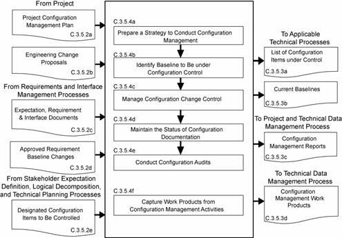
Figure C-13 - Technical Risk Management Process
a. Project configuration management plan, if any (from project).
b. ECPs (from contractors, if any, and technical teams).
c. Expectations and requirement outputs to include stakeholder expectations, technical requirements, derived technical requirements, system and end product specifications, requirement documents, and interface control documents/drawings (from Requirements and Interface Management Processes).
d.Approved requirement baseline changes, including interface requirement changes (from Requirements Management and Interface Management Processes).
e. Concepts of operations, enabling product strategies, logical decomposition models, SEMP, technical plans, and other configuration items identified in the list of CIs to be controlled (from Stakeholder Expectation Definition, Logical Decomposition, Technical Planning, and other technical processes as appropriate).
a. List of configuration items to be placed under control (to applicable technical processes).
b.Current baselines (to Technical Requirements Definition, Logical Decomposition, Design Solution Definition, and Product Implementation, Integration, Verification, and Validation Processes.)
c. Configuration management reports (to project and Technical Data Management Process).
d.Work products from configuration management activities (to Technical Data Management Process).
For the WBS model in the system structure, the following activities are typically performed:
a. Prepare a strategy to conduct configuration management for the system products and designated work products to include: (1) documenting how the project configuration management plan, if any, will be implemented; (2) identifying configuration items to be put under configuration control; (3) identifying schema of identifiers to accurately describe a configuration item and its revisions or versions; (4) controlling changes to configuration items; (5) maintaining and reporting disposition and implementation of change actions to appropriate stakeholders including technical teams within the project; (6) ensuring that products are in compliance with specifications and configuration documentation during reviews and audits; (7) providing the appropriate reference configuration at the start of each product-line life-cycle phase; (8) obtaining appropriate tools for configuration management; and (9) training appropriate technical team members and other technical support and management personnel in the established configuration management strategy and any configuration management procedures and tools.
b. Identify baselines to be under configuration control to include: (1) listing of the configuration items to control; (2) providing each configuration item with a unique identifier; (3) identifying acceptance requirements for each baseline identified for control; (4) identifying the owner of each configuration item; and (5) establishing a baseline configuration for each configuration item.
c. Manage configuration change control to include: (1) establishing change criteria, procedures, and responsibilities; (2) receive, record, and evaluate change requests; (3) tracking change requests to closure; (4) obtaining appropriate approvals before implementing a change; (5) incorporating approved changes in appropriate configuration items; (6) releasing changed configuration items for use; and (7) monitoring implementation to determine whether changes resulted in unintended effects (e.g., have not compromised safety or security of baseline product).
d.Maintain the status of configuration documentation to include: (1) maintaining configuration item description records and records that verify readiness of configuration items for testing, delivery, or other related technical efforts; (2) maintaining change requests, disposition action taken, and history of change status; (3) maintaining differences between successive baselines; and (4) controlling access to and release of configuration baselines.
e. Conduct configuration audits to include: (1) auditing baselines under control to confirm that the actual work product configuration matches the documented configuration, the configuration is in conformance with product requirements, and records of all change actions are complete and up to date; (2) identifying risks to the technical effort based on incorrect documentation, implementation, or tracking of changes; (3) assessing the integrity of the baselines; (4) confirming the completeness and correctness of the content of configuration items with applicable requirements; (5) confirming compliance of configuration items with applicable configuration management standards and procedures; and (6) tracking action items to correct anomalies from audit to closure.
f. Capture work products from configuration management activities to include a list of identified configuration items; description of configuration items placed under control; change requests and disposition of the request and rationale for the disposition; documented changes with reason for change and change action; archive of old baselines; and required reports on configuration management outcomes.
A typical process flow diagram for configuration management is provided in Figure C-14 with inputs and their sources and the outputs and their destinations. The activities of the configuration management process are truncated to indicate the action and object of the action.
|
|
|
|
|
|
Figure C-14 - Configuration Management Process
a. Technical data and work products to be managed (from all technical processes and contractors).
b.Requests for technical data (from all technical processes and project).
a. Form of technical data products (to all technical processes and contractors).
b.Technical data electronic exchange formats (to all technical processes and contractors).
c. Delivered technical data (to project and all technical processes).
For the WBS model in the system structure, the following activities are typically performed:
a. Prepare a strategy for the conduct of technical data management to include: (1) determining required data content and form and electronic data exchange interfaces in accordance with international standards or agreements; (2) establishing a framework for technical data flow within the project technical processes and to/from contractors; (3) designating technical data management responsibilities and authorities regarding origination, generation, capture, archiving, security, privacy and disposal of technical data work products; (4) establishing the rights, obligations, and commitments regarding the retention of, transmission of, and access to technical data items; (5) establishing relevant data storage, transformation, transmission, and presentation standards and conventions to be used, project or program policy, and agreements or legislative constraints; (6) describing the methods, tools, and metrics used during the technical effort and for technical data management; and (7) training appropriate technical team members and support and management personnel in the established technical data management strategy and related procedures and tools.
b.Collect and store required technical data to include: (1) identifying existing sources of technical data that are designated as outputs of the common technical processes; (2) collecting and storing technical data in accordance with the technical data management strategy and procedures; (3) recording and distributing lessons learned; (4) performing technical data integrity checks on collected data to confirm compliance with content and format requirements and identifying errors in specifying or recording data; and (5) prioritizing, reviewing, and updating technical data collection and storage procedures.
c. Maintain stored technical data to include: (1) managing the databases to maintain proper quality and integrity of the collected and stored technical data and to confirm that the technical data is secure and is available to those with authority to have access; (2) performing technical data maintenance as required; (3) preventing the stored data from being used or accessed inappropriately; (4) maintaining the stored technical data in a manner that protects it against foreseeable hazards such as fire, flood, earthquake, and riots; and (5) maintaining periodic back-ups of each technical database.
d.Provide technical data to authorized parties to include: (1) maintaining an information library or reference index to provide data available and access instructions; (2) receiving and evaluating requests for technical data and delivery instructions; (3) confirming that required and requested technical data is appropriately distributed to satisfy the needs of the requesting party and in accordance with established procedures, directives, and agreements; (4) confirming that electronic access rules are followed before allowing access to the database and before any data is electronically released/transferred to the requester; and (5) provide proof of correctness, reliability, and security of technical data provided to internal and external recipients.
A typical process flow diagram for technical data management is provided in Figure C-15 with inputs and their sources and the outputs and their destinations. The activities of the technical data management process are truncated to indicate the action and object of the action.
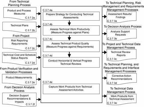
Figure C-15 - Technical Data Management Process
a. Process and product measures (from Technical Planning Process).
b.Technical plans including the SEMP (from Technical Planning Process).
c. Risk reporting requirements during technical reviews (from project).
d.Technical cost and schedule status reports (from project).
e. Product measurements (from Product Verification and Product Validation Processes).
f. Decision support recommendations and impacts (from Decision Analysis Process).
a. Assessment results and findings including technical performance measurement estimates of measures (to Technical Planning, Technical Risk Management and Requirements Management Processes).
b.Analysis support requests (to Decision Analysis Process).
c. Technical review reports (to project and Technical Data Management Process).
d.Corrective action and requirement change recommendations including corrective actions to correct out-of-tolerance TPMs (to Technical Planning, Requirements Management, and Interface Management Processes).
e. Work products from technical assessment activities (to Technical Data Management Process).
For the WBS model in the system structure, the following activities are typically performed:
a. Prepare a strategy for conducting technical assessments to include: (1) identifying the plans against which progress and achievements of the technical effort are to be assessed; (2) establishing procedures for obtaining cost expenditures against work planned and task completions against schedule; (3) identifying and obtaining technical requirements against which product development progress and achievement will be assessed and establishing the procedures for conducting the assessments; (4) establishing events when TPMs, estimation or measurement techniques, and rules for taking action when out-of-tolerance conditions exist will be assessed; (5) identifying and planning for phase-to-phase technical reviews and WBS model-to-model vertical progress reviews, as well as establishing review entry and success criteria, review board members, and close out procedures; (6) establishing which technical effort work products will undergo peer review, the team members who will perform the peer reviews, and reporting requirements; and (7) training team members, support staff, and managers involved in conducting technical assessment activities.
b.Assess technical work productivity (progress and achievement against plans) to include: (1) identifying, collecting, and analyzing process measures (e.g., earned value measurements for measuring progress against planned cost, schedule, resource use, and technical effort tasks) and identifying and reporting cost-effective changes to correct variances; (2) monitoring stakeholder involvement according to the SEMP; and (3) monitoring technical data management against plans.
c. Assess product quality (progress and achievements against technical requirements) to include: (1) identifying, collecting, and analyzing the degree of technical requirement and TPM satisfaction; (2) assessing the maturity of the WBS model products and services as applicable to the applicable product-line life-cycle phases; (3) determining any variances from expected values of product performance and identifying and defining cost-effective changes to correct variances.
d.Conduct technical reviews to include: (1) identifying the type of technical reviews and each review's purpose and objectives (see Chapter 5 for specific technical reviews that apply); (2) determining progress toward satisfying entry criteria; (3) establishing the makeup of the review team; (4) preparing the review presentation materials; and (5) identifying and resolving action items resulting from the review.
e. Capture work products from the conduct of technical assessment activities to include: (1) identifying variances resulting from technical assessments; (2) identifying and reporting changes to correct variances; (3) recording methods used in doing assessment activities; (4) documenting assumptions made in arriving at the process and product measure outcomes; and (5) reporting corrective action recommendations.
A typical process flow diagram for technical assessment is provided in Figure C-16 with inputs and their sources and the outputs and their destinations. The activities of the technical assessment process are truncated to indicate the action and object of the action.
|
|
|
|
|
|
Figure C-16 - Technical Assessment Process
a. Decision need, alternatives, issues, or problems and supporting data (from all Technical Processes).
b.Analysis support requests (from Technical Assessment Process).
a. Alternative selection recommendations and impacts (to all Technical Processes)
b.Decision support recommendations and impacts (to Technical Assessment Process)
c. Work products of decision analysis activities (to Technical Data Management Process).
For the WBS model in the system structure, the following activities are typically performed:
a. Establish guidelines to determine which technical issues are subject to a formal analysis/evaluation process to include: (1) when to use a formal decisionmaking procedure, for example, as a result of an effectiveness assessment, a technical trade off, a problem needing to be solved, action needed as a response to risk exceeding the acceptable threshold, verification or validation failure, make-buy choice, evaluating a solution alternative, or resolving a requirements conflict; (2) what needs to be documented; (3) who will be the decision makers and their responsibilities and decision authorities; (4) how decisions will be handled that do not require a formal evaluation procedure.
b. Define the criteria for evaluating alternative solutions to include: (1) the types of criteria to consider including the following: technology limitations, environmental impact, safety, risks, total ownership and life-cycle costs, and schedule impact; (2) the acceptable range and scale of the criteria; and (3) the rank of each criterion by its importance.
c. Identify alternative solutions to address decision issues to include alternatives for consideration in addition to those that may be provided with the issue.
d.Select evaluation methods and tools/techniques based on the purpose for analyzing a decision and on the availability of the information used to support the method and/or tool.
e. Evaluate alternative solutions with the established criteria and selected methods to include: (1) evaluation of assumptions related to evaluation criteria and of the evidence that supports the assumptions; and (2) evaluation of whether uncertainty in the values for alternative solutions affects the evaluation.
f. Select recommended solutions from the alternatives based on the evaluation criteria to include documenting the information that justifies the recommendations and gives the impacts of taking the recommended course of action.
g. Report the analysis/evaluation results/findings with recommendations, impacts, and corrective actions.
h. Capture work products from decision analysis activities to include: (1) decision analysis guideline generated and strategy and procedures used; (2) analysis/ evaluation approach, criteria, and methods and tools used; (3) analysis/evaluation results, assumptions made in arriving at recommendations, uncertainties, and sensitivities of the recommended actions or corrective actions; and (4) lessons learned and recommendations for improving future decision analyses.
A typical process flow diagram for technical decision analyses is provided in Figure C-17 with inputs and their sources and the outputs and their destinations. The activities of the decision analysis process are truncated to indicate the action and object of the action.
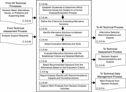
Figure C-17 - Decision Analysis Process
The purpose of this appendix is to provide an annotated outline for a SEMP for use by NASA in planning the technical effort required for in-house and contracted projects. The SEMP is the technical planning document for systems engineering. The SEMP is designed to be a single, integrated technical planning document for the conduct and management of the required technical effort that is the responsibility of an in-house NASA project. The resulting technical plan is to represent the agreed-to and approved tailoring of the requirements of the SE NPR to satisfy project technical requirements. The plan is to be used by the technical team responsible for generating technical work products to integrate and manage the full spectrum of technical activities required to engineer the system covered by the SEMP. The SEMP needs to be coordinated with the project plan for integration of the technical planning and modifications related to the allocated resources, including cost, schedule, personnel, facilities, and deliverables required. The plan will also be used to evaluate the team's technical approach, to make technical risk assessments, and to measure progress.
Terminology is a key factor in ensuring a common understanding of the technical effort to be accomplished. Terms used in the SEMP need to have the same meaning as the terms used in the SE NPR.
The SEMP outline in this appendix is to be used in preparing a project SEMP. For a small project the material in the SEMP can be placed in the project plan's technical summary and this annotated outline used as a topic guide.
D.3.2.1 SEMP tailoring is to be consistent with the SE NPR tailoring requirements and guidelines. (See Appendix F.) The SEMP is to include documentation of any tailoring to the SE NPR requirements and SEMP sections or subsections. Tailoring is an adaptation of a process or approach to meet a requirement, whereas a waiver is a documented agreement intentionally releasing a program or project from meeting a requirement. Tailored requirements will be documented directly following the heading of each affected SEMP section or subsection. Tailored SE NPR requirements that are not directly related to a SEMP section or subsection will be documented in the waiver section.
For projects with significant portions of the engineering work contracted out, the SEMP should scope and plan the NASA project's implementation of the common technical processes before, during, and at the completion of the contracted effort. This should include planning the technical team's involvement in RFP preparation, in source selection activities, and in acceptance of deliverables. The interface activities with the contractor, including NASA technical team involvement with and monitoring of contracted work, should be a focus of the SEMP.
The SEMP contains the following sections, unless they have been tailored out. Cross references to detailed information in related technical plans are included in each pertinent SEMP section.
a. Purpose and Scope.
b. Applicable Documents and Designated Governing Authority.
c. Technical Summary.
d. Technical Effort Integration.
e. Common Technical Processes Implementation.
f. Technology Insertion.
g. Additional SE Functions and Activities.
h. Integration with the Project Plan Resource Allocation.
i. Waivers.
j. Appendices.
This section provides a brief description of the purpose, scope, and content of the SEMP. The scope encompasses the SE technical effort required to generate the work products necessary to meet the exit criteria for the product-line life-cycle phases.
This section of the SEMP lists the documents applicable to SEMP implementation and describes major standards and procedures that the technical effort needs to follow. Specific implementation of standardization tasking is incorporated into pertinent sections of the SEMP.
This section contains an executive summary describing the problem to be solved by this technical effort.
This subsection contains a definition of the purpose of the system being developed and a brief description of the purpose of the products of the WBS models of the system structure for which this SEMP applies. Each WBS model includes the system end products and their subsystems and the supporting or enabling products and any other work products (plans, baselines) required for the development of the system. The description should include any interfacing systems and system products, including humans, with which the WBS model system products will interact physically, functionally, or electronically.
This subsection contains an explanation of how the WBS models will be developed; how the resulting WBS model will be integrated into the project WBS; and how the overall system structure will be developed. This subsection contains a description of the relationship of the specification tree and the drawing tree with the products of the system structure and how the relationship and interfaces of the system end products and their life-cycle-enabling products will be managed throughout the planned technical effort.
This subsection contains an explanation of how the product will be integrated and will describe clear organizational responsibilities and interdependencies whether the organizations are geographically dispersed or managed across Centers.
This section contains the product-line life-cycle model constraints (e.g., NPR 7120.5) that affect the planning and implementation of the common technical processes to be applied in performing the technical effort. The constraints provide a linkage of the technical effort with the applicable product-line life-cycle phases covered by the SEMP including, as applicable, milestone decision gates, major technical reviews, key intermediate events leading to project completion, life-cycle phase, event entry and exit criteria, and major baseline and other work products to be delivered to the sponsor or customer of the technical effort.
This subsection contains a description of the boundary of the general problem to be solved by the technical effort. Specifically, it identifies what can be controlled by the technical team (inside the boundary) and what influences the technical effort and is influenced by the technical effort but not controlled by the technical team (outside the boundary). Specific attention should be given to physical, functional, and electronic interfaces across the boundary.
This subsection contains cross references to appropriate nontechnical plans that interface with the technical effort. This section contains a summary description of how the technical activities covered in other plans are accomplished as fully integrated parts of the technical effort.
This section contains a description of how the various inputs to the technical effort will be integrated into a coordinated effort that meets cost, schedule, and performance objectives.
This subsection contains a description of the organizing structure for the technical teams assigned to this technical effort and includes how the teams will be staffed and managed, including (a) what organization/panel will serve as the DGA for this project and, therefore, will have final signature authority for this SEMP; (b) how multidisciplinary teamwork will be achieved; (c) identification and definition of roles, responsibilities, and authorities required to perform the activities of each planned common technical process; (d) planned technical staffing by discipline and expertise level, with human resource loading; (e) required technical staff training; and (f) assignment of roles, responsibilities, and authorities to appropriate project stakeholders or technical teams to assure planned activities are accomplished.
This subsection contains a description of how the technical effort of in-house and external contractors is to be integrated with the NASA technical team efforts. This includes establishing technical agreements, monitoring contractor progress against the agreement, handling technical work or product requirements change requests, and acceptance of deliverables. The section will specifically address how interfaces between the NASA technical team and the contractor will be implemented for each of the 17 common technical processes. For example, it addresses how the NASA technical team will be involved with reviewing or controlling contractor-generated design solution definition documentation or how the technical team will be involved with product verification and product validation activities.
This subsection contains a description of the methods (such as integrated computer-aided tool sets, integrated work product databases, and technical management information systems) that will be used to support technical effort integration.
Each of the 17 common technical processes will have a separate subsection that contains the plan for performing the required process activities as appropriately tailored. (See Chapter 3 for the process activities required and Appendix F for tailoring.) Implementation of the 17 common technical processes includes (1) the generation of the outcomes needed to satisfy the entry and exit criteria of the applicable product-line life-cycle phase or phases identified in D.4.4.4 and (2) the necessary inputs for other technical processes. These sections contain a description of the approach, methods, and tools for:
a. Identifying and obtaining adequate human and non-human resources for performing the planned process, developing the work products, and providing the services of the process.
b. Assigning responsibility and authority for performing the planned process, developing the work products, and providing the services of the process.
c. Training the technical staff performing or supporting the process, where training is identified as needed.
d. Designating and placing designated work products of the process under appropriate levels of configuration management.
e. Identifying and involving stakeholders of the process.
f. Monitoring and controlling the process.
g. Objectively evaluating adherence of the process and the work products and services of the process to the applicable requirements, objectives, and standards and addressing noncompliance.
h. Reviewing activities, status, and results of the process with appropriate levels of management and resolving issues.
This section contains a description of the approach and methods for identifying key technologies and their associated risks and criteria for assessing and inserting technologies, including those for inserting critical technologies from technology development projects.
This section contains a description of other areas not specifically included in previous sections but that are essential for proper planning and conduct of the overall technical effort.
This subsection contains a description of the approach and methods for conducting safety analysis and assessing the risk to operators, the system, the environment, or the public.
This subsection contains a description of the methods and tools not included in D.4.7 that are needed to support the overall technical effort and identifies those tools to be acquired and tool training requirements.
This subsection contains a description of engineering discipline and specialty requirements that apply across projects and the WBS models of the system structure. Examples of these requirement areas would include planning for safety, reliability, human factors, logistics, maintainability, quality, operability, and supportability.
This section contains how the technical effort will integrate with project management and defines roles and responsibilities. This section addresses how technical requirements will be integrated with the project plan to determinate the allocation of resources, including cost, schedule, and personnel, and how changes to the allocations will be coordinated.
This section contains all approved waivers to the Center Directors SE NPR Implementation Plan requirement for the SEMP. This section also contains a separate subsection that includes any tailored SE NPR requirements that are not related and able to be documented in a specific SEMP section or subsection.
Appendices are included, as necessary, to provide a glossary, acronyms and abbreviations, and information published separately for convenience in document maintenance. Included would be: (a) information that may be pertinent to multiple topic areas (e.g., description of methods or procedures); (b) charts and proprietary data applicable to the technical efforts required in the SEMP; and (c) a summary of technical plans associated with the project. Each appendix should be referenced in one of the sections of the engineering plan where data would normally have been provided.
Appendix E. Hierarchy of
Related NASA Documents
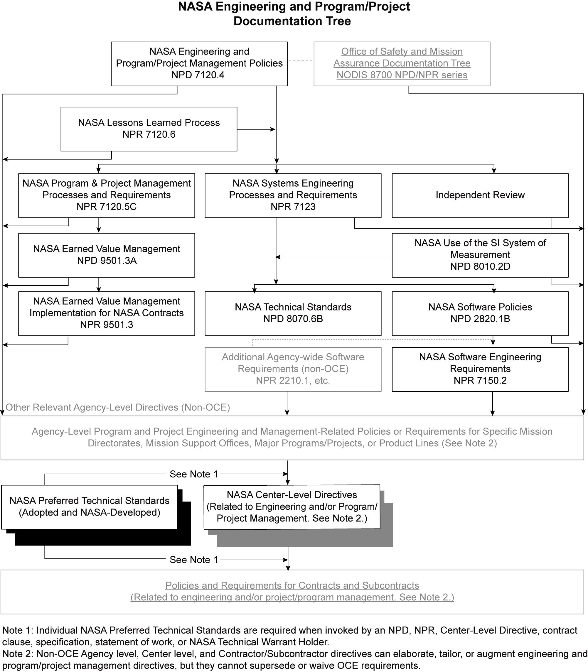
F.1 Tailoring is the documentation and approval of the adaptation of the processes and approach to complying with requirements according to the purpose, complexity, and scope of a NASA program or project. Tailoring, including rationale for modifications, additions, or deletions should be approved by the DGA.
F.2 Each project following this SE NPR needs to tailor to the specific needs of a particular project, phase, or acquisition structure. Tasks that add unnecessary costs, data, and any factors that do not add value to the project need to be eliminated. Tailoring takes the form of modification or addition.
F.3 Tailoring specific tasks requires definition of the depth of detail, level of effort, and the data expected. Tailoring is performed to both breadth and depth based on the project and specific phase of the life cycle. "Tailoring in breadth" deals with factors that can include types and numbers of systems impacted by the development of a new subsystem, the numbers and types of assessments, and numbers and types of reviews. "Tailoring in depth" involves decisions concerning the level of detail needed to generate and substantiate the requirements. The depth of the SE effort varies from project to project in relation to complexity, uncertainty, urgency, and the willingness to accept risk.
F.4 The objectives of the effort, the scope of the SE process, and the breadth and depth of application need to be considered. To assist in defining the depth of application and level of effort, the following should be evaluated as part of the tailoring process of this SE NPR:
a. The level of detail in system definition required from the in-house Government or contracted effort.
b. The directions and limitations of tasks including willingness to accept risk.
c. The scenarios and missions to be examined for each primary system function.
d. A set of measures of effectiveness.
e. Known constraints in areas where they exist but quantitative data is not available.
f. The technology database including identification of key technologies, performance, maturity, cost, risks, schedule, and any limiting criteria on the use of technologies.
g. The factors essential to system success, including those factors related to major risk areas (e.g., budget, resources, and schedule).
h. Technical demonstration and confirmation events that need to be conducted (including technical reviews).
i. The goals and constraints of the project.
j. The organizational and contractual requirements for SE processes.
k. The baseline SE process for the organization and tailoring guidelines.
l. Any cost targets and the acceptable level of risk.
F.5 The basic SE tailoring process can be applied to any development effort (including new developments, modifications, and product improvements) regardless of size or complexity. Attention to scope of the effort and level of output expected is essential. A revolutionary new system development, for example, in Formulation will not usually require formal configuration management audits or formal change control mechanisms. However, conceptual exploration investigation of modifications to an existing developed system may need this type of activity.
F.6 The level of detail expected from the system products of the technical effort needs to be identified. This will scope the depth to which the SE process is executed. For example, functional analysis and synthesis are conducted to a sufficiently detailed depth to identify areas of technical risk based on the life-cycle phase or effort.
F.7 The term "sufficiently detailed" is determined based on the objectives of the project and can be characterized by the information content expected from the physical architecture. Throughout the life cycle, the level of detail may vary since the baseline system may be at one level of detail and product improvements or other modifications may be at a different level of detail. Note that level of detail needed from the technical effort to ensure adequacy of technical definition, design, and development is not synonymous with the level of detail expected for management control and reporting (e.g., cost performance reports).
F.8 The primary output of the SE tailoring process for a project is documented in the SEMP. The form of the SEMP will vary depending on the size, complexity and acceptable cost or risk level of the project.
The following documents were used as reference materials in the development of this appendix:
a. Defense Acquisition University Systems Engineering Fundamentals, Defense Acquisition University Press, Ft. Belvoir, VA 22060, December 2000.
b. International Council on Systems Engineering (INCOSE) Systems Engineering Guide.
This appendix describes the recommended best practices for technical reviews.
a. The MCR will affirm the mission need and examine the proposed mission's objectives and the concept for meeting those objectives. It is an internal review that usually occurs at the cognizant organization for system development.
b. The MCR should be completed prior to entering the concept development phase.
c. Entrance Criteria. The MCR should include, for hardware and software system elements, availability of the products in Table G-1 to the cognizant participants prior to the review.
d. Success Criteria. The review board was able to conclude that the success criteria in Table G-1 was accomplished to complete the objectives of the MCR.
|
Mission Concept Review | |
|
Entrance Criteria |
Success Criteria |
|
|
a. The SRR and/or MDR examines the functional and performance requirements defined for the system and the preliminary program or project plan and ensures that the requirements and the selected concept will satisfy the mission.
b. SRR and/or MDR is typically conducted during the concept development phase following completion of the concept studies phase, following baselining of the Systems Engineering Management Plan (SEMP) and before the preliminary design phase, the Agency Pre-Non-Advocate Review (PNAR), and System Definition Review (SDR).
c. Entrance Criteria. Prior to the execution of the SRR and/orMDR the activities and products identified in Table G-2 should be completed and documentation provided to all participants prior to the review. Also, precursor reviews should be completed.
d. Success Criteria. The review board was able to conclude that the success criteria in Table G-2 was accomplished to complete the objectives of the SRR and/or MDR.
|
System Requirements Review and/or Mission Definition Review |
|
|
Entrance Criteria |
Success Criteria |
|
|
a. The SDR examines the proposed system architecture/design and the flow down to all functional elements of the system.
b. SDR is conducted early in the preliminary design phase, after the Pre-Non-Advocate Review (PNAR) and before the Preliminary Design Review (PDR).
c. Entrance Criteria. Prior to the execution of the SDR, the activities and products identified in Table G-3 should be completed and documentation provided to all participants prior to the review. Also, precursor reviews should be completed.
d. Success Criteria. The review board was able to conclude that the success criteria in Table G-3 was accomplished to complete the objectives of the SDR.
|
System Definition Review | |
|
Entrance Criteria |
Success Criteria |
|
|
b. PDR occurs near the completion of the preliminary design phase as the last review in the Formulation Phase and before the Agency Non-Advocate Review (NAR).
c. Entrance Criteria. Prior to the execution of the PDR the activities and products identified in Table G-4 should be completed and documentation provided to all participants prior to the review. Also, precursor reviews should be completed.
d. Success Criteria. The review board was able to conclude that the success criteria in Table G-4 was accomplished to complete the objectives of the PDR.
|
Preliminary Design Review | |
|
Entrance Criteria |
Success Criteria |
|
|
|
Critical Design Review | |
|
Entrance Criteria |
Success Criteria |
|
|
b. A TRR is held prior to commencement of verification testing.
c. Entrance Criteria. Prior to the execution of a TRR, the activities and products identified in Table G-6 should be completed and documentation provided to all participants prior to the review.
d. Success Criteria. The review board was able to conclude that the success criteria in Table G-6 was accomplished to complete the objectives of a TRR.
|
Test Readiness Review | |
|
Entrance Criteria |
Success Criteria |
|
|
b. The SAR is held late in the fabrication, assembly, integration, and test phase.
c. Entrance Criteria. Prior to the execution of the SAR, the activities and products identified in Table G-7 should be completed and documentation provided to all participants prior to the review.
d. Success Criteria. The review board was able to conclude that the success criteria in Table G-7 was accomplished to complete the objectives of the SAR.
|
System Acceptance Review | |
|
Entrance Criteria |
Success Criteria |
|
|
b. The FRR is held after the system has been configured for flight.
c. Entrance Criteria. Prior to the execution of the FRR, the activities and products identified in Table G-8 should be completed and documentation provided to all participants prior to the review.
d. Success Criteria. The review board was able to conclude that the success criteria in Table G-8 was accomplished to complete the objectives of the FRR:
|
Flight Readiness Review | |
|
Entrance Criteria |
Success Criteria |
|
|
a. The ORR examines the actual system characteristics and the procedures used in the system or product's operation and ensures that all system and support (flight and ground) hardware, software, personnel, procedures, and user documentation accurately reflects the deployed state of the system.
b. The ORR is held at the end of Phase D.
c. Entrance Criteria. Prior to the execution of the ORR, the activities and products identified in Table G-9 should be completed and documentation provided to all participants prior to the review.
d. Success Criteria. The review board was able to conclude that the success criteria in Table G-9 was accomplished to complete the objectives of the ORR.
|
Operational Readiness Review | |
|
Entrance Criteria |
Success Criteria |
|
|
Science and technology development conducted by NASA in BAR, ATD, and IP programs and projects may not be conducted along the same rigorous processes and schedules as FS&GS programs. Depending on the scope and technology readiness level (TRL) of these projects, a streamlined review system may be appropriate. (See NPR 7120.5 for a definition of TRL.) Sound engineering of processes defined in this SE NPR should be applied and reviewed when appropriate. A PTR review schedule with well-defined review entrance and success criteria should be developed in project formulation. Success criteria should ascertain whether sufficient technical maturity has been achieved to support a management decision to proceed to the next phase. In some cases, such as high TRL development efforts, a subset of FS&GS reviews is appropriate (e.g., SRR, PDR, CDR, SAR). PTRs should include both internal and independent external reviewers. Finding and actions from each PRT should be disseminated and resolved after each review.
a. The purpose of the DR is to confirm the decision to terminate or decommission the system and assess the readiness for the safe decommissioning and disposal of system assets.
b. The DR is normally held near the end of routine mission operations upon accomplishment of planned mission objectives. It may be advanced if some unplanned event gives rise to a need to prematurely terminate the mission, or delayed if operational life is extended to permit additional investigations.
c. Entrance Criteria. Prior to the execution of the DR, the activities and products identified in Table G-10 should be completed and documentation provided to all participants prior to the review.
d. Success Criteria. The review board was able to conclude that the success criteria in Table G-10 was accomplished to complete the objectives of the DR.
|
Decommissioning Review | |
|
Entrance Criteria |
Success Criteria |
|
|
a. Peer reviews provide the technical insight essential to ensure product and process quality. Peer reviews are focused, in-depth technical reviews that support the evolving design and development of a product, including critical documentation or data packages. They are often, but not always, held as supporting reviews for technical reviews such as PDR and CDR. A purpose of the peer review is to add value and reduce risk through expert knowledge, infusion, confirmation of approach, identification of defects, and specific suggestions for product improvements.
b. The results of the engineering peer reviews (EPRs) comprise a key element of the review process. The results and issues that surface during these reviews are documented and reported out at the appropriate next higher element level.
c.The peer reviewers should be selected from outside the project, but they should have a similar technical background, and they should be selected for their skill and experience. Peer reviewers should be selected to have as their only concern the technical integrity and quality of the product. Peer reviews should be kept simple and informal. They should concentrate on a review of the documentation and minimize the viewgraph presentations. A "round-table" format rather than a stand-up presentation is preferred. The peer reviews should give the full technical picture of items being reviewed.d.Technical depth should be to a level that allows the review team to gain insight into the technical risks. Rules need to be established to ensure consistency in the peer review process. At the conclusion of the review, a report on the findings and actions must be distributed.
e.Peer reviews must be part of the contract for those projects where systems engineering is done out-of-house.
SE NPR Implementation Plan Select here to view this plan.
SE NPR Center Survey Select here to view this survey.
The following documentsßwere used as reference materials in the development of this SE NPR. The documents are offered as informational sources and are not evoked in this SE NPR, though they may be referenced.
1.ß MIL-STD-499B (draft), SystemsßEngineering.
2.ß ISO/IEC 15288, SystemßLife CycleßProcesses.
3.ß ANSI/EIA 632, Processesßfor EngineeringßSystems.
EIA 632 is a commercial version that evolved from the never released, but fully developed 1994 Mil-Std 499B SystemsßEngineering. It was intended to provide a framework for developing and supporting universal SEßdiscipline for both defense and commercial environments. EIA 632 was intended to be a top-tier standard further defined to lower level tier standards that define specific practices. IEEE 1220 is a second-tier standard that implements EIA 632 by defining one way to practice systems engineering. ISO/IEC 15288 defines system life processesßfor the international set plus for any domainß(i.e., transportation, medical, commercial, et al.).
4.ß CMMI model.
The Capability Maturity Model½ (CMM) IntegrationSM (CMMI) in its present form is a collection of best practices for the "development and maintenance" of both "products and services." The model was developed by integrating practices from four different CMMs-the "source models:" the CMM for software, for systemsßengineering, for integrated product development (IPD), and for acquisition. Organizationsßcan use the model as a guide for improving their ability to develop (or maintain) products (and services) on time, within budget, and with desired quality. During the past decade, many organizations have used CMM and CMM-like concepts to bring order to their development processes. Additionally, it also provides these organizations the framework for enlarging the focus of process improvement to other areas that also affect product development-the discipline of systems engineering. During the past decade, new and effective concepts for organizing developmental work have surfaced and been adopted such as concurrent engineering or the use of integrated teams. Organizations using (or wishing to adopt these ideas) can also find support in the CMMI by using the model with integrated product and process development (IPPD) additions.
5.ß Defense Acquisition University SystemsßEngineeringßFundamentals. Defense Acquisition University Press, Ft. Belvoir, VA, December 2000.
6.ß International Council on Systems EngineeringßSystems Engineering Guide.
7.ß ISO/IEC 19760, A Guide for the Application of ISO/IEC 15288 (System Life Cycle Processes).
8. ISO/AS9100, "Quality Management Systems, Aerospace, Requirements.
Activity(ies), iii, 2, 5, 7, 14, 15, 21, 25, 29, 31, 34, 35, 41, 44, 49, 53, 55, 57, 60, 62, 64, 65, 68, 69, 71, 72, 73, 75, 76, 77, 79, 81, 86, 92, 93, 94, 96, 97, 98, 99, 100
Advanced Technology Development, 1, 30
Analysis of Alternative, 92
Applied Research, 23, 30, 38
Approval, 5, 38, 39
Architecture, iii, iv, 93, 95
Assessment(s), 11, 19, 20, 21, 40, 44, 57, 58, 60, 61, 65, 67, 69, 80, 81, 92, 93, 94, 95, 96, 98
ATD, 1, 30
Authority, iii, 5, 9, 11, 21, 30, 86
BAR, 1
Baseline, 15, 18, 31, 36, 85, 93, 94, 95, 96, 100
Basic and Applied Research, 1
Basic and Applied Research (BAR), 1
Budget, 96
CDR, iv, v, 96
Center Director(s), 9, 10, 11, 15, 16, 17, 18, 19, 20, 88
Common Technical Processes, iii, 7, 13, 14, 15, 21, 23, 40, 64, 86
Configuration Management, iv, 19, 76, 91, 97
Constraint(s), 4, 13, 31, 34, 90, 93, 94, 95, 96, 99, 100
Contractor, 8, 21, 30, 34, 86
Control(s), 10, 21, 27, 38, 64, 69, 70, 74, 93, 95
Criteria
Entrance, 92, 93, 94, 95, 96, 97, 98, 99, 100
Exit, 13, 18, 31, 33, 84, 86
Critical Design Review, iv, v, 96
Customer, 1, 18, 22, 30, 31, 32, 33, 34, 35
Decision Analysis, v, 20, 21, 82
Decommissioning Review, iv, v, 38, 100
Definition
Design Solutions, iv, 16, 17, 41, 42, 45, 46, 47, 48, 49, 50, 51, 52, 57, 58, 59, 63, 66, 70, 86
Stakeholder Expectations, 15, 18
Technical Requirements, iv, 16, 17, 45
Technical Solutions, 21
Design Realization, iv, 21
Disposal, 4, 5, 14, 22, 95, 96
Document(s), iii, iv, 1, 2, 18, 38, 40, 69, 70, 71, 84, 93, 94, 96, 97, 99
Interface Control, 38, 95, 96
Domain, 35
DR, iv, v, 38, 100
Electromagnetic Interference, 95
EMI, 95
Enabling Products, 14, 16, 19, 34, 85, 99
Engineering, 1, 2, 4, 7, 9, 10, 15, 20, 26, 28, 34, 35, 38, 39, 66, 83, 87, 91, 92, 95, 96, 101, 103
Entrance Criteria, 92, 93, 94, 95, 96, 97, 98, 99, 100
Environment(al,s), 1, 2, 34, 35, 38, 95, 97, 98, 99
Exit Criteria, 13, 18, 31, 33, 84, 86
Formulation, 38
Governing Authority, iii, 2, 5, 38, 84
Implementation, iii, iv, 1, 2, 10, 28, 31, 86, 88, 102
Institutional Project, 1
Integrate(d,s), 38, 96
Integration, iv, 95
Interface Control Document, 95, 96
Interface(s)
Technical, 95
IP, 1
Key Performance Parameter, 30, 35
KPP, 30
Life Cycle, iii, iv, 20, 92, 103
Life Cycle Processes, 103
Logical Decomposition, iv, 16, 46, 47
Management
Configuration, iv, 19, 76, 91, 97
Project, 5, 9, 93
Risk, iv, 19, 72, 73, 92
Systems engineering, 1, 5
Systems Engineering, iii, 93, 94
Management Life Cycle(s), 2, 23, 31
MCR, iv, v, 92, 93
Measure of Effectiveness, 17, 18, 30, 92
Measure of Performance, 17, 30, 35, 43, 44, 46, 92
Milestone, 98
Mission, iv, 1, 2, 9, 14, 21, 31, 32, 34, 35, 38, 39, 45, 62, 63, 92, 93, 94, 95, 96, 99
Mission Assurance, 2, 39, 93, 94, 95, 96
Mission Concept Review, iv, v, 92, 93
Mission Directorate, 9, 38
Mission Support Office, 38
MoE, 17, 30
MOP(s), 17, 30, 32, 35, 92
NASA Policy Directive, 2, 5, 9
NASA Procedural Document, 2, 4, 5, 9
NASA Procedural Requirements, iv, 1, 2, 5, 7, 8, 9, 10, 11, 13, 15, 20, 23, 30, 31, 35, 39, 40, 102
Non-Advocate Review, 39, 92, 93
NPD, 2, 5, 9
NPR, iv, 1, 2, 5, 7, 8, 9, 10, 11, 13, 15, 20, 23, 30, 31, 35, 39, 40, 102
OCE, 7, 9, 10, 40
Office of the Chief Engineer, ii, 7, 9, 10, 40
Operational Concepts, 93
Operational Readiness Review, iv, v, 99
Organization, iii, 2, 5, 9, 30, 85, 86
ORR, iv, v, 99
PDR, iv, v, 75, 94, 95, 96
Peer Review, iv, 1, 38, 39, 83, 101
Periodic Technical Review, iv, 25
Phase B, 94
Phase D, 99
Phase(s)
B, 94
D, 99
Implementation, 31
Life Cycle, 2, 8, 15, 18, 23, 26, 31, 33, 84, 86
Plan(s)
EMI/EMC Control, 95
Integration, 95
Project, 39, 83, 87, 92
Project Management, 93
Quality Assurance, 95
Systems Engineering Management (SEMP), iii, 1, 5, 11, 34, 39, 93, 94
Technical, iv, 5, 18, 21, 29, 67, 92, 95
Technical Performance Measurement, 95
Validation, 95, 96
Verification, 96
PR, 1, 39, 83, 101
Preliminary Design Review, iv, v, 75, 94, 95, 96
Process(es)
Assessment, 20, 44, 57, 58, 60, 61, 65, 67, 69, 80, 81
Common Technical, iii, 7, 13, 14, 15, 21, 23, 40, 64, 86
Decision Analysis, v, 20, 82
Definition, 16, 40, 41, 42, 43, 45, 46, 48, 49, 51
Design, iii, 14, 18, 19
Design Realization, iv
Expectation Definition, 43
Life Cycle, 103
Planning, 18, 25, 49, 57, 59, 65, 67, 72, 78
Product Realization, iii, 14, 20
Product Transition, iv, 18, 64
Product Verification, iv, 17, 58
Realization, 51, 52
Stakeholder Expectation Definition, iv
Stakeholder Expectations Definition, 15, 18
Technical, 1, 4, 7, 13, 15, 18, 28, 31, 34, 40, 62, 65, 72, 77, 84, 85, 86
Technical Control, v, 20, 25, 78, 80
Technical Management, iii, 14, 20
Technical Planning, iv, 18, 67
Technical Requirements Definition, iv, 16, 17, 42, 45
Transition, 18, 52, 54, 55, 57, 59, 61, 62, 63, 64
Process(s)
Product Validation, iv, 18, 61
Processes, iii, iv, v, 1, 5, 7, 8, 9, 13, 14, 15, 16, 17, 18, 19, 20, 26, 31, 32, 33, 38, 40, 42, 43, 45, 46, 47, 49, 50, 51, 52, 53, 54, 55, 56, 57, 58, 59, 61, 62, 64, 65, 66, 67, 69, 70, 71, 72, 73, 74, 76, 77, 78, 79, 80, 81, 82, 93, 94, 95, 101, 103
Product Lines, iv, 31
Product Realization Processes, iii, 14, 20
Product(s)
Enabling, 14, 16, 19, 34, 85, 99
Program Management Committee, 27
Project(s)
Institutional, 1, 38
PTR, iv
Request for Proposal, 21
Requests for Action, 26, 93
Requirement(s)
Interface, 49, 94
Software Engineering, 2, 52
System, iv, 31, 35, 93
Requirements Management, iv, 18, 69
Requirements Review, 26, 39, 92
Research
Applied, 23, 30, 38
Basic and Applied (BAR), 1
Review, iv, 1, 5, 8, 11, 25, 26, 27, 32, 34, 38, 39, 50, 64, 73, 78, 79, 85, 90, 92, 93, 94, 95, 96, 97, 98, 99, 100, 101
Review(s)
Confirmation (CR), 38
Continuation (CnR), 38
Continuation (ConR), 38
Critical Design (CDR), iv, v, 96
Decommissioning (DR), iv, v, 38, 100
Flight Readiness (FRR), iv, v, 38, 98, 99
Management, 26
Mission Concept (MCR), iv, v, 92, 93
Non-Advocate (NAR), 39, 92, 93
Operational Readiness (ORR), iv, v, 99
Peer, iv, 38, 101
Periodic Technical (PTR), iv, 25
Preliminary Design (PDR), iv, v, 75, 94, 95, 96
Pre-Non-Advocate (PNAR), 39
Product Definition (PDR), iv, v, 75, 94, 95, 96
Production (PR), 1, 39, 83, 101
System Acceptance (SAR), iv, v, 98
System Definition (SDR), iv, 94
System Definition or Design (SDR), iv, v, 93, 94, 95
System Requirements (SRR), iv, v, 26, 92, 93, 94
Technical, iii, iv, 8, 11, 23, 26, 34, 92, 99
Technical Progress, 26
Test Readiness (TRR), iv, v, 97
RFA, 26
RFP, 21
Risk Management, iv, 19, 72, 73, 92
Roles and Responsibilities, iii, 9, 87
Safety, 1, 2, 25, 34, 35, 39, 45, 46, 81, 87, 94, 95, 96, 97, 99, 100
SAR, iv, v, 98
Schedule, 2, 5, 13, 20, 34, 92, 93, 94, 95, 96
SDR, iv, v, 93, 94, 95
SE, iv, 1, 4, 6, 7, 8, 9, 10, 11, 12, 13, 14, 15, 23, 31, 35, 39, 40, 64, 65, 83, 84, 87, 88, 90, 91, 100, 102, 103
SEMP, iii, 1, 5, 10, 11, 15, 18, 21, 22, 28, 29, 83, 84, 86, 92, 93, 94
SEWG, 10
Shall, 9, 10, 15, 16, 21, 22, 25, 26, 29, 31, 33
Software Design Documents, 96
Software Development Plan, 39, 93
Software Test Plan, 94
SRR, iv, v, 26, 92, 93, 94
Stakeholder, iv, 13, 15, 16, 17, 18, 23, 31, 32, 35, 42
Stakeholder Expectations, iv, 13, 15, 16, 17, 18, 23, 42
System, i, iii, iv, 1, 4, 5, 6, 7, 9, 10, 14, 15, 18, 19, 20, 21, 23, 25, 26, 28, 30, 31, 33, 35, 36, 39, 41, 44, 46, 48, 49, 53, 55, 57, 60, 62, 65, 68, 69, 72, 75, 77, 79, 81, 83, 85, 87, 92, 93, 94, 95, 96, 97, 98, 99, 101, 103
System Acceptance Review, iv, v, 98
System Definition Review, iv, v, 93, 94, 95
System Design Review, iv, v, 93, 94, 95
System Engineering Management Plan, iii, 1, 5, 10, 15, 18, 21, 22, 28, 29, 40, 66, 83, 84, 86, 92, 93, 94
System Engineering Working Group, 10
System Requirements Review, iv, v, 26, 92, 93, 94
System Safety, 93
System(s) Engineering Working Group, 10
Systems Acceptance Review, 98
Systems Engineering, i, iii, iv, 1, 4, 5, 6, 7, 8, 9, 10, 11, 12, 13, 14, 15, 21, 23, 26, 28, 31, 35, 39, 40, 64, 65, 83, 84, 87, 88, 90, 91, 93, 94, 100, 101, 102, 103
Tailoring, iv, 5, 83, 86
Technical Management Processes, iii, 14, 20
Technical Performance Measures, 30, 35, 79
Technical Performance Metrics, 30, 79, 95
Technical Requirements, iv, 5, 16, 17, 45, 94
Technical Team, 1, 5, 15, 21, 22, 26, 29, 35, 74, 93, 94, 95, 96
Test Readiness Review, iv, v, 97
TPM, 30, 79, 95
Training, 15, 32, 66, 97, 99
Transitions, 18, 21, 22, 33, 35, 52, 54, 55, 57, 59, 61, 62, 63, 64, 98
TRR, iv, v, 97
Validation, 15, 17, 49, 57, 59, 61, 62, 78, 86, 93, 95, 96, 99
Verification, 16, 17, 33, 49, 52, 55, 56, 59, 86, 93, 95, 96
Verification and Validation, 33
Waivers, 5, 83, 88, 99
WBS, iv, 14, 15, 16, 17, 18, 33, 34, 35, 37, 41, 44, 46, 49, 53, 55, 57, 60, 62, 63, 65, 68, 69, 72, 75, 77, 79, 81, 85, 87
Work Breakdown Structure, iv, 14, 15, 16, 17, 18, 33, 34, 35, 37, 41, 44, 46, 49, 53, 55, 57, 60, 62, 63, 65, 68, 69, 72, 75, 77, 79, 81, 85, 87
[1]J.A. Moody, W.L. Chapman, F.D. Van Voorhees, A.T. Bahill, Metricsßand Case Studies for Evaluating EngineeringßDesigns (Upper Saddle River, NJ: Prentice Hall, 1997).
[2]The SEMPßis an input to the common technical processesßbut it is not shown in each process diagram in this appendix.