a. This
appendix contains best typical practices as extracted from industry and
national and international standards and as found within the Agency. The
practices may be used by Centers in preparing directives, policies, rules, work
instructions, and other documents implementing SE processes. The
practices of this appendix may also be used in the future assessments of those
plans and processes to provide feedback to the OCE and Centers on the strengths
and weaknesses in the Center's implementation of this SE NPR. These practices
can be expanded and updated as necessary.
b. Each process is
described in terms of purpose, inputs, outputs, and activities. Notes are
provided to further explain a process and to help understand the best practices
included. A descriptive figure is also provided for each process to
illustrate notional relationships between activities within a process and
the sources of inputs and destinations of outputs. Figures in this appendix are
not intended to include all possible inputs, outputs, or intermediate work
products.[2]
c. System Design Processes
a. There are four system design processes applied to each
product-based WBS model from the top to the bottom of the system
structure: (1) Stakeholder Expectation Definition, (2) Technical
Requirements Definition, (3) Logical Decomposition, and (4) Design
Solution Definition. (See Figure 3-2.)
b. During the application of these four processes to a WBS model
it is expected that there will be a need to apply activities from other
processes yet to be completed in this set of processes and to repeat process
activities already performed in order to arrive at an acceptable set of
requirements and solutions. There will also be a need to interact with the
technical management processes to aid in identifying and resolving issues
and making decisions between alternatives.
c. For software products, the technical team should refer to
NPR 7150.2 software design requirements. The technical team should also
ensure that the process implementations comply with NPR 7150.2 software
product realization requirements for software aspects of the system.
C.1.1 Stakeholder Expectations Definition Process
C.1.1.2 Inputs and Sources:
a. Customer expectations (from users and program and/or project)
b. Other stakeholder expectations (from project and/or other
interested parties of the WBS model products - recursive loop).
c. Customer flow-down
requirements from previous level WBS model products (from Design Solution
Definition Process - recursive loop - and Requirements Management and
Interface Management Processes)
C.1.1.3 Outputs and Destinations:
a. Set of validated stakeholder expectations, including interface
requirements (to Technical Requirements ;Definition, Requirements
Management, and Interface Management Processes).
b. Baseline operational concepts (to Technical
Requirements Definition Process and Configuration
Management Processes).
c. Baseline set of enabling product support strategies (to
Technical Requirements Definition Process and Configuration
Management Processes).
d. Measures of Effectiveness (MOEs) (to Technical
Requirements Definition Process and Technical Data Management
Process).
C.1.1.4 Activities
For the WBS model in the system structure, the following
activities are typically performed:
a. Establish a list that identifies customers and other
stakeholders that have an interest in the system and its products.
b. Elicit customer and other
stakeholder expectations (needs, wants, desires, capabilities,
external interfaces, and constraints) from the identified stakeholders.
c. Establish
operational concepts and support strategies based on
stakeholder expected use of the system products over the system's
life.
d. Define stakeholder expectations in acceptable statements that
are complete sentences and have the following characteristics: (1) individually
clear, correct, and feasible to satisfy; not stated as to how it is to be
satisfied; implementable; only one interpretation of meaning; one
actor-verb-object expectation; and can be validated at the level of the
system structure at which it is stated; and (2) in pairs or as a set there
is an absence of redundancy, consistency with respect to terms used, not in
conflict with one another, and do not contain stakeholder expectations of questionable
utility or which have an unacceptable risk of satisfaction.
e. Analyze
stakeholder expectation statements to establish a set of measures
(measures of effectiveness) by which overall system or product
effectiveness will be judged and customer satisfaction will be determined.
f. Validate that the resulting set of
stakeholder expectation statements are upward and downward traceable
to reflect the elicited set of stakeholder expectations and that any anomalies
identified are resolved.
g. Obtain
commitments from customer and other stakeholders that the resultant
set of stakeholder expectation statements is acceptable.
h. Baseline the
agreed to set of stakeholder expectation statements.
C.1.1.5 Process Flow Diagram
a. A typical process flow diagram for the stakeholder
expectations definition process is provided in Figure C-1 with inputs
and their sources and the outputs and their destinations. The
activities of the stakeholder expectations definition process are truncated
to indicate the action and object of the action.
b.The customer flow-down requirements from the design solution
definition process are applicable at levels of the system structure
below the top level. The other stakeholder expectations are applicable at each
level of the system structure to reflect the local management policies,
applicable standards and regulations, and enabling product support needs
for the lower level WBS model products.

Figure C-1 - Stakeholder Expectation Definition
Process
C.1.2 Technical
Requirements Definition Process
C.1.2.2 Inputs and Sources:
a. Baselined set of stakeholder expectations, including interface
requirements (from Stakeholder Expectations Definition and
Configuration Management Processes).
b.Baselined Concept of Operation (from
Stakeholder Expectations Definition and Configuration
Management Processes).
c. Baselined Enabling Product Support Strategies (from
Stakeholder Expectations Definition and Configuration
Management Processes).
d.Measures of Effectiveness (from
Stakeholder Expectations Definition and Technical Data
Management Processes).
C.1.2.3 Outputs and Destinations:
a. Set of validated technical requirements that represents a
reasonably complete description of the problem to be solved, including
interface requirements (to Logical Decomposition and Requirements and
Interface Management Processes).
b.Sets of MOPs that when met will satisfy the MOE to which a set
is related (to Logical Decomposition and Technical Data Management
Processes).
c. A set of critical technical performance measures (TPMs) that if not
met will put the project in cost, schedule or performance risk (to
Technical Assessment Process).
C.1.2.4 Activities
For the WBS model in the system structure, the following
activities are typically performed:
a. Analyze the scope of the technical problem to be solved to identify and
resolve the design boundary that identifies: (1) which system functions
are under design control and which are not; (2) expected interaction among
system functions (data flows, human responses, and behaviors); (3) external
physical and functional interfaces (mechanical, electrical, thermal, data,
procedural) with other systems; (4) required capacities of system products; (5)
timing of events, states, modes, and functions related to operational
scenarios; and (6) emerging or maturing technologies necessary to make
requirements.
b.Define
constraints affecting the design of the system or products or how the
system or products will be able to be used.
c. Define functional and behavioral expectations for the system or
product in acceptable technical terms for the range of anticipated uses of
system products as identified in the concept of operations. This permits
separation of defined stakeholder expectation functions and behaviors
that belong to a lower level in the system structure and to allocate them to
the appropriate level.
d.Define the
performance requirements associated with each defined functional and behavioral
expectation.
e. Define technical requirements in acceptable "shall" statements that
are complete sentences with a single "shall" per numbered statement and have
the following characteristics: (1) individually clear, correct, and feasible to
satisfy; not stated as to how it is to be satisfied; implementable; only one
interpretation of meaning; one actor-verb-object requirement; and can be
validated at the level of the system structure at which it is stated; and
(2) in pairs or as a set there is an absence of redundancy, consistent with
respect to terms used, not in conflict with one another, and form a set of
"design-to" requirements.
f.
Validate that the resulting technical requirement statements (1)
have bidirectional traceability to the
baselined stakeholder expectations; (2) were formed using valid
assumptions; and (3) are essential to and consistent with designing and
realizing the appropriate product solution form that will satisfy the
applicable product-line life-cycle phase exit criteria.
g. Define
MOPs for each identified measure of effectiveness (MOE) that cannot
be directly used as a design-to technical requirement.
h. Define
appropriate TPMs by which technical progress will be assessed.
i.
Establish the
technical requirements baseline.
C.1.2.5 Process Flow Diagram
A typical process flow diagram for the technical
requirements definition process is provided in Figure C-2 with inputs and
their sources and the outputs and their destinations. The activities of the
technical requirements definition process are truncated to indicate the action
and object of the action.
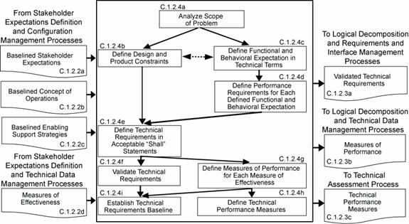
Figure C-2 - Technical Requirements Definition Process
C.1.3 Logical
Decomposition Process
C.1.3.2 Inputs and Sources:
a. The baseline set of validated technical requirements, including
interface requirements (from Technical Requirements Definition and
Configuration Management Processes).
b.The defined MOPs (from Technical
Requirements Definition and Technical Data Management Processes).
C.1.3.3 Outputs and Destinations:
a. Set of validated derived technical requirements, including interface
requirements (to Design Solution Definition and Requirements and Interface
Management Processes).
b.The set of logical decomposition models (to Design Solution
Definition and Configuration Management Processes).
c. Logical decomposition work products (to Technical Data Management
Processes).
C.1.3.4 Activities:
For the WBS model in
the system structure, the following activities are typically performed:
a. Define one or
more logical decomposition models based on the defined technical
requirements to gain a more detailed understanding and definition of the
design problem to be solved.
b.Allocate the
technical requirements to the logical decomposition models to form a
set of derived technical requirement statements that have the following
characteristics:
1.Describe functional and performance, service and attribute, time, and
data flow requirements, etc., as appropriate for the selected set of logical
decomposition models.
2.Individually are complete sentences and are clear, correct, and feasible
to satisfy; not stated as to how to be satisfied; implementable; only have one
interpretation of meaning, one actor-verb-object expectation; and can be
validated at the level of the system structure at which it is stated.
3.In pairs or as a set, have an absence of redundancy, are adequately
related with respect to terms used, and are not in conflict with one another.
4.Form a set of detailed "design-to" requirements.
c. Resolve derived
technical requirement conflicts.
d.Validate that
the resulting set of derived technical requirements have: (1)
bidirectional traceability with the set of validated technical requirements and
(2) assumptions and decision rationale consistent with the source set of
technical requirements.
e. Establish the
derived technical requirements baseline.
C.1.3.5 Process Flow Diagram
A typical process flow diagram for logical
decomposition is provided in Figure C-3 with inputs and their sources and the
outputs and their destinations. The activities of the logical
decomposition process are truncated to indicate the action and object of the
action.
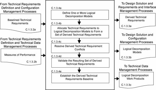
Figure C-3 - Logical Decomposition Process
C.1.4 Design
Solution Definition Process
C.1.4.2 Inputs and Sources:
a. A baselined set of logical decomposition models (from Logical
Decomposition and Configuration Management Processes).
b.A
baseline set of derived technical requirements including interface
requirements (from Logical Decomposition and Configuration
Management Processes).
C.1.4.3 Outputs and Destinations:
The specified requirements that describe the
system design solution definition for the products of the WBS model
under development include:
a. A WBS model design solution definition set of requirements for the
system (see WBS definition in Appendix A), including specification
configuration documentation and external interface specification (to
Requirements and Interface Management Process).
b.A
baseline set of "make-to," "buy-to," "reuse-to," or set of "assemble and
integrate-to" specified requirements (specifications and configuration
documents) for the desired end product of the WBS model, including
interface specifications (to Requirements and Interface Management Process).
c. The initial
specifications for WBS model subsystems for flow down to the next
applicable lower level WBS models, including interface specifications (to
Stakeholder Expectations Definition, and Requirements and Interface
Management Processes).
d.The requirements for enabling products that will be needed to
provide life-cycle support to the end products, including interface
requirements (to
Stakeholder Expectations Definition Process for development
of enabling products or to Product Implementation Process for acquisition
of existing enabling products, and Requirements and Interface Management
Processes).
e. A product
verification plan that will be used to demonstrate that the product
generated from the design solution definition conforms to the design solution
definition specified requirements (to Product Verification Process).
f.
A product
validation plan that will be used to demonstrate that the product
generated from the design solution definition conforms to its set of
stakeholder expectations (to Product Validation Process).
g. Baseline operate-to and logistics procedures (to Technical Data
Management Process).
C.1.4.4 Activities
For the WBS model in the system structure, the following
activities are typically performed:
a. Define
alternative solutions for the system end product being developed or
improved that are consistent with derived technical requirements and
non-allocated technical requirements, if any.
b.Analyze each alternative solution against defined criteria such as:
satisfaction of external interface requirements; technology requirements;
off-the-shelf availability of products; physical failure modes, effects and
criticality; life-cycle cost and support considerations; capacity to evolve;
make vs. buy; standardization of products; integration concerns; and context of
use issues of operators considering tasks, location, workplace equipment, and
ambient conditions.
c. Select the best
solution alternative based on the analysis results of each alternative solution
and technical decision analysis recommendations.
d.Generate the
full design description of the selected alternative solution in a form
appropriate to the product-line life-cycle phase, location of the
WBS model in the system structure, and phase exit criteria to
include: (1) system specification and external interface specifications;
(2) end product specifications, configuration description documents, and
interface specifications; (3) end product subsystem initial specifications, if
subsystems are required; (4) requirements for associated supporting enabling
products; (5) end product verification plan; (6) end product
validation plan; and (7) applicable logistics and operate-to procedures.
e. Verify that
the design solution definition: (1) is realizable within
constraints imposed on the technical effort; (2) has specified
requirements that are stated in acceptable statements and have bidirectional
traceability with the derived technical requirements, technical requirements
and stakeholder expectations; (3) has decisions and assumptions made in
forming the solution consistent with its set of derived technical requirements,
separately allocated technical requirements, and identified system product
and service constraints.
f.
Baseline the
design solution definition specified requirements including the specifications
and configuration descriptions.
g. Initiate
development or acquisition of the life cycle supporting enabling
products needed, as applicable, for research, development, fabrication,
integration, test, deployment, operations, sustainment, and disposal.
h. Initiate
development of the system products of the next lower level WBS model,
if any.
C.1.4.5 Process Flow Diagram
A typical process flow diagram for design solution
definition is provided in Figure C-4 with inputs and their sources and the
outputs and their destinations. The activities of the design solution
definition process are truncated to indicate the action and object of the
action.
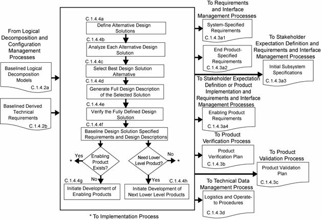
Figure C-4 - Design Solution Definition Process
There are five product realization processes. Four of the
product realization processes are applied to each end product of a
WBS model from the bottom to the top of the system structure: (1)
either product implementation or product integration, (2) product
verification, (3) product validation, and (4) product transition. (See Figure 3-2) The form of the end product realized will be
dependent on the applicable product-line life-cycle phase, location within the
system structure of the WBS model containing the end product, and the exit
criteria of the phase. Typical early phase products are in the form of
reports, models, simulations, mockups, prototypes, or demonstrators. Later
phase product forms include the final mission products, including payloads
and experiment equipment. For software products, the technical team should
refer to NPR 7150.2 for software product realization requirements. The
technical team should also ensure that the process implementations comply
with NPR 7150.2, NASA Software Engineering Requirements for software aspects of
the system. The product realization process descriptions that follow assume
that each lowest level product goes through the sequencing shown in Figure
C-5a. Exceptions will need to be planned according to what has and has not been
already performed.
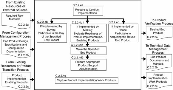
Figure C-5a -Sequencing of Design Realization Processes
C.2.1.2 Inputs and Sources:
a. Raw materials needed to make the end product (from existing resources or
external sources).
b.End product design solution definition specified requirements
(specifications) and configuration documentation for the end product of the
applicable WBS model, including interface specifications, in the form
appropriate to satisfying the product-line life-cycle phase exit
criteria (from Configuration Management Process).
c. Product implementation enabling products (from existing resources
or Product Transition Process for enabling product realization).
C.2.1.3 Outputs and Destinations:
a. Made, bought,
or reused end product in the form appropriate to the product-line life-cycle
phase and to satisfy exit criteria (to Product Verification Process).
b.Documentation
and manuals in a form appropriate for satisfying the life-cycle phase exit
criteria, including "as-built" product descriptions and "operate-to" and maintenance
manuals (to Technical Data Management Process).
c. Product implementation work products needed to provide reports, records,
and non-deliverable outcomes of process activities (to Technical Data
Management Process).
C.2.1.4 Activities
For the WBS model in the system structure, the following
activities are typically performed:
a. Prepare to conduct product implementation to include (1) preparing a
product implementation strategy and detailed planning and procedures; and (2)
determining whether the product configuration documentation is adequately
complete to conduct the type of product implementation as applicable for the
product-line life-cycle phase, location of the product in the
system structure, and phase exit criteria.
b.If the strategy is for buying an existing product, participate in the
buy of the product including (1) review of the technical information made
available by vendors; (2) assisting in the preparation of requests for
acquiring the product from a vendor; (3) assisting in the inspection of the
delivered product and the accompanying documentation; (4) determination of
whether the vendor conducted product
,validation or if it will need to be
done by a project technical team and (5) determination of the availability of
enabling products to provide test, operations, and maintenance support and
disposal services for the product.
c. If the strategy is to reuse a product that exists in the Government inventory,
participate in the acquiring of the reuse product including: (1) review of
the technical information made available for the specified product to be
reused; (2) determination of supporting documentation and user manuals
availability; (3) determination of avilability of enabling
products to provide test, operations, and maintenance support and
disposal services for the product; (5) assisting in the requests for
acquiring the product from Government sources; and (4) assisting in the
inspection of the delivered product and the accompanying documentation.
d.If the strategy is to make the product,
1.Evaluate the readiness of the product implementation enabling
products to conduct the making of the product.
2.Make the specified product in accordance with the specified
requirements, configuration documentation, and applicable standards.
3.Prepare appropriate product support documentation such as integration
constraints and/or special procedures for performing product
verification and product validation.
e. Capture work
products and related information generated while performing the product
implementation process activities.
C.2.1.5 Process Flow Diagram
C.2.1.5.1 Atypical process
flow diagram for product implementation is provided in Figure C-5b with inputs
and their sources and the outputs and their destinations. The
activities of the product implementation process are truncated to indicate
the action and object of the action.
C.2.1.5.2 The path that products from
the three sources in Figure C-5b take with respect to product verification,
product validation, and product transition vary based on:
a. Whether the products bought have been verified and/or validated by the
vendor.
b.Whether reuse products that come from within the organization have
been verified and/or validated.
c. Whether the customer for the product desires to do the product
validation or have the developer perform the product validation.
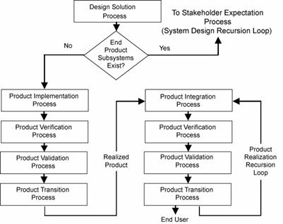
Figure C-5b - Product Implementation Process
C.2.2.2 Inputs and Sources:
a. Lower-level products to be assembled and integrated (from Product
Transition Process).
b.End product design definition specified requirements (specifications)
and configuration documentation for the applicable WBS model, including
interface specifications, in the form appropriate to satisfying the
product-line life-cycle phase exit criteria (from Configuration
Management Process).
c. Product integration enabling products (from existing resources or
Product Transition Process for enabling product realization).
C.2.2.3 Outputs and Destinations:
a. Integrated product(s)
in the form appropriate to the product-line life-cycle phase and to
satisfy phase exit criteria (to Product Verification Process).
b.Documentation
and manuals in a form appropriate for satisfying the life-cycle phase exit
criteria, including "as-integrated" product descriptions and "operate-to" and
maintenance manuals (to Technical Data Management Process).
c. Product integration work products needed to provide reports, records,
and non-deliverable outcomes of process activities (to Technical Data
Management Process).
C.2.2.4 Activities
For the WBS model in the system structure, the following
activities are typically performed
a. Prepare to conduct product integration to include (1) preparing a
product integration strategy, detailed planning for the integration, and
integration sequences and procedures; and (2) determining whether the product
configuration documentation is adequately complete to conduct the type of
product integration applicable for the product-line life-cycle phase, location
of the product in the system structure, and management phase exit
criteria.
b. Obtain lower level products required to assemble and integrate into the
desired product.
c. Confirm that
the received products that are to be assembled and integrated have been
validated to demonstrate that the individual products satisfy the agreed to set
of stakeholder expectations, including interfaces requirements.
d.Prepare the
integration environment in which assembly and integration will take place
to include evaluating the readiness of the product integration enabling
products and the assigned workforce.
e. Assemble and
integrate the received products into the desired end product in accordance with
the specified requirements, configuration documentation, interface
requirements, applicable standards, and integration sequencing and procedures.
f. Prepare appropriate product support documentation such as special
procedures for performing product verification and product validation.
g. Capture work
products and related information generated while performing the product
integration process activities.
C.2.2.5 Process Flow Diagram
A typical process flow diagram for product integration
is provided in Figure C-6 with inputs and their sources and the outputs and
their destinations. The activities of the product integration process are
truncated to indicate the action and object of the action.

Figure C-6 - Product Integration Process
C.2.3.2 Inputs and Sources:
a. End product to be verified (from Product
Implementation Process or Product Integration Process).
b. End product specification
and configuration baselines, including interface specifications, to which the
product being verified was generated (from Technical Data Management Process).
c. Product verification plan (from Design Solution Definition
Process and Technical Planning Process)
d.Product verification enabling products (from existing
resources or Product Transition Process for enabling product realization).
C.2.3.3 Outputs and Destinations:
a. A verified end product (to Product Validation Process).
b. Product verification results (to Technical Assessment Process).
c. Completed
verification report to include for each specified requirement: (1) the
source paragraph references from the baseline documents for derived
technical requirements, technical requirements and
stakeholder expectations; (2) bidirectional traceability among these
sources; (3) verification type(s) to be used in performing verification of the
specified requirement; (4) reference to any special equipment, conditions, or
procedures for performing the verification; (5) results of verification
conducted; (6) variations, anomalies, or out-of-compliance results; (7)
corrective actions taken; and (8) results of corrective actions (to Technical
Data Management Process).
d. Product verification work products needed to provide reports,
records, and non-deliverable outcomes of process activities (to
Technical Data Management Process).
C.2.3.4 Activities
For the WBS model in the system structure, the following
activities are typically performed:
a. Prepare to conduct product verification to include as applicable to
the product-line life-cycle phase and WBS model location in the
system structure: (1) reviewing the product verification plan for
specific procedures, constraints, conditions under which verification will take
place, pre and post verification actions, and criteria for determining the
success or failure of verification methods and procedures; (2) arranging the
needed product verification enabling products and support resources; (3)
obtaining the end product to be verified; (4) obtaining the specification and
configuration baseline against which the verification is to be made; and
(5) establishing and checking the verification environment to ensure readiness
for performing the verification.
b.Perform the
product verification in accordance with the product verification
plan and defined procedures to collect data on each specified requirement
with specific attention given to MOPs.
c. Analyze the
outcomes of the product verification to include identification of
verification anomalies, establishing recommended corrective actions, and/or
establishing conformance to each specified requirement under controlled
conditions.
d.Prepare a
product verification report providing the evidence of product conformance
with the applicable design solution definition specified requirements
baseline to which the product was generated including bidirectional
requirements traceability and corrective actions taken to correct anomalies of
verification results.
e. Capture the
work products from the product verification.
C.2.3.5 Process Flow Diagram
A typical process flow diagram for product
verification is provided in Figure C-7 with inputs and their sources and the
outputs and their destinations. The activities of the product verification
process are truncated to indicate the action and object of the action.

Figure C-7 - Product Verification Process
C.2.4 Product
Validation Process
C.2.4.2 Inputs and Sources:
a. End product to be validated (from Product Verification Process).
b.Stakeholder requirements
baseline (from Configuration Management Process).
c. Product validation plan (from Design Solution Definition
Process and Technical Planning Process)
d.Product validation enabling products (from existing resources
or Product Transition Process for enabling product realization).
C.2.4.3 Outputs and Destinations:
a. A validated end product (to Transition Process).
b.Product validation results (to Technical Assessment Process).
c. Completed
validation report to include for each stakeholder expectation or
subset of stakeholder expectations involved with the validation, for example:
(1) the source requirement paragraph reference from the stakeholder
expectations baseline; (2) validation type(s) to be used in establishing
compliance with selected set of stakeholder expectations and match with each
source expectation referenced; (3) identification of any special equipment,
conditions or procedures for performing the validation that includes referenced
expectation; (4) results of validation conducted with respect to the referenced
expectation; (5) deficiency findings (variations, anomalies or
out-of-compliance results); (6) corrective actions taken; and (7) results of
corrective actions (to Technical Data Management Process).
d.Product validation work products needed to provide reports,
records, and non-deliverable outcomes of process activities (to
Technical Data Management Process).
C.2.4.4 Activities
For the WBS model in the system structure, the following
activities are typically performed:
a. Prepare to
conduct product validation to include as applicable to the product-line
life-cycle phase and product location in the system structure: (1)
reviewing the product validation plan for specific procedures,
constraints, conditions under which validation will take place, pre and post
validation actions, and criteria for determining the success or failure of
validation methods and procedures; (2) arranging the needed product validation
enabling products and support resources; (3) obtaining the end product to
be validated; (4) obtaining the
stakeholder expectations baseline against which the validation
is to be made; and (5) establishing and checking out the validation
environment to ensure readiness for performing the validation.
b.Perform the
product validation in accordance with the product validation plan and
defined procedures to collect data on performance of the product against
stakeholder expectations with specific attention given to MOEs.
c. Analyze the
outcomes of the product validation to include identification of validation
anomalies, establishing recommended corrective actions, and/or establishing
conformance to stakeholder expectations under operational conditions
(actual, analyzed or simulated).
d.A product
validation report providing the evidence of product conformance with the
stakeholder expectations baseline including corrective actions
taken to correct anomalies of validation results
e. Capture the
work products from the product validation.
C.2.4.5 Process Flow Diagram
A typical process flow diagram for product
validation is provided in Figure C-8 with inputs and their sources and the
outputs and their destinations. The activities of the product validation
process are truncated to indicate the action and object of the action.
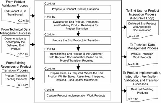
Figure C-8 - Product Validation Process
C.2.5 Product
Transition Process
C.2.5.2 Inputs and Sources:
a. End product or products to be transitioned (from Product Validation
Process).
b.Documentation including
manuals, procedures and processes that are to accompany the end product
(from Technical Data Management Process).
c. Product transition enabling products to include packaging
materials, containers, handling equipment, and storage, receiving and shipping
facilities (from existing resources or Product Transition Process for
enabling product realization).
C.2.5.3 Outputs and Destinations:
a. Delivered end
product with applicable documentation including manuals, procedures and
processes in a form consistent with the product-line life-cycle
phase and location of the product in the system structure (to end
user or Product Integration Process - recursive loop).
b.Product transition work products needed to provide reports,
records, and non-deliverable outcomes of process activities (to
Technical Data Management Process).
c. Realized enabling products from existing enabling products and
services or from applying the common technical processes to develop and
realize (to Product Implementation, Integration, Verification,
Validation and Transition Processes, as appropriate)
C.2.5.4 Activities
For the WBS model in the system structure, the following
activities are typically performed:
a. Prepare to
conduct product transition to include (1) preparing a product
implementation strategy to establish the type of product transition to be made
(to the next higher level customer for product integration or to an end
user); and (2) reviewing related end product stakeholder expectations and
design solution definition specified requirements to identify special
transition procedures and enabling product needs for the type of product
transition, if any, for packaging, storage, handling, shipping/transporting,
site preparation, installation, and/or sustainment.
b.Evaluate the
end product, personnel, and enabling product readiness for product
transition including: (1) availability and appropriateness of the
documentation that will be packaged and shipped with the end product; (2)
adequacy of procedures for conducting product transition; (3) availability and
skills of personnel to conduct product transition; and (4) availability of
packaging materials/containers, handling equipment, storage facilities, and
shipping/transporter services.
c. Prepare the end product for transition to include the packaging and
moving the product to the shipping/transporting location and any intermediate
storage.
d.Transition the end product with required documentation to the
customer based on the type of transition required, e.g., to the next
higher level WBS model for product integration or to the end user.
e. Prepare sites,
as required, where the end product will be stored, assembled, integrated,
installed, used, and/or maintained, as appropriate for the life-cycle phase,
position of the end product in the system structure, and
customer agreement.
f.Capture work
products from product transition process activities.
C.2.5.5 Process Flow Diagram
A typical process flow diagram for product
transition is provided in Figure C-9 with inputs and their sources and the
outputs and their destinations. The activities of the product transition
process are truncated to indicate the action and object of the action.
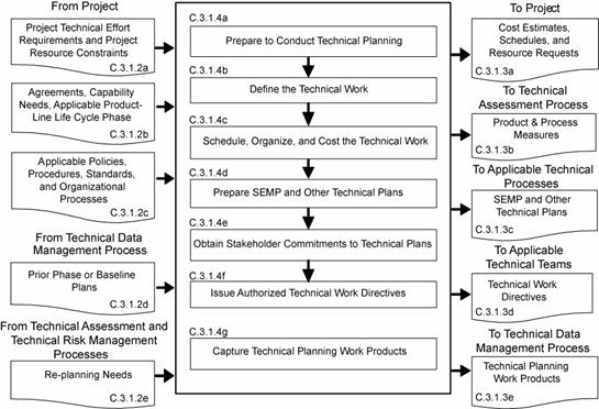
Figure C-9 - Product Transition Process
There are eight technical management processes-Planning,
Requirements Management, Interface Management, Risk Management, Configuration
Management, Technical Data Management, Assessment, and Decision Analysis. (See Figure 3-2.)These technical management processes are
intended to supplement the management requirements defined in NPR 7120.5.
NPR 7120.5 provides program and project managers with the technical
activities that they are required to be cognizant of and are responsible for.
On the other hand, the technical management process in this SE NPR: (1) provide
the technical team their requirements for planning, monitoring and
controlling the technical effort as well as the technical decision analysis
requirements for performing tradeoff and effectiveness analyses to support
decisionmaking throughout the technical effort; (2) focus on (a)
completion of technical process planning (preparation of the SEMP and
other technical plans), (b) technical progress assessment (using technical
measures and conducting technical reviews to assess progress against the
SEMP and defined technical requirements), and (c) control of product
requirements, product interfaces, technical risks, configurations, technical
data and include ensuring that common technical
process implementations comply with NPR 7150.2 software product
realization requirements for software aspects of the system. Documentation
produced through each technical management process should be managed and
dispositioned as Federal records.
C.3.1
Technical Planning Process
C.3.1.2 Inputs and Sources:
a. Project technical effort requirements and project resource
constraints (from the project).
b.Agreements, capability needs and applicable product-line life-cycle
phase(s) (from the project).
c. Applicable policies, procedures, standards, and organizational
processes (from the project).
d.Prior product-line life-cycle phase or baseline plans (from
Technical Data Management Process).
e. Re-planning needs (from Technical Assessment and Technical Risk
Management Processes).
C.3.1.3 Outputs and Destinations:
a. Technical work cost estimates, schedules, and resource needs, e.g.,
funds, workforce, facilities, and equipment (to project).
b.Product and process measures needed to assess progress of the
technical effort and the effectiveness of processes (to Technical Assessment
Process).
c. The SEMP and other technical plans that support implementation
of the technical effort (to all processes; applicable plans to Technical
Processes).
d.Technical work directives, e.g., work packages or task orders with work
authorization (to applicable technical teams).
e. Technical planning work products needed to provide reports, records, and
nondeliverable outcomes of process activities (to Technical Data
Management Process).
C.3.1.4 Activities
For the WBS model in the system structure, the following
activities are typically performed:
a. Prepare to conduct technical planning to include:
1.Preparing or updating a planning strategy for each of the common
technical processes of this SE NPR.
2.Determining:
a) deliverable work
products from technical efforts.
b) technical
reporting requirements.
c) other technical
information needs for reviews or satisfying product-line life-cycle
management phase entry or exit criteria.
d) product and
process measures to be used in measuring technical performance, cost, and
schedule progress.
e) key or critical
technical events with entry and success criteria.
f) data
management approach for data collection and storage and how measurement data
will be analyzed, reported, and dispositioned as Federal records.
g) technical risks
that need to be addressed in the planning effort.
h) tools and
engineering methods to be employed in the technical effort.
i) approach to
acquiring and maintaining the technical expertise needed (training and skills
development plan).
b.Define the
technical work to be done to include associated technical, support, and
management tasks needed to generate the deliverable products and satisfy entry
and success criteria of key technical events and the applicable
product-line life-cycle management phase.
c. Schedule,
organize, and cost the technical effort.
d.Prepare the
SEMP and other technical plans needed to support the technical effort
and perform the technical processes.
e. Obtain
stakeholder commitments to the technical plans.
f. Issue authorized
technical work directives to implement the technical work.
g. Capture work
products from technical planning activities
C.3.1.5 Process Flow Diagram
A typical process flow diagram for technical
planning is provided in Figure C-10 with inputs and their sources and the
outputs and their destin,ations. The activities of the technical planning process are truncated to indicate the action and object of the
action.

Figure C-10 - Technical Planning Process
C.3.2 Requirements
Management Process
C.3.2.2 Inputs and Sources:
a. Expectations and requirements to be managed (from System Design Processes).
b. Requirement change requests (the project and Technical Assessment
Process).
c. TPM estimation/evaluation results (from Technical Assessment
Process)
d.Product verification and product validation results (from
Product Verification and Validation Processes)
C.3.2.3 Outputs and Destinations:
a. Requirement documents (to Configuration Management Process).
b.Approved changes to requirement baselines (to Configuration
Management Process).
c. Requirements
management work products needed to provide reports, records and non-deliverable
outcomes of process activities (to Technical Data Management Process).
C.3.2.4 Activities
For the WBS model in the system structure, the following
activities are typically performed:
a. Prepare to conduct requirements management to include:
1. Preparing or updating a strategy and procedures for:
a) establishing that
expectation and requirement statements, singularly and as a whole, are prepared
in accordance with established formats and rules.
b) identifying
expectations and requirements to be managed, expectation and requirement
sources, allocation and traceability of requirements, and linking product
expectations and requirements with costs, weight, and power allocations as
applicable
c) formal
initiation, assessment, review, approval and disposition of
engineering change proposals and changes to expectation and requirements
baseline.
2.Selecting or updating an appropriate requirements management tool.
3.Training technical team members in the established
requirements management procedures and in the use of the selected/updated
requirements management tool.
b.Conduct requirements management to include: (1) capturing, storing
and documenting the expectations and requirements; (2) establishing that
expectation and requirement statements are compliant with format and other
established rules; (3) confirming that each established requirements
baseline has been validated; and (4) identifying and analyzing
out-of-tolerance system-critical technical parameters and unacceptable
validation and verification results and proposing requirement
appropriate changes to correct out-of-tolerance requirements.
c. Conduct expectation and requirements traceability to include: (1)
tracking expectations and requirements between baselines, especially MOEs,
MOPs, and TPMs, and (2) establishing and maintaining appropriate
requirements compliance matrixes that contain the requirements, bidirectional
traceability, compliance status, and any actions to complete compliance.
d.Manage expectation and requirement changes to include: (1) reviewing
engineering change proposals (ECPs) to determine any changes to
established requirement baselines, (2) implementing formal change procedures
for proposed and identified expectation or requirement changes, and (3)
disseminating the approved change information.
e. Capture work products from requirements management process activities to
include maintaining and reporting information on the rationale for and
disposition and implementation of change actions, current requirement
compliance status, and expectation and requirement baselines.
C.3.2.5 Process Flow Diagram
A typical process flow diagram for requirements
management is provided in Figure C-11 with inputs and their sources and the
outputs and their destinations. The activities of the requirements
management process are truncated to indicate the action and object of the
action.
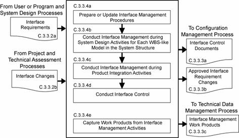
Figure C-11 - Requirements Management Process
C.3.3 Interface
Management Process
C.3.3.2 Inputs and Sources:
a. Internal and external functional and physical interface
requirements for the products of a WBS model (from user or program
and System Design Processes).
b.Interface change requests (from project, and Technical Assessment
Processes).
C.3.3.3 Outputs and Destinations:
a. Interface Control Documents (to Configuration
Management Processes).
b.Approved interface requirement changes (to Configuration
Management Process)
c. Interface management work products needed to provide reports, records,
and non-deliverable outcomes of process activities (to Technical Data
Management Process)
C.3.3.4 Activities
For the WBS model in the system structure, the following activities
are typically performed:
a. Prepare or
update interface management procedures for (1) establishing interface
management responsibilities for those interfaces that are part of agreement
boundaries, (2) maintaining and controlling identified internal and external
physical and functional interfaces, (3) preparing and maintaining appropriate
physical and functional interface specifications or interface control
documents and drawings to describe and control interfaces external to
the system end product, (4) identifying interfaces between system products
(including humans) and among configuration management items, (5)
establishing and implementing formal change procedures for interface evolution,
(6) disseminating the needed interface information for integration into
technical effort activities and for external interface control, and
(7) training technical teams and other applicable support and
management personnel in the established interface management procedures.
b.Conduct interface management during system design
activities for each WBS model in the system structure to include: (1)
integrating the interface management activities with requirements
management activities; (2) analyzing the concept of operations to identify
critical interfaces not included in the stakeholder set of expectations;
(3) documenting interfaces both external and internal to each WBS model as the
development of the system structure emerges and interfaces are added and
existing interfaces are changed; (4) documenting origin, destination, stimulus,
and special characteristics of interfaces; (5) maintaining the design solution
definition for internal horizontal and vertical interfaces between WBS models
in the system structure; (6) maintaining horizontal traceability of interface
requirements across interfaces and capturing status in the established
requirements compliance matrix; and (7) confirming that each interface control
document or drawing that is established has been validated with parties on
both sides of the interface.
c. Conduct interface management during product integration
activities to include: (1) reviewing product integration procedures to
ensure that interfaces are marked to ensure easy and correct
assembly/connection with other products, (2) identifying product integration
planning to identify interface discrepancies, if any, and report to the proper
technical team or technical manager, (3) confirming that a pre-check is
completed on all physical interfaces before connecting products together, (4)
evaluating assembled products for interface compatibility, (5) confirming that
product verification and product validation plans/procedures include
confirming internal and external interfaces, and (6) preparing an interface
evaluation report upon completion of integration and product verification and
product validation.
d.Conduct
interface control to include: (1) managing interface changes within the
system structure, (2) identifying and tracking proposed and directed
changes to interface specifications and interface control documents and
drawings, (3) confirming that the vertical and horizontal interface issues are
analyzed and resolved when a change affects products on both sides of the
interface, (4) controlling traceability of interface changes including source
of the change, processing methods and approvals, and (5) disseminating the
approved interface change information for integration into technical efforts at
every level of the project.
e. Capture work
products from interface management activities.
C.3.3.5 Process Flow Diagram
A typical process flow diagram for interface
management is provided in Figure C-12 with inputs and their sources and the
outputs and their destinations. The activities of the interface management
process are truncated to indicate the action and object of the action.
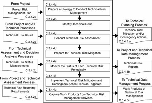
Figure C-12 - Interface Management Process
C.3.4Technical Risk Management Process
C.3.4.2 Inputs and Sources:
a. Project Risk Management Plan (from project)
b.Technical risk issues (from project and other common technical
processes).
c. Technical risk status measurements (from Technical Assessment and
Decision Analysis Processes).
d.Technical risk reporting requirements (from project and Technical
Planning Process).
C.3.4.3 Outputs and Destinations:
a. Technical risk mitigation and/or contingency actions (to Technical
Planning Process for re-planning and/or re-direction).
b.Technical risk reports (to project and Technical Data Management
Process).
c. Work products from technical risk management activities (to
Technical Data Management Process).
C.3.4.4 Activities
For the WBS model in the system structure, the following
activities are typically performed; (NPR 8000.4, Risk Management Procedural
Requirements, is to be used as a source document for defining this process and
implementing procedures.)
a. Prepare a strategy to conduct technical risk management to include:
(1) documenting how the project risk management plan will be implemented
in the technical effort; (2) planning identification of technical risk sources
and categories; (3) identification of potential technical risks; (4)
characterizing and prioritizing technical risks; (5) planning informed
technical management (mitigation) actions should the risk event occur; (6)
tracking technical risk status against established trigger; (7) resolving
technical risk by taking planned action if established trigger is tripped; and
(8) communicating technical risk status and mitigation actions taken, when
appropriate.
b.Identify
technical risks to include: (1) identifying sources of risk issues related to
the technical effort; (2) anticipate what can go wrong in each of the source
areas to create technical risk issues; (3) analyzing identified technical risks
for cause and importance; (4) preparing clear, understandable, and standard
form risk statements; and (5) coordinating with relevant
stakeholders associated with each identified technical risk.
c. Conduct
technical risk assessment to include: (1) categorizing the severity of
consequences for each identified technical risk in terms of performance, cost,
and schedule impacts to the technical effort and project; (2) analyze the
likelihood and uncertainties of events associated with each technical risk and
quantify (for example by probabilities) or qualify (for example by high,
moderate, or low) the probability of occurrence in accordance with project risk
management plan rules; and (3) prioritize risks for mitigation.
d.Prepare for technical risk mitigation to include: (1) selecting risks for
risk mitigation and monitoring, (2) selecting an appropriate risk handling
approach, (3) establishing the risk level or threshold when risk occurrence
becomes unacceptable and triggers execution of a risk mitigation action plan,
(4) selecting contingency actions and triggers should risk mitigation not work
to prevent a problem occurrence, (5) preparing risk mitigation and contingency
action plans with identification of responsibilities and authorities.
e. Monitor the status of each technical risk periodically to include: (1)
tracking risk status to determine whether conditions or situations have changed
so that a risk monitoring is no longer needed or new risks have been
discovered, (2) comparing risk status and risk thresholds, (3) reporting risk status
to decision authorities when a threshold has been triggered and an action
plan implemented, (4) preparing technical risk status reports as required by
the project risk management plan, (5) communicating risk status during
technical reviews in the form specified by the project risk management
plan.
f.
Implement technical risk mitigation and contingency action plans when
the applicable thresholds have been triggered to include: (1) monitoring the
results of the action plan implemented, (2) modifying the action plan as
appropriate to the results of the actions, (3) continuing actions until the
residual risk and/or consequences impacts are acceptable or become a problem to
be solved, (4) communicate to the project when risks are beyond the scope of
the technical effort to control, will affect a product higher in the
system structure, or represent a significant threat to the technical
effort or project success, (5) preparing action plan effectiveness reports as
required by the project risk management plan, (6) communicating action
plan effectiveness during technical reviews in the form specified by the
project risk management plan.
g. Capture work
products from technical risk management activities.
C.3.4.5 Process Flow Diagram
A typical process flow diagram for technical risk
management is provided in Figure C-13 with inputs and their sources and the
outputs and their destinations. The activities of the technical risk
management process are truncated to indicate the action and object of the action.
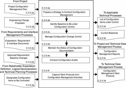
Figure C-13 - Technical Risk Management Process
C.3.5Configuration Management Process
C.3.5.2 Inputs and Sources:
a. Project configuration management plan, if any (from project).
b. ECPs (from contractors, if any, and technical teams).
c. Expectations and requirement outputs to include
stakeholder expectations, technical requirements, derived technical
requirements, system and end product specifications, requirement
documents, and interface control documents/drawings (from Requirements and
Interface Management Processes).
d.Approved requirement baseline changes, including interface
requirement changes (from Requirements Management and Interface
Management Processes).
e. Concepts of operations, enabling product strategies, logical
decomposition models, SEMP, technical plans, and other configuration items
identified in the list of CIs to be controlled (from
Stakeholder Expectation Definition, Logical Decomposition, Technical
Planning, and other technical processes as appropriate).
C.3.5.3 Outputs and Destinations:
a. List of configuration items to be placed under control (to
applicable technical processes).
b.Current
baselines (to Technical Requirements Definition, Logical
Decomposition, Design Solution Definition, and Product Implementation,
Integration, Verification, and Validation Processes.)
c. Configuration management reports (to project and Technical Data
Management Process).
d.Work products from configuration management activities (to
Technical Data Management Process).
C.3.5.4 Activities
For the WBS model in the system structure, the following
activities are typically performed:
a. Prepare a strategy to conduct configuration management for the
system products and designated work products to include: (1) documenting
how the project configuration management plan, if any, will be implemented; (2)
identifying configuration items to be put under configuration control; (3)
identifying schema of identifiers to accurately describe a configuration item
and its revisions or versions; (4) controlling changes to configuration items;
(5) maintaining and reporting disposition and implementation of change actions
to appropriate stakeholders including technical teams within the
project; (6) ensuring that products are in compliance with specifications and
configuration documentation during reviews and audits; (7) providing the
appropriate reference configuration at the start of each product-line
life-cycle phase; (8) obtaining appropriate tools for configuration management;
and (9) training appropriate technical team members and other technical
support and management personnel in the established configuration management
strategy and any configuration management procedures and tools.
b. Identify
baselines to be under configuration control to include: (1) listing
of the configuration items to control; (2) providing each configuration item
with a unique identifier; (3) identifying acceptance requirements for each
baseline identified for control; (4) identifying the owner of each
configuration item; and (5) establishing a baseline configuration for each
configuration item.
c. Manage
configuration change control to include: (1) establishing change criteria,
procedures, and responsibilities; (2) receive, record, and evaluate change
requests; (3) tracking change requests to closure; (4) obtaining appropriate
approvals before implementing a change; (5) incorporating approved changes in
appropriate configuration items; (6) releasing changed configuration items for
use; and (7) monitoring implementation to determine whether changes resulted in
unintended effects (e.g., have not compromised safety or security of
baseline product).
d.Maintain the status of configuration documentation to include: (1)
maintaining configuration item description records and records that
verify readiness of configuration items for testing, delivery, or other
related technical efforts; (2) maintaining change requests, disposition action
taken, and history of change status; (3) maintaining differences between
successive baselines; and (4) controlling access to and release of
configuration baselines.
e. Conduct configuration audits to include: (1) auditing
baselines under control to confirm that the actual work product
configuration matches the documented configuration, the configuration is in
conformance with product requirements, and records of all change actions are
complete and up to date; (2) identifying risks to the technical effort based on
incorrect documentation, implementation, or tracking of changes; (3) assessing
the integrity of the baselines; (4) confirming the completeness and correctness
of the content of configuration items with applicable requirements; (5)
confirming compliance of configuration items with applicable configuration
management standards and procedures; and (6) tracking action items to
correct anomalies from audit to closure.
f.
Capture work products from configuration
management activities to include a list of identified configuration
items; description of configuration items placed under control; change requests
and disposition of the request and rationale for the disposition; documented
changes with reason for change and change action; archive of old baselines; and
required reports on configuration management outcomes.
C.3.5.5 Process Flow Diagram
A typical process flow diagram for configuration
management is provided in Figure C-14 with inputs and their sources and the
outputs and their destinations. The activities of the configuration
management process are truncated to indicate the action and object of the
action.
Figure C-14 - Configuration Management Process
C.3.6 Technical
Data Management Process
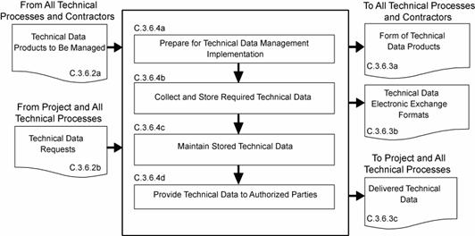
C.3.6.2 Inputs and Sources:
a. Technical data and work products to be managed (from all technical
processes and contractors).
b.Requests for technical data (from all technical processes and
project).
C.3.6.3 Outputs and Destinations:
a. Form of technical data products (to all technical processes and
contractors).
b.Technical data electronic exchange formats (to all technical
processes and contractors).
c. Delivered technical data (to project and all technical processes).
C.3.6.4 Activities
For the WBS model in the system structure, the following
activities are typically performed:
a. Prepare a strategy for the conduct of technical data management to
include: (1) determining required data content and form and electronic data
exchange interfaces in accordance with international standards or agreements;
(2) establishing a framework for technical data flow within the project
technical processes and to/from contractors; (3) designating technical
data management responsibilities and authorities regarding origination,
generation, capture, archiving, security, privacy and disposal of
technical data work products; (4) establishing the rights, obligations, and
commitments regarding the retention of, transmission of, and access to
technical data items; (5) establishing relevant data storage, transformation,
transmission, and presentation standards and conventions to be used, project or
program policy, and agreements or legislative constraints; (6) describing the
methods, tools, and metrics used during the technical effort and for
technical data management; and (7) training appropriate technical
team members and support and management personnel in the established
technical data management strategy and related procedures and tools.
b.Collect and store required technical data to include: (1) identifying
existing sources of technical data that are designated as outputs of the common
technical processes; (2) collecting and storing technical data in accordance
with the technical data management strategy and procedures; (3) recording and
distributing lessons learned; (4) performing technical data integrity checks on
collected data to confirm compliance with content and format requirements and
identifying errors in specifying or recording data; and (5) prioritizing,
reviewing, and updating technical data collection and storage procedures.
c. Maintain stored technical data to include: (1) managing the databases to
maintain proper quality and integrity of the collected and stored technical
data and to confirm that the technical data is secure and is available to those
with authority to have access; (2) performing technical data maintenance
as required; (3) preventing the stored data from being used or accessed
inappropriately; (4) maintaining the stored technical data in a manner that
protects it against foreseeable hazards such as fire, flood, earthquake, and
riots; and (5) maintaining periodic back-ups of each technical database.
d.Provide technical data to authorized parties to include: (1) maintaining
an information library or reference index to provide data available and access
instructions; (2) receiving and evaluating requests for technical data and
delivery instructions; (3) confirming that required and requested technical
data is appropriately distributed to satisfy the needs of the requesting party
and in accordance with established procedures, directives, and agreements; (4)
confirming that electronic access rules are followed before allowing access to
the database and before any data is electronically released/transferred to the
requester; and (5) provide proof of correctness, reliability, and security of
technical data provided to internal and external recipients.
C.3.6.5 Process Flow Diagram
A typical process flow diagram for technical data
management is provided in Figure C-15 with inputs and their sources and the
outputs and their destinations. The activities of the technical data
management process are truncated to indicate the action and object of the
action.
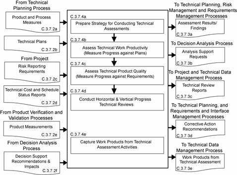
Figure C-15 - Technical Data Management Process
C.3.7 Technical
Assessment Process
C.3.7.2 Inputs and Sources:
a. Process and product measures (from Technical Planning Process).
b.Technical plans including the SEMP (from Technical Planning
Process).
c. Risk reporting requirements during technical reviews (from
project).
d.Technical cost and schedule status reports (from project).
e. Product measurements (from Product Verification and Product Validation
Processes).
f.
Decision support recommendations and impacts (from Decision
Analysis Process).
C.3.7.3 Outputs and Destinations:
,
a. Assessment results and findings including technical performance measurement estimates of measures (to Technical Planning, Technical Risk
Management and Requirements Management Processes).
b.Analysis support requests (to Decision Analysis Process).
c. Technical review reports (to project and Technical Data Management
Process).
d.Corrective action and requirement change recommendations including
corrective actions to correct out-of-tolerance TPMs (to Technical
Planning, Requirements Management, and Interface Management Processes).
e. Work products from technical assessment activities (to Technical
Data Management Process).
C.3.7.4 Activities
For the WBS model in the system structure, the following
activities are typically performed:
a. Prepare a strategy for conducting technical assessments to include:
(1) identifying the plans against which progress and achievements of the
technical effort are to be assessed; (2) establishing procedures for obtaining
cost expenditures against work planned and task completions against schedule;
(3) identifying and obtaining technical requirements against which product
development progress and achievement will be assessed and establishing the
procedures for conducting the assessments; (4) establishing events when TPMs,
estimation or measurement techniques, and rules for taking action when
out-of-tolerance conditions exist will be assessed; (5) identifying and
planning for phase-to-phase technical reviews and WBS model-to-model
vertical progress reviews, as well as establishing review entry and
success criteria, review board members, and close out procedures; (6)
establishing which technical effort work products will undergo peer review, the
team members who will perform the peer reviews, and reporting requirements; and
(7) training team members, support staff, and managers involved in
conducting technical assessment activities.
b.Assess technical work productivity (progress and achievement against
plans) to include: (1) identifying, collecting, and analyzing
process measures (e.g., earned value measurements for measuring progress
against planned cost, schedule, resource use, and technical effort tasks) and
identifying and reporting cost-effective changes to correct variances; (2)
monitoring stakeholder involvement according to the SEMP; and (3)
monitoring technical data management against plans.
c. Assess product
quality (progress and achievements against technical requirements) to include:
(1) identifying, collecting, and analyzing the degree of technical requirement
and TPM satisfaction; (2) assessing the maturity of the WBS model products
and services as applicable to the applicable product-line life-cycle phases;
(3) determining any variances from expected values of product performance and
identifying and defining cost-effective changes to correct variances.
d.Conduct technical reviews to include:
(1) identifying the type of technical reviews and each review's purpose and
objectives (see Chapter 5 for specific technical reviews that apply); (2)
determining progress toward satisfying entry criteria; (3) establishing the
makeup of the review team; (4) preparing the review presentation materials; and
(5) identifying and resolving action items resulting from the review.
e. Capture work products from the conduct of technical
assessment activities to include: (1) identifying variances resulting
from technical assessments; (2) identifying and reporting changes to correct
variances; (3) recording methods used in doing assessment activities; (4)
documenting assumptions made in arriving at the process and product
measure outcomes; and (5) reporting corrective action recommendations.
C.3.7.5 Process Flow Diagram
A typical process flow diagram for technical
assessment is provided in Figure C-16 with inputs and their sources and
the outputs and their destinations. The activities of the technical
assessment process are truncated to indicate the action and object of the
action.
Figure C-16 - Technical Assessment Process
C.3.8Decision Analysis Process
C.3.8.2 Inputs and Sources:
a. Decision need, alternatives, issues, or problems and supporting data
(from all Technical Processes).
b.Analysis support requests (from Technical Assessment Process).
C.3.8.3 Outputs and Destinations:
a. Alternative selection recommendations and impacts (to all Technical
Processes)
b.Decision support recommendations and impacts (to Technical Assessment
Process)
c. Work products of decision analysis activities (to Technical
Data Management Process).
C.3.8.4 Activities
For the WBS model in the system structure, the following
activities are typically performed:
a. Establish guidelines to determine which technical issues are subject to
a formal analysis/evaluation process to include: (1) when to use a formal
decisionmaking procedure, for example, as a result of an effectiveness
assessment, a technical trade off, a problem needing to be solved, action
needed as a response to risk exceeding the acceptable threshold,
verification or validation failure, make-buy choice, evaluating a
solution alternative, or resolving a requirements conflict; (2) what needs to
be documented; (3) who will be the decision makers and their responsibilities
and decision authorities; (4) how decisions will be handled that do not require
a formal evaluation procedure.
b. Define the criteria for evaluating alternative solutions to include: (1)
the types of criteria to consider including the following: technology
limitations, environmental impact, safety, risks, total ownership and
life-cycle costs, and schedule impact; (2) the acceptable range and scale
of the criteria; and (3) the rank of each criterion by its importance.
c. Identify alternative solutions to address decision issues to include
alternatives for consideration in addition to those that may be provided with
the issue.
d.Select
evaluation methods and tools/techniques based on the purpose for analyzing a
decision and on the availability of the information used to support the method
and/or tool.
e. Evaluate alternative solutions with the established criteria and selected
methods to include: (1) evaluation of assumptions related to evaluation
criteria and of the evidence that supports the assumptions; and (2) evaluation
of whether uncertainty in the values for alternative solutions affects the
evaluation.
f. Select recommended solutions from the alternatives based on the
evaluation criteria to include documenting the information that justifies the
recommendations and gives the impacts of taking the recommended course of
action.
g. Report the analysis/evaluation results/findings with recommendations,
impacts, and corrective actions.
h.
Capture work products from decision analysis activities to
include: (1) decision analysis guideline generated and strategy and procedures
used; (2) analysis/ evaluation approach, criteria, and methods and tools used;
(3) analysis/evaluation results, assumptions made in arriving at
recommendations, uncertainties, and sensitivities of the recommended actions or
corrective actions; and (4) lessons learned and recommendations for improving
future decision analyses.
C.3.8.5 Process Flow Diagram
A typical process flow diagram for technical
decision analyses is provided in Figure C-17 with inputs and their sources and
the outputs and their destinations. The activities of the decision
analysis process are truncated to indicate the action and object of the action.
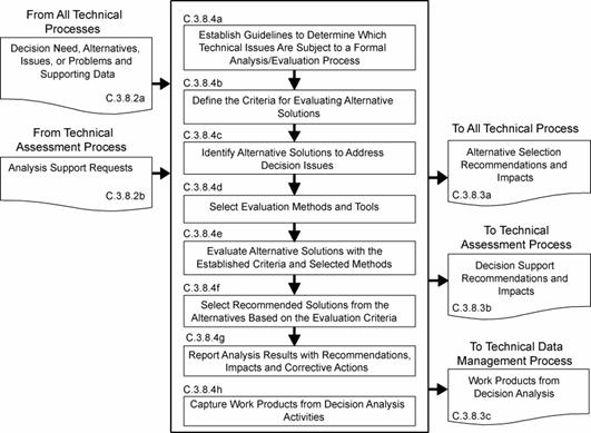
Figure C-17 - Decision Analysis Process
DISTRIBUTION:
NODIS
This Document is Obsolete and Is No Longer Used.
Check the NODIS Library to access the current version:
http://nodis3.gsfc.nasa.gov
![[NASA Logo]](../Images/nasaball.gif)