![[NASA Logo]](../Images/nasaball.gif)
| |
NASA Procedures and Guidelines |
This Document is Obsolete and Is No Longer Used.
|
|
P.1 Purpose
P.2 Applicability
P.3 Authority
P.4 References
P.5 Cancellation
1.1 NASA Maintenance Philosophy
1.2 NASA Maintenance Objectives
1.3 Center Participation
1.4 Pillars of the Maintenance Program
1.5 Facilities Maintenance Definitions
2.1 Introduction
2.2 Publications
2.3 Resources Management
2.4 Maintenance Funding Levels
2.5 Facilities Maintenance Budget
2.6 Reimbursable Services
3.1 Chapter Scope
3.2 Facilities Maintenance Functions
3.3 Management of Facilities Maintenance Program
3.4 System Concepts
3.5 Factors Affecting Facilities Maintenance Organizations
3.6 Organization and Staffing
3.7 Customer Relations
3.8 Interfaces with Other Support Organizations
3.9 Physical Plant Information
3.10 Data Gathering
3.11 Management Indicators
3.12 Management Analysis
4.1 Introduction
4.2 Purpose
4.3 Background
4.4 The Link between Planning and Execution
4.5 Content
4.6 Information Sources
4.7 Structure and Interrelationship of AWP Elements
4.8 5-year Facilities Maintenance Plan
4.9 Facilities Work Requirements
4.10 Resources
5.1 Introduction
5.2 Maintenance Execution Overview
5.3 Work Generation
5.4 Work Control Center
5.5 Work Reception and Tracking
5.6 Work Order Preparation
5.7 Work Execution
6.1 Introduction
6.2 CMMS Requirements and Usage
6.3 Automated System Interfaces
6.4 CMMS Functions
6.5 CMMS Peripheral Systems
7.1 Introduction
7.2 Philosophy
7.3 RCM Principles
7.4 Requirements Analysis
7.5 Failure
7.6 RCM Program Benefits
7.7 Impact of RCM on the Facilities Life Cycle
7.8 RCM Program Components
7.9 Other RCM Applications
8.1 Introduction
8.2 RCM - Integral to Acceptance
8.3 Acceptance Testing
8.4 Acceptance Scope
8.5 Applications
8.6 Acceptance Data Sheet
9.1 Introduction
9.2 Background
9.3 Facility Life Cycle
9.4 General Principles
9.5 National Research Council (NRC) 2- to 4-percent Guidance
9.6 Facilities Condition Assessment (FCA)
9.7 BMAR Reporting
10.1 Introduction
10.2 Facilities Maintenance Standards
10.3 Facilities Condition Standards
10.4 Work Performance Standards
10.5 Continuous Inspection
10.6 Facilities Condition Assessment (FCA)
10.7 Maintenance Work Actions
10.8 Center Appearance and Grounds Care
10.9 Maintenance Support Information (MSI)
11.1 Chapter Scope
11.2 Utilities Planning and Management
11.3 Central Utility Plant Operations and Maintenance
12.1 General
12.2 Performance-based Contracting
12.3 Outcome Specifications
12.4 Partnering
12.5 Incentives in Government Service Contracts
12.6 Quality Assurance
12.7 Credit Card Procurement
2-1 Expenditures Allocable to 2- to
4-Percent-of-CRV Standard
3-1 Whole Maintenance Universe
3-2 Basic Facilities Maintenance Program
3-3 Management Indicators
3-4 Continuous Improvement Process
3-5 Benchmarking Process Steps
4-1 Facilities Maintenance Annual Work Plan Elements
5-1 Work Request Processing
5-2 Stages in Work Generation, Control, and Performance
5-3 Sample Priority System
5-4 Work Scheduling Relationships
7-1 Reliability Centered Maintenance (RCM) Decision Logic Tree
7-2 Failure Codes
7-3 Stages of Life-Cycle Cost Commitment
9-1 Effect of Adequate and Timely Maintenance and Repairs on the Service Life of Buildings (Appendix B, resource 35)
9-2 Typical BMAR Reduction Funding Profile
10-1 Facility User Inspection
10-2 Equipment/Discrepancy Classification Form
10-3 Sample FCA Process Model
12-1 Contract Sections
12-2 Function Diagram
C-1 Sample Form: Trouble Call Ticket
C-2 Sample Form: Request for Facilities Maintenance Services
C-3 Sample Form: Facilities Maintenance Work Order
C-4 Sample Form: Facilities Maintenance Work Order Continuation Sheet
C-5 Sample Form: Facilities Maintenance Work Order Material/Equipment Requirements
C-6 Sample Form: Shop Load Plan
C-7 Sample Form: Master Schedule
C-8 Sample Form: Shop Schedule
D-1 Sample Operating Locations Drilldown Screen
D-2 Sample Operating Location Equipment History
D-3 Sample Equipment Screen
D-4 Sample Safety Plans Screen
D-5 Sample Inventory Control Screen
D-6 Sample Work Request Screen
D-7 Sample Work Order Tracking Screen
D-8 Sample Planning Screen
D-9 Sample Dispatch Screen
D-10 Sample Quick Reporting Screen
D-11 Sample Preventive Maintenance Screen
D-12 Sample Preventive Maintenance Frequency Folder
2-1 NASA Headquarters Instructions, Procedures
Guides, and Manuals
2-2 Functional Management System Codes for Facilities Maintenance
2-3 Facilities Maintenance Funding Thresholds
3-1 Facilities Descriptive Data
3-2 Collateral Equipment Descriptive Data
3-3 Work Element Percentages and Indicators
3-4 Benchmarking Code of Conduct
3-5 Sample Center Management Metrics
3-6 Example of NASA Headquarters Management Metrics
3-7 Internal Performance Indicators
3-8 External Performance Indicators
5-1 Selected Facilities Maintenance Cycles
7-1 RCM Facility Life-Cycle Implications
7-2 Reactive Maintenance Priorities
8-1 Applicable PT&I Technologies
10-1 Suggested Inspection Intervals under Routine Operations and
Average Conditions
10-2 Criticality Selection Criteria
10-3 Sample Grounds Care Performance Requirements Summary
10-4 Typical Maintenance Support Information
Chg# |
Resp Opr |
Date |
Description of Change |
1 |
O |
4/21/04 |
Deletions made of paragraphs, references, etc., as per Jennings memo dated 12/5/03. Additional administrative changes throughout to change NPG to NPR. |
a. This document establishes minimum NASA management of facilities maintenance objectives and standards in support of NASA Policy Directive (NPD) 8831.1, Management of Facilities Maintenance, and NPD 8700.1, NASA Policy for Safety and Mission Success. In addition to stressing the NASA Administrator's emphasis on the importance of strict compliance with safety regulations, practices and procedures, it requires the practice of several proactive methods for meeting those objectives and standards, including the adoption of the Reliability Centered Maintenance (RCM) philosophy and procedures (NASA Reliability Centered Maintenance Guide for Facilities and Collateral Equipment), use of Predictive Testing and Inspection (PT&I) technologies, and maximum use of fixed price, performance-based contracts coupled with good business practices that are cost effective to accomplish maintenance.
b. This document fixes commonality of facilities maintenance definitions Agencywide among the NASA Centers and Component Facilities, thereby permitting the application of uniform measures of facilities conditions; allowing meaningful, quantitative metrics in terms common throughout the Agency and the ability to statistically analyze relative variances; compiling an information database using terminology and definitions common to and recognized by commercial software products and other industrial and Government applications; and adding credibility to the NASA facilities maintenance budgeting process through standardization.
a. This NPR is applicable to NASA Headquarters, NASA Centers, and Component Facilities. A list of the location of applicable facilities is set forth in paragraph 2.5.4, POP (Budget) Submittal.
b. Because of the differences in NASA Center organizations, this NPR does not assume or require a typical facilities maintenance organization. Instead, it uses a systems approach to describe the functions that should be included in any facilities maintenance management system, regardless of its organizational structure.
42 U.S.C. 2473 (c)(1), Section 203 (c)(1) of the National Aeronautics and Space Act of 1958, as amended.
a. 48 CFR Chapter 1, Federal Acquisition Regulation (FAR).
b. 48 CFR Chapter 18, NASA FAR Supplement.
c. NPD 7330.1, Approval Authorities for Facility Projects.
d. NPD 8820.2, Design and Construction of Facilities.
e. NPD 8710.5, NASA Safety Policy for Pressure Vessels and Pressurized Systems.
f. NPD 8831.1B, Management of Facilities Maintenance.
g. NPD 8700.1, NASA Policy for Safety and Mission Success.
h. NPD 1440.6E, NASA Records Management.
i. NPR 1441.1C, Records Retention Schedules.
j. NPR 8570.1, Energy Efficiency and Water Conservation Technologies and Practices.
k. NPR 8715.3, NASA Safety Manual.
l. NPR 8800.15A, Real Estate Management Program Implementation Manual.
m. NPR 8820.2C, Facility Project Implementation Handbook.
n. FMM 9000 Series, NASA Financial Management Manual.
o. NSS/GO-1740.9, NASA Safety Standard for Lifting Devices and Equipment.
p. NSS 1740.12, NASA Safety Standard for Explosives, Propellants, and Pyrotechnics.
q. NASA RCM Guide for Facilities and Equipment Maintenance.
This revision cancels NPR 8831.2C dated March 3, 2000.
NASA's maintenance philosophy is to aggressively and proactively pursue and adopt the safest, most cost-effective, best blend of Reliability Centered Maintenance (RCM) techniques, safety procedures and other best practices to provide safe and reliable facilities to support NASA's mission.
NPD 8831.1, Management of Facilities Maintenance, states that policy for managing facilities maintenance, in support of the stated policy NASA is the following:
1.2.1. Provide maintenance and repair of facilities and collateral equipment that protects the health and safety of personnel, protects the environment, protects and preserves NASA's capabilities and capital investment, and enables mission performance by following good business practices while minimizing life-cycle facilities costs.
1.2.2. Manage and perform facilities maintenance work cost effectively and efficiently by using state-of-the-art maintenance management systems and RCM techniques. Management systems shall, as a minimum, include a standardized and meaningful annual work plan, accurate facility condition assessment techniques, and NASA-owned (NASA or contractor maintained) Computerized Maintenance Management System (CMMS) databases.
1.2.3. Use accepted standards as a guideline to assist in determining facilities maintenance funding requirements, such as the National Research Council's (NRC) recommended 2- to 4-percent of the facilities replacement value for its facilities and equipment maintenance and repair program.
1.2.4. Continuously and proactively improve technical and managerial processes to minimize life-cycle maintenance and repair costs. These include Centers designating a single point of contact to communicate and coordinate facilities maintenance and management issues with NASA Headquarters for maximum efficiency and effectiveness; benchmarking and the identification of "best practices"; preparing and adhering to annual- and 5-year maintenance plans; performing self-assessments and applying reengineering or process-improvement techniques where appropriate; applying NASA-streamlined RCM principles, as detailed in the NASA RCM Guide for Facilities and Equipment Maintenance, . in program development and improvement; implementing Predictive Testing and Inspection (PT&I) techniques, where appropriate and whenever possible; and maximizing the population of available CMMS databases to allow for competitive, fixed and fixed-unit cost pricing.
1.2.5. Provide for the lowest life-cycle costs, improve the safety, and establish initial baselines for the subsequent PT&I of facilities and equipment through the acceptance process by enforcing the construction contractor's quality control responsibilities during construction and particularly at the time of equipment acceptance.
1.2.6. Properly account for facilities' maintenance and repair expenses in accordance with the NASA Financial Management Manual - Agencywide Coding Structure - FMM Volume 9100.
1.2.7. Use performance-based contracts with clearly defined scopes to capitalize on the contractor's experience and ingenuity; to contract for results and not just best efforts; to maximize best value through the use of Fixed Pricing and Unit Cost pricing with competition; and to improve quality through contractor selection based on past performance, by measuring against prescribed, objective and measurable performance standards, and by following a formal Quality Assurance Plan.
1.3.1. Video-Conferences. NASA Center maintenance management personnel should participate in the monthly Facility Maintenance Video-Conferences. These conferences provide an opportunity to educate personnel in new tools available for use, to disseminate lessons learned Agencywide, and to facilitate the adoption of improved practices.
1.3.2. Facility Maintenance Conferences and Workshops. NASA Center civil service and support contractor maintenance management personnel should attend facility maintenance conferences and workshops. These conferences and workshops are an opportunity to exchange ideas, make contacts with other Centers' maintenance personnel, and learn new maintenance practices that can be utilized in Center programs.
1.3.3. Center Point of Contact. Each Center and Component Facility will establish a single point of contact for interfacing with the NASA Headquarters, Facilities Engineering Division's Maintenance Team concerning facilities maintenance matters.
1.4.1. Safety. Per NPD 8700.1, NASA Policy for Safety and Mission Success, it is NASA policy to "Avoid loss of life, personal injury or illness, property loss or damage, or environmental harm from any of its activities and ensure safe and healthful conditions for persons working at or visiting NASA facilities." Safety is the Agency's number one core value. Accordingly, in the operations and maintenance of a Center's facilities, the maintenance organization shall make every effort to assure that this NASA policy for safety is adhered to in all of its activities and that the procedural requirements contained in NPR 8715.3, NASA Safety Manual, are incorporated into their daily activities.
1.4.2. Maintenance Funding and Reporting. See chapter 2 of this NPR for more detailed information. As the steward of its facilities, NASA is responsible for reporting to higher authority (Office of Management and Budget (OMB) and Congress) on ways its facilities maintenance funds are spent. To make this possible, Centers shall use Functional Management System (FMS) codes to account for and report to Headquarters their facilities maintenance funding. Additionally, for accuracy and credibility, it is necessary for Centers to establish methods in their CMMS to capture all costs associated with facilities maintenance work. NASA has adopted the National Research Council's recommendation that 2- to 4-percent of the Current Replacement Value (CRV) should be targeted for only facilities maintenance and minor repair.
1.4.3. Maintenance Management Program. See chapter 3 of this NPR for more detailed information. Maintenance management consists of all aspects of defining the requirements, job planning, job execution and analysis. An effective facilities maintenance management program maximizes the useful life of the facilities and equipment, minimizes unplanned downtime, provides an improved work environment, and produces information to make Management decisions, all within a given resource level. The approach is customer oriented and mission focused. The challenge for NASA, both at Headquarters and throughout the Agency, is for continuous improvement within the available resources, as measured and monitored by meaningful and reliable Headquarters and Center performance metrics and trend analysis, and capitalizing on the very best and latest information available through benchmarking and the adoption of best practices.
1.4.4. Annual Work Plan. See chapter 4 of this NPR for more detailed information. The annual work plan provides Centers with a vehicle to display long and short range facility requirements by articulating their needs based on mission impact and the most probable facility availability outcomes under varying budget scenarios. The plan must be designed so that it can be integrated smoothly into NASA's strategic management process, afford Center Facilities Maintenance Managers and other senior managers the ability to make risk-based decisions regardless of the budget environment, and also allow Center facility maintenance organizations to pursue and measure their continuous improvement efforts. Centers should also maintain 5-year Facilities Maintenance Plans for resource planning beyond the Annual Work Plans.
1.4.5. Maintenance Execution. See chapter 5 of this NPR for more detailed information. Maintenance execution consists of work generation, work reception and tracking, work order preparation and work execution. The maintenance execution phase should be developed based on the guidance of this NPR, best practices and available resources and should be customized to most satisfactorily address the needs of each Center.
1.4.6. Computerized Maintenance Management System (CMMS). See chapter 6 of this NPR for more detailed information. Facilities maintenance managers at NASA Centers are to use modern maintenance management systems and methods to control work activities, account for resources, and to monitor and report work execution through the use of various industry standard metrics and other management indicators. All CMMS databases must remain the property of NASA, regardless of who, NASA and/or the contractor, populates and maintains them, and any applicable maintenance contracts must explicitly include language to that effect.
1.4.7. Reliability Centered Maintenance (RCM). See chapter 7 of this NPR for more detailed information. It is NASA's policy to apply RCM principles in program development and improvement. Implementing this policy emphasizes the use of RCM concepts and its supporting programs to ultimately reduce life-cycle costs of facilities and systems of varying criticality and failure impact on NASA missions. RCM is to be used as early as possible in the planning and design stages to set technical tolerances, performance criteria and PT&I standards. RCM concepts are to be used by planners, designers, equipment procurement specialists, construction managers, and Operations and Maintenance (O&M) civil service and contractor personnel and/or anyone else involved in NASA facilities planning, design, construction, equipment procurement, and maintenance and operations.
1.4.8. Reliability Centered Building and Equipment Acceptance. See chapter 8 of this NPR for more detailed information. The NASA Reliability Centered Building and Equipment Acceptance Guide focuses on reducing facility life-cycle costs (especially infant mortality costs) by integrating PT&I techniques into the construction contractor's quality control program for equipment acceptance. In today's tight budget environment for facilities operations and maintenance, it is advantageous to use the construction contractor's quality control function to perform noninvasive diagnostic tests to verify equipment condition and installation prior to the contractor's exit from the job site. The Reliability Centered Building and Equipment Acceptance Guide focuses on using PT&I technologies to test and accept new systems during equipment installation, repair or rework, and the contractor making installation modifications as necessary to meet the prescribed standards. The result is an initial database of equipment condition for the subsequent maintenance program, the avoidance of premature wear caused by latent manufacturing defects or faulty installation, better information upon which RCM decisions will be based, longer equipment life, and ultimately minimal overall facility operating costs.
1.4.9. Backlog of Maintenance and Repair (BMAR). See chapter 9 of this NPR for more detailed information. BMAR (Also known as Deferred Maintenance) has recently taken on new, higher interest in the Federal Government, particularly in the OMB and Congress. With this interest, NASA's Deferred Maintenance (DM) shall be used in benchmarking with other agencies. With increased funding cutbacks and the need to manage funding availability more efficiently, there is a renewed requirement in ensuring that NASA's DM is realistic and that any ensuing funding is spent wisely. If the DM is to be a useful tool for assessing facility condition and determining and supporting the budget requirements to bring it to a manageable level, Agencywide use of a uniform, cost-effective procedure for determining and documenting DM is required. Such a standardized procedure for calculating DM still under development and will be forthcoming.
1.4.10. Facility Condition Assessment (FCA). See chapter 10 of this NPR for more detailed information. FCA's provide NASA Centers with information to properly develop 5-year and annual work plans and priorities for facilities maintenance, repair and revitalization. Headquarters needs adequate FCA information to ensure the proper stewardship over facilities entrusted to NASA, as well as to assist Agency Senior Management and higher authorities in projecting facilities budgetary needs in conjunction with NASA meeting its mission as directed by the President and Congress. Despite their importance, formal FCA's are time-consuming and costly to perform. Maximum use of RCM procedures and PT&I techniques that monitor facility and equipment condition, and continuous inspection that incorporates historical information from the CMMS database, ongoing maintenance and repair efforts and customer and user feedback, is necessary to provide Centers with valuable FCA information that in the past had to be developed manually. This continuous inspection coupled with minimal facility condition inspections provides the FCA without the formal process.
1.4.11. Central Utility Plant Operations and Maintenance. See chapter 11 of this NPR for more detailed information. Central Utility Plant O&M is included here because of its close operational and organizational association with facilities maintenance management. The management of utility system inspection and maintenance is directed toward maintaining safety, minimizing system downtime, minimizing cost and minimizing waste. To provide safety, reliability, high quality, and economical utility services, Utilities Management must ensure that equipment and distribution systems are maintained in top working order and that distribution line losses are identified and corrected. Standard Operating Procedures (SOP) must be developed to cover routine operations, startup and shutdown, operator maintenance, preventive maintenance, and other emerging actions such as load shedding.
1.4.12. Performance-based Contracting (PBC). See chapter 12 of this NPR for more detailed information. NASA is committed to implementing the use of PBC to the maximum extent possible. Under the PBC concept, the Government contracts for specific services and outcomes, not resources. Contractor flexibility is increased, Government oversight is decreased and attention is devoted to managing performance and results and ultimate outcomes. Contractor-Government partnering is highly recommended to achieve mutually supportive goals. The PBC should encourage the use of contractor best practices and cutting edge maintenance practices used in the private sector to give NASA the best product.
1.5.1. In order to implement the policies in NPD 8831.1, Management of Facilities Maintenance, and the guidance in this document, it is necessary to fix commonality of all facilities maintenance definitions Agencywide among NASA Centers and the Centers' Component Facilities. This permits the application of uniform measures of facilities condition; allows meaningful, quantitative metrics in terms common throughout the Agency and the ability to statistically analyze variances; enables compiling an information database using terminology and definitions common to and recognized by commercial software products and other industrial and Government applications; and adds credibility to the NASA facilities maintenance budgeting process through standardization. In addition to the definitions listed in Appendix A, Centers must use the definitions, and specifically the nine facilities maintenance work elements defined in the paragraphs below to identify, classify, and analyze facilities maintenance trends, to prepare the Center's Annual Work Plan and 5-year Plan, and for all other Agencywide facilities maintenance applications:
1.5.1.1. Facility. A term used to encompass land, buildings, other structures and other real property improvements, including utility systems and collateral equipment. The term does not include operating materials, supplies, special tooling, special test equipment, and noncapitalized equipment. (See Financial Management Manual (FMM) 9255-3 for capitalization criteria for capitalized equipment.) The term "facility" is used in connection with land, buildings (facilities having the basic function to enclose usable space), structures (facilities having the basic function of a research or operational activity), and other real property improvements.
1.5.1.2. Equipment. In NASA, equipment is broken down into two categories, collateral equipment and noncollateral equipment. These are defined as follows:
a. Collateral Equipment. Encompasses building-type equipment, built-in equipment, and large, substantially affixed equipment/property, and is normally acquired and installed as part of a facility project.
(1) Building-Type Equipment. A term used in connection with facility projects to describe equipment, which is normally required to make a facility useful and operable. It is built in or affixed to the facility in such a manner that removal would impair the usefulness, safety, or environment of the facility. Such equipment includes elevators; heating, ventilating, and air conditioning systems; transformers; compressors; and other like items generally accepted as being an inherent part of a building or structure and essential to its utility. Such equipment also includes general building systems and subsystems such as electrical, plumbing, pneumatic, fire protection, and control and monitoring systems.
(2) Built-in or Large, Substantially Affixed Equipment. A term used in connection with facility projects of any type other than building-type equipment that is to be built in, affixed to, or installed in real property in such a manner that the installation cost, including special foundations or unique utilities service, or the facility restoration work required after its removal, is substantial.
b. Noncollateral Equipment. Includes all equipment other than collateral equipment. Such equipment, when acquired and used in a facility or a test apparatus, can be severed and removed after erection or installation without substantial loss of value or damage thereto or to the premises where installed. Noncollateral equipment imparts to the facility or test apparatus its particular character at the time (e.g., furniture in an office building, laboratory equipment in a laboratory, test equipment in a test stand, machine tools in a shop facility, computers in a computer facility) and is not required to make the facility useful or operable as a structure or building.
1.5.1.3. Facilities Maintenance
a. The recurring day-to-day work required to preserve facilities (buildings, structures, grounds, utility systems, and collateral equipment) in such a condition that they may be used for their designated purpose over an intended service life. It includes the cost of labor, materials, and parts. Maintenance minimizes or corrects wear and tear and thereby forestalls major repairs. Facilities maintenance includes Preventative Maintenance (PM), PT&I, Grounds Care, Programmed Maintenance, repair, Trouble Calls (TC) (facilities repair), Replacement of Obsolete Items, and Service Request (Not a maintenance item but is work performed by maintenance organizations). Facilities Maintenance does not include fire protection, security and custodial services, new work, or work on noncollateral equipment.
b. The elements of facilities maintenance and their Center-level dollar limitations are as defined in the following paragraphs. Centers should be prepared to report their planned and actual facilities maintenance effort by these nine elements when requested by NASA Headquarters.
(1) Preventive Maintenance. The planned, scheduled periodic inspection (including safety), adjustment, cleaning, lubrication, parts replacement, and minor repair (no larger than TC scope) of equipment and systems for which a specific operator is not assigned. PM consists of many checkpoint activities on items that, if disabled, would interfere with an essential Center operation, endanger life or property, or involve high cost or long lead time for replacement. PM is the cornerstone of any good maintenance program. A weak or nonexistent PM program could result in safety and/or health risks to employees, much more emergency work, and costly repairs. Center-level dollar limitation is any dollar amount.
(2) Predictive Testing & Inspection. Those testing and inspection activities for facility items that generally require more sophisticated means to identify maintenance requirements than in PM. For example, specialized tests are used to locate thinning of pipe walls and fractures (e.g., eddy current testing, radiographic inspections, ultrasonic testing, television cameras, or aural leak detectors); to detect roof weaknesses or wet insulation areas (e.g., infrared thermographic viewers or nuclear density devices); to identify large equipment wear problems (e.g., vibration analyzers and oil analysis for wear metals and lubricant properties); and to locate charge or heat buildup in electric equipment (e.g., infrared thermography). Center-level dollar limitation is any dollar amount.
(3) Grounds Care. Grounds Care is the maintenance of all grassy areas, shrubs, trees, sprinklers, rights-of-way and open fields, drainage ditches, swamps and water holding areas (lakes, ponds, lagoons, canals), fences, walls, grates, and other similar improvements to land that are included in the NASA Real Property Accountability System, and exterior pest and weed control. The maintenance tasks include mowing, spreading fertilizer, trimming hedges and shrubs, clearing ditches, snow removal, and related work. Included in this category is the cost of maintaining Grounds Care equipment such as mowers and tractors. Center-level dollar limitation is any dollar amount.
(4) Programmed Maintenance (PGM). Programmed Maintenance consists of those maintenance tasks whose cycle exceeds 1 year, such as painting a building every 5th year. (This category is different from PM in that if a planned cycle is missed the original planned work still remains to be accomplished, whereas in PM only the next planned cycle is accomplished instead of doing the work twice such as two lubrications, two adjustments, or two inspections.) Examples of PGM include painting, roof maintenance (flood coat, flashing, patching, incidental repair by replacement), road and parking lot maintenance (overlays, seal coating, and patching), utility system maintenance (pigging of constricted lines), and similar functions. Center-level dollar limitation is any dollar amount.
(5) Repair. That facility work required to restore a facility or component thereof, including collateral equipment, to a condition substantially equivalent to its originally intended and designed capacity, efficiency or capability. It includes the substantially equivalent replacements of utility systems and collateral equipment necessitated by incipient or actual breakdown. Center-level dollar limitation is any dollar amount not to exceed $500,000.
(6) Trouble Calls (TC). TC's (subset of repair) are generally called in by telephone or submitted electronically by occupants of a facility (or facility managers or maintenance workers). Where the calls are for nonfacility work (not of a facility maintenance or repair nature) the call must be coded so that it is not included with TC's included in funding level calculations. Examples of nonfacility work are interior pest control and janitorial work such as cleaning up a spill or cleaning carpets. TC's are composed of two types of work as follows:
(i) Routine Calls. Routine calls are minor facility problems that are too small to be estimated (usually less than about 20 workhours or $2,000) and are generally responded to by grouping according to craft and location. Center-level dollar limitation is any dollar amount not to exceed $500,000.
(ii) Emergency calls. Emergency calls require immediate action to eliminate hazards to personnel or equipment, to prevent loss of or damage to Center property, or to restore essential services that have been disrupted. Emergency work is usually a response-type work effort, often initially worked by TC technicians. Due to its nature, emergency work is not restricted to a level of effort such as Routine Calls (although in many cases it falls within the workhour and/or dollar limit of routine calls). Center-level dollar limitation is any dollar amount not to exceed $500,000.
(7) Replacement of Obsolete Items (ROI). There are many components of a facility that should be programmed for replacement because they are becoming obsolete (no longer parts-supportable at the end of service life), do not meet electrical or building codes, or are unsafe but are still operational and would not be construed as "broken" and needing repair. Center-level dollar limitation is any dollar amount not to exceed $500,000. Examples include but are not limited to the following:
(i) Electric switchgear, breakers, and motor starters.
(ii) Elevators.
(iii) Control systems.
(iv) Boiler and central Heating, Ventilating, and Air Conditioning (HVAC) systems and controls.
(v) Fire detection systems.
(vi) Cranes and hoists.
(vii) Air conditioning systems using Chlorofluorocarbon (CFC) refrigerants.
(8) Service Requests. Service Requests are not maintenance items, but are so often performed by facilities maintenance organizations they become a part of the baseline. Service Requests are requests for facilities related work which is new in nature, and as such, should be funded by the requesting organization. Service Requests are initiated by anybody on the Center, are usually submitted on a form, often require approval by someone before any action is taken, usually are planned and estimated, materials procured, and shop personnel discretely scheduled to accomplish the work. Examples of these requests include installation of an outlet to support a new copier machine; providing a compressed air outlet to a new test bench; renovating an office; and installing special cabinetry. Center-level dollar limitation is any dollar amount not to exceed $500,000.
(9) Central Utility Plant Operations and Maintenance. This category is unique in that it includes the cost of operations in addition to maintenance costs. It should be used only to capture the costs of operating and maintaining institutional central utility plants, such as a central heating or steam plant, wastewater treatment plant, or central A/C (chiller) plant. The concept is that operators are assigned full time to operate the plant, but they perform maintenance between various operating tasks, making it almost impossible to segregate operational and maintenance costs. Therefore, the costs of the full-time operators (and their materials) are shown here. This facilities maintenance element does not include any work outside of the 5-foot line of the utility plant or "project" type work. Center-level dollar limitation is any dollar amount.
1.5.1.4. Backlog of Maintenance and Repair (BMAR). The BMAR also known as "Deferred Maintenance" is the unfunded facilities maintenance work required to bring facilities and collateral equipment to a condition that meets acceptable facilities maintenance standards. The key word is "unfunded." If resources are or will be available to do the work during the current year, the work is considered to be scheduled and is not part of the backlog.
This chapter discusses resources management as it relates to facilities maintenance. It covers NASA directives, policy, resources management requirements, maintenance funding levels, the Program Operating Plan (POP), and reimbursable funds.
Table 2-1 lists NASA Headquarters publications that apply to facilities maintenance resources management.
|
Although Centers manage their resources in various ways, there are requirements that create similarities among all Centers. The following are the primary ones:
2.3.1. Facilities Maintenance Cost Account Codes. NASA Headquarters must report to OMB and to the Congress on how NASA spends its facilities maintenance funds. FMS codes have been established to do this. They are defined in the NASA Financial Management Manual - Agencywide Coding Structure (FMM 9120, Part VI, Fiscal and Statistical Coding, Section 9121-52A, Coding for Functional Management Functions). Centers will use the FMS codes in the NASA Financial Management Manual (A partial listing is shown in Table 2-2) for accounting and reporting to NASA Headquarters on facilities maintenance funds. In addition to utilizing the FMS codes, Centers must establish methods in their CMMS to capture all of the costs associated with each of the nine facilities maintenance work elements listed in paragraph 1.5.1.3(b) in order to manage and analyze their facilities maintenance programs.
|
2.3.2. Fund Sources. FMM 9100 defines the standard fund sources. The possible fund sources are listed in FMM 9100, Section 9121- -52A, Coding for Functional Management Functions. POP's require that budget requests be broken down by fund source.
2.3.3. Funding Thresholds. NPR 8820.2, Facility Project Implementation Handbook, specifies facility project funding sources and thresholds. Table 2-3 summarizes the facilities maintenance work type funding thresholds.
In NPD 8831.1, Management of Facilities Maintenance, NASA Headquarters recognizes the annual funding level of 2- to 4-percent-of- CRV recommended by the Federal Facilities Council (formerly the Building Research Board), National Research Council (Appendix B, resource 35), as a reasonable funding target necessary to maintain facilities in a steady-state condition. This level is recognized as an adequate standard until an independent analysis of facilities condition assessment trends indicates otherwise.
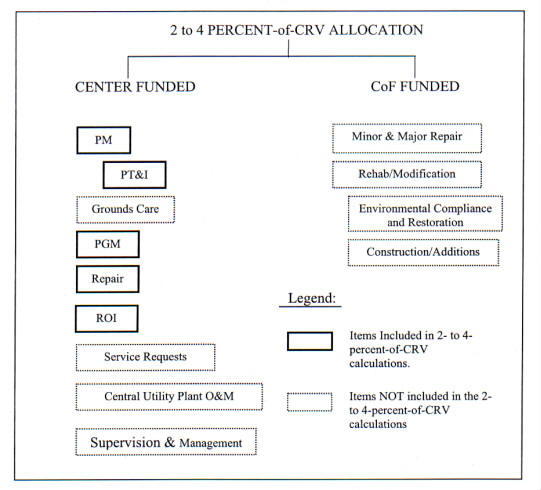
2.4.1. Funding Level Scope. Note that only Center-funded work of facilities maintenance and repairs should be included in the 2- to 4-percent-of-CRV annual funding level. Figure 2-1 identifies the facilities maintenance expenditures that are to be allocated to the 2- to 4-percent-of-CRV goal. The percentage goal does not include BMAR, Service Requests because they are for new work, grounds care, central utility plant O&M, and Nonfacilities Maintenance Work as described in paragraph 2.4.2.
2.4.2. Nonfacilities Maintenance Work
2.4.2.1. The following types of nonfacilities maintenance work, although related to facilities maintenance and sometimes performed by facilities maintenance organizations, are not counted toward the NRC-recommended 2- to 4-percent-of-CRV calculations. These types of work should be costed to their own FMS codes in the NASA Financial Management Manual.
2.4.2.2. Examples of these types of work are as follows:
a. Custodial and interior pest control.
b. Refuse collection and disposal.
c. Operations such as fire protection and security.
d. Mobile equipment operation and maintenance.
e. Environmental operations, remediation, and disposal.
FACILITIES MAINTENANCE |
CENTER |
| Preventive Maintenance. Predictive Testing & Inspection. Grounds Care. Programmed Maintenance. Repair: 1, 2, 5 - Routine Facilities Work. - Trouble Calls (Facilities Repair).1,2,5 Replacement of Obsolete Items.1,2,5 Service Requests (A New Work Requirement)1,3,5 Central Utility Plant Operations & Maintenance.4,5
| Any dollar amount Any dollar amount Any dollar amount Any dollar amount
Not to exceed $500,0005 Not to exceed $500,0005 Not to exceed $500,0005
Not to exceed $500,0005
Any dollar amount
|
Notes | |
| 1. Limitation is per project or per incident. For facilities work estimated to cost $50,000 or more, NASA Form 1509 documentation is required. | |
| 2. Costed under Routine Facilities Work functional code 20 05 04. | |
| 3. Costed under Routine Facilities Work functional code 20 05 01. | |
| 4. Costed under functional code 20 06 07. | |
| 5. All Facility Projects exceeding $500,000 must have congressional approval. |
f. Research and Development (R&D) shop support such as model fabrication.
g. Management and supervision overhead.
h. Maintenance of noncollateral equipment (NASA Equipment Management Systems (NEMS) tagged equipment).
i. Facilities alterations.
j. Facilities construction.
2.4.3. Current Replacement Value (CRV). NASA Headquarters requires updates to CRV's early each calendar year for CRV data as of December 31 of the prior year. The CRV's are to be calculated using the NASA Real Property Inventory (RPI) software program and escalating facilities and collateral equipment acquisition costs and incremental book value changes to the current year using the Engineering News Record (ENR) annual average 20-city building cost index (BCI) factors. The book value of each facility is continuously updated by the cost of any additions, modifications, or demolition of $l,000 or more. The CRV calculations are made by indexing the construction cost using the BCI value for the year of construction, indexing each change in book value using the BCI value for the year in which the change was made, and mathematically summing the results. Book values and the resulting CRV's are not changed by maintenance and repair actions. Noncollateral equipment is not included in the CRV.
POP's (budgets) are time-phased work programs expressed in terms of dollars and other resources required to accomplish NASA objectives for the budget year. They serve as a basis for developing the NASA operating budget to support apportionment requests to OMB, to distribute resource authority within NASA, and to plan for the orderly and efficient use of resources. The facilities maintenance organization's budget is an integral part of the POP. The following paragraphs provide insight into the process and how maintenance requirements are included.
2.5.1. POP (Budget) Call. A POP (budget) call is a request from NASA Headquarters to NASA Centers and Jet Propulsion Laboratory (JPL) for budget information. The call begins each year in February when the NASA Chief Financial Officer (CFO)/Comptroller requests input from the Enterprise Associate Administrators and Functional Staff Office Associate Administrators, including the Director, Facilities Engineering & Real Property Division (Code OJX), to develop the budget call to the Enterprise-related facilities. In February/March, the CFO/Comptroller integrates the budget guidance received from the Institutional Program Offices (IPO) and the Functional Staff Offices into a single POP call to the NASA Centers and JPL. Although POP (budget) guidance may vary from year to year, the basic budget content and format is relatively constant. A facilities maintenance organization is involved in the development of information to be included in response to the POP call.
2.5.2. POP Fiscal Years. Each annual POP (budget) covers a 7-year period consisting of past year, current year, and budget year defined as follows plus 4 future years:
a. Prior Year. The fiscal year immediately preceding the current year. Prior year costs are actual, not estimated.
b. Current Year. The fiscal year immediately preceding the budget year.
c. Budget Year. The fiscal year for which estimates are being submitted.
2.5.3. Requirements Development and Costing
2.5.3.1. Paragraph 2.3.1, Facilities Maintenance Cost Account Codes, requires that all Centers establish and maintain a facilities maintenance cost accounting system with all work classified. One of the uses of the classification is for budgeting. The annual budget call requests budget estimates. Thus, it is possible to prepare the budget by aggregating the actual expenditures of prior-year historical data and the current-year-to-date accounting data. The current-year-to-date figures can then be extrapolated to the full current year using the current-year . Annual Work Plan (AWP). The budget year requirements can then be projected by comparing the prior and current-year work requirements with the budget year from the 5-year Facilities Maintenance Plan and adjusting the estimates using the standard inflation factors supplied by NASA Headquarters. Through this process, information is available for preparing the budget documentation for submittal.
2.5.3.2. In accordance with the requirements of paragraph 2.4, Maintenance Funding Levels, Centers should, as a goal, work toward a budget for facilities maintenance and repair of 2- to 4-percent-of-CRV funding. Figure 2-1 identifies the facilities maintenance expenditures that are to be allocated to the 2- to 4-percent-of-CRV goal. Per paragraph 2.4.1, Funding Level Scope, the 2- to 4-percent does not include BMAR, Service Requests, grounds care, central utility plant O&M, and Nonfacilities Maintenance Work as described in paragraph 2.4.2, Nonfacilities Maintenance Work.
2.5.3.3. Because estimated funding requirements are prepared 14 to 19 months in advance of the budget year, many things can occur to change the budget estimates before POP's are executed. The following are some examples:
a. Congressional decisions reflected in the final authorization and appropriations acts.
b. Changes in the Center resource requirements (possibly due to emergency conditions).
c. Restraints imposed by NASA Headquarters.
2.5.4. POP (Budget) Submittal
The Centers and JPL submit their response to the POP requests to the IPO - Associate Administrators for Space Flight (Code M), Aerospace Technology (Code R), Space Science (Code S), and Earth Science (Code Y) - to which they are assigned. The facilities are assigned to Codes M, R, S, and Y as follows:
2.5.4.1. Code M
a. Johnson Space Center (JSC)
(1) Downey
(2) Palmdale
(3) White Sands Test Facility (WSTF)
(4) Space Network Ground Terminals, White Sands
(5) Reserved.
(a) Reserved.
(b) Reserved.
b. Kennedy Space Center (KSC)
c. Marshall Space Flight Center (MSFC)
(1) Michoud Assembly Facility (MAF)
(2) Santa Susana Field Laboratory (SSFL)
(3) Thiokol, Wasatch Division (THKL)
d. Stennis Space Center (SSC)
e. Reserved.
(1) Reserved.
(2) Reserved.
(3) Reserved.
2.5.4.2. Code R
a. Ames Research Center (ARC)
b. Dryden Flight Research Center (DFRC)
c. Langley Research Center (LaRC)
d. Glenn Research Center (GRC)
(1) Plum Brook Station (PBS)
2.5.4.3. Code S
a. Jet Propulsion Laboratory (JPL) - (A NASA-owned but contractor-operated facility)
(1) Table Mountain Observatory
2.5.4.4. Code Y
a. Goddard Space Flight Center (GSFC)
(1) Wallops Flight Facility (WFF)
(2) National Scientific Balloon Facility (NSBF)
Many Center's facilities maintenance organizations perform work on facilities occupied by agencies other than NASA for which the cost is reimbursed by the occupying agencies. They also perform nonfacilities maintenance work that should be reimbursed by the requesting customers. For specific information on policies and procedures for obtaining reimbursement related to NASA facilities occupied by another Agency see FMM 9090. This reimbursable work is not included in the annual facilities maintenance budget that the Centers submit to NASA Headquarters. However, reimbursable work should be included in the Center AWP's. The POP's and the AWP's address the total facilities maintenance workload, regardless of fund source.
2.6.1. Types of Reimbursable Services
2.6.1.1. Customer Requested Work. Centers should perform the following types of work with funds provided by the customer requesting the work, so as not to impact the limited funds available for facilities maintenance.
a. Construction, addition, and modification work below the $500,000 Construction of Facilities (CoF) threshold.
b. Service Request work.
c. Nonfacilities maintenance work (see paragraph 2.4.2, Nonfacilities Maintenance Work).
2.6.1.2. Tenant and other Occupying Agencies Services. The Centers provide three basic types of services to tenants and other occupying agencies on a reimbursable basis. These services are described in the following paragraphs:
a. Occupancy Services. Occupancy services are essential, Center-wide support services. Services such as facilities maintenance and janitorial services are a function of the square footage of the buildings occupied. Other services may be related to the number of personnel resident at the Center. Typically, the rate for occupancy services should be constant during each fiscal year to allow Center customers to budget for the services. The interagency agreements should state when the rates are scheduled to change.
b. Demand Services. Demand services provide technical support or specific deliverable products not available within the capabilities of the customer. Typically, demand services are specifically requested by the user and are user unique. Each demand service is separately priced; if possible, the unit price should be constant during each fiscal year to allow Center customers to estimate their fund requirements and to budget for the funds. Demand services are often requested in writing and are classified by specific functional area. The following are examples of demand services:
(1) Service Requests.
(2) Engineering design services.
(3) Construction projects.
(4) Heavy equipment services.
c. Other Services. Other services are those paid directly by the customer at the time of use, such as food services, or billed periodically based on use, such as metered utilities. Few, if any, facilities maintenance services are billed at the time of use.
2.6.2. Cost Allocation. The determination of reimbursable costs should be based on the concept of full cost sharing. This concept provides for common cost sharing of services. Therefore, the costs charged to each tenant should directly reflect the tenant's proportion of the total cost to NASA for the services.
2.6.2.1. Occupancy Services
a. The per-unit rates charged for occupancy services should be the same for all occupants, both tenants and NASA activities, for like services. The annual charges should be computed from prior-year costs with inflationary and expected use-change adjustments. Occupancy services are usually provided by the facilities maintenance organization or by facilities support services contractors.
b. Occupancy services are separated into those applicable to the employee population and those applicable to the floor space occupied. These costs are calculated generally as follows:
(1) Population. A projected fiscal year total of all civil service and contractor employees is developed for each occupying organization. The total portion of the shared cost associated with personnel is divided by the total of all Center personnel. The result is the fiscal year per-person rate, which is applied to each occupant.
(2) Floor Space. The square footage should be summed for each occupant by the type of space occupied as per the following example:
(i) Type I - Air-conditioned offices, laboratories, and technical spaces.
(ii) Type II - Nonair-conditioned shops, work areas, or technical spaces.
(iii) Type III - Nonair-conditioned warehouses and storage facilities.
c. The total shared cost associated with floor space is divided by the weighted sum of all three types of floor space to determine the Type III base rate. The Type I and II base rates are determined by multiplying the base rate by the weighting factor for each type. The square footage totals are multiplied by the respective rates to determine the cost for each occupant. The weighting factors are determined historically from the actual cost of cleaning and maintaining each type of space.
d. Personnel and floor space costs are then added together to determine the total occupancy cost.
2.6.2.2. Demand Services. The cost to tenants for demand services is generally developed by adding a surcharge to the incremental Center costs incurred by the demand service work order. Since the surcharges are an integral part of Center operational costs and are routinely expensed by the Centers, they are not identified separately and are not shown on reimbursable work orders. The standard surcharges developed by each Center should consider the full cost-sharing concept. However, some costs are borne by NASA, such as acquisition and depreciation of shop equipment, which do not enter the standard surcharge and therefore are not reimbursed by tenants because they are within the NASA institutional budget base. Typically, monthly billings for demand services either are sent to the tenants or are charged to standing accounts.
2.6.3. Interagency Agreements. While Memoranda of Agreement (MOA) are helpful in defining Center and tenant services and responsibilities, they are vital in the case of reimbursable services. MOA's avoid misunderstandings about how rates are determined and how bills are rendered, certified, and paid by the tenant. They are critical for long-range planning and budgeting because they enable the Centers to forecast their levels of reimbursement. In the case of facilities maintenance, the accuracy of the AWP depends on the accuracy of the level and type of reimbursable work defined in MOA's and other interagency agreements.
This chapter describes the concepts for and approach to facilities maintenance management within NASA. It describes a generic facilities maintenance management system based on proven techniques. It also provides the flexibility needed at each Center for NASA's diverse, high technology mission. The purposes of this chapter are as follows:
a. To present the methodology and value of sound facilities maintenance planning.
b. To present factors for consideration while developing a facilities maintenance organizational structure.
c. To describe the functional relationships in a facilities maintenance management system.
d. To explain methods of analyzing maintenance functions and their relationship to planning and work performance.
3.1.1. Benefits of a Facilities Maintenance Management System
3.1.1.1. A facilities maintenance management system provides for integrated processes giving managers control over the maintenance of all facilities and collateral equipment from acquisition to disposal. The management system should provide at least the following:
a. Address all resources involved.
b. Accommodate all methods of work accomplishment.
c. Effectively interface and communicate with related and supporting systems ranging from work generation through work performance and evaluation.
d. Support each customer's mission.
e. Ensure communication with each customer.
f. Provide feedback information for analysis.
g. Reduce costs through effective maintenance planning.
h. Provide a system for accumulation of historical facilities maintenance data.
3.1.1.2. The goal is to optimize the employment of scarce resources (workforce, equipment, material, and funds) to maintain the facilities and collateral equipment needed to support the Center's mission in a safe and efficient manner. An effective facilities maintenance management system maximizes the useful life of facilities and equipment, ensures safety of facilities and systems, minimizes unplanned downtime, and provides an improved work environment within a given resource level. It also produces information for management decisions.
3.1.2. Functional versus Organizational Approach
3.1.2.1. Traditionally, the guidance presented in facilities maintenance procedures guides and manuals has been based on a standard organization. That approach does not recognize the diversity in mission and site conditions found among the NASA Centers. This procedures guide adopts a functional approach to facilities maintenance. The thrust is to identify those functions and processes required to provide an effective facilities maintenance program without specifying an organizational structure.
3.1.2.2. The discussion that follows covers maintenance management controls, maintenance management concepts, maintenance-related functions and processes, and other factors for consideration in establishing a facilities maintenance organization. The process for establishing the organization must accommodate Center-unique requirements and conditions.
3.1.3. Mission/Customer versus Condition Approach
3.1.3.1. Facilities maintenance normally is regarded as the total responsibility of the facilities maintenance manager who determines with what and when to accomplish maintenance based upon the physical condition of the facilities and appropriate maintenance practices. With limited resources, however, the facilities maintenance manager should work with the customer to provide quality facilities maintenance services as required to support the customer's mission. The facilities maintenance manager should coordinate with the customer in developing attainable solutions to facilities maintenance-related mission-support problems.
3.1.3.2. Facilities maintenance decisions such as whether to accomplish work now or defer it require a knowledge and understanding of the present and future need for the facility under consideration, as well as the economic and safety impact associated with those facilities. Thus, the facilities maintenance manager must maintain perspective in evaluating necessary maintenance requirements and in considering mission criticality and the need for preserving deteriorating facilities. Both mission and customer inputs are integral components of the facilities maintenance system.
3.2.1. Facilities maintenance may be described as a number of interrelated functions and processes that directly or indirectly lead to the accomplishment of facilities maintenance work. Those that are not accomplished by the facilities maintenance organization are outside the responsibility of the primary users of thes requirements. This may also be the case when the scope of the work exceeds applicable facilities maintenance funding or resource thresholds (e.g., CoF projects). However, all functions are listed to ensure that all related services are considered when establishing a facilities maintenance organization and management system.
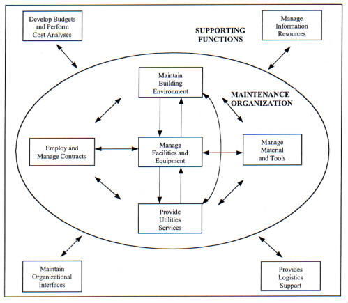
3.2.2. The following lists the major functions related to managing facilities maintenance. The relationships among the following major functions are depicted in Figure 3-1, Whole Maintenance Universe, along with the information flow and internal communication required:
a. Manage facilities and equipment.
b. Provide utilities services.
c. Employ and manage contracts.
d. Maintain building environment.
e. Manage material and tools.
f. Develop budgets and perform cost analyses.
g. Manage information resources.
h. Provide logistics support.
i. Maintain organizational interfaces.
3.2.3. The functions at the core of the whole maintenance universe reside in the Centers maintenance organization. They are the functions forming the day-to-day facilities maintenance operations and responsibilities. The maintenance organization's management is described in this chapter and its maintenance execution in Chapter 5, Facilities Maintenance Execution. The support functions in Figure 3-1 shown outside the maintenance organization are described in the following paragraphs:
3.2.3.1. Develop Budgets and Perform Cost Analyses. Although the maintenance organization performs cost analyses and develops a budget (POP) request, it is only an input to the Center and Agency's budget development. See paragraph 2.5, Facilities Maintenance Budget, for the maintenance organization's budget development.
3.2.3.2. Manage Information Resources. There are a number of information resources in other organizations supporting the maintenance organization. Personnel, cost accounting and similar staffs are required to manage a Center's maintenance operation. Of course a major function in the maintenance organization is the management of its information systems, such as its CMMS (see Chapter 6, Facilities Maintenance Management Automation).
3.2.3.3. Provide Logistics Support. A maintenance organization requires logistical support for functions such as mobile equipment (particularly large specialized items), transportation, and vehicle fuel. The maintenance organization may maintain a small warehouse for supplies and parts commonly used in its operations. Additional parts and supply support is required from the Center's logistics organization.
3.2.3.4. Maintain Organizational Interfaces. A major part of a maintenance organization's operation is its interfaces with other organizations. Working relationships and procedures must be established to assure that facilities maintenance functions are performed in an efficient and economical manner to meet Center requirements. These requirements include safety, legal, training, security, environmental, and specific requirements received in the form of Trouble Calls (TC), service requests, and similar requests.
3.3.1. Maintenance at NASA Centers is more than just repairing a leaking pipe or restoring power. It involves the coordinated effort of many talented people to ensure that facilities are in the best possible condition to support the Center's mission. To accomplish this the maintenance program must be managed to provide the maximum benefits from the available resources without waste.
3.3.2. A CMMS is an integral component of a Centers' facilities maintenance management operations. This automated system is designed to assist facilities maintenance managers in work reception, work planning, work control, work performance, work evaluation, and work reporting. This system, discussed in Chapter 6, Facilities Maintenance Management Automation, is usually linked to other database systems, such as Integrated Asset Program Management (IAPM), material management, and personnel management.
3.3.3. Figure 3-2 depicts the basic facilities maintenance management program. The program has four major aspects: Requirements Definition, Planning, Execution, and Analysis. Requirements Definition includes analyzing facilities condition assessments and the Center's mission to identify, quantify, and document Center operation and maintenance requirements. The Planning and Execution sections of the figure are discussed in Chapters 4, Annual Work Plan, and 5, Facilities Maintenance Execution. Analysis is discussed in detail in paragraphs 3.11, Management Indicators, and 3.12, Management Analysis. The following paragraphs briefly describe Figure 3-2 in a clock-wise flow starting with requirements definition:
3.3.3.1. Requirements Definition
a. Facility Inventory. The facilities inventory is the cornerstone of facilities maintenance management. It provides the detailed identification of what is inspected, operated, and maintained. Without an accurate inventory, maintainable items may not receive required maintenance, and maintenance budgeting, planning, and scheduling cannot be effective. Note that the inventory is not static; it includes continuous updates based upon facility and equipment changes.
b. Recurring Maintenance. After identification of what is inspected, operated, and maintained, a Center's Reliability Centered Maintenance program starts with identifying recurring maintenance requirements utilizing the decision logic tree shown in Figure 7-1. The requirements must be derived from analyzing the Center's mission and facilities inventory and utilizing a well-established set of local standards. The standards used in assessing facilities and determining what recurring maintenance and operations effort is needed to maintain the Center at NASA's specified quality level must include statutory, regulatory, and compliance requirements. Requirements are continually updated to include new facilities and changes based on the RCM analysis of work data provided during the acceptance process, which sets the baseline (see Chapter 8, Reliability Centered Building and Equipment Acceptance).
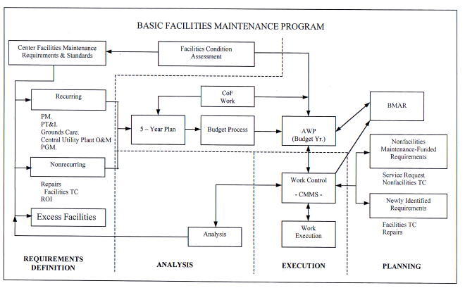
c. Nonrecurring Maintenance. Nonrecurring requirements are determined by facility condition assessments and analyzing historical data, current inventory and mission requirements. A part of nonrecurring work is facility repairs (breakdown maintenance), including facility TC's.
3.3.3.2. Planning
a. Priorities set by management based upon mission requirements are important considerations in determining what is to be accomplished and in what order. The 5-year Maintenance Plan (see paragraph 4.8, 5-year Facilities Maintenance Plan) is an invaluable reference for the budgeting process, providing the information needed to plan allocation of resources.
b. Upon receipt of the annual budget, the 5-year Maintenance Plan (including the maintenance organization's CoF work) is reviewed again, together with updated facility needs. Because resources are constrained and only a portion of the needed work may be accomplished, alternative funding is obtained where possible. The remaining required maintenance work that cannot be funded in the current fiscal year is added to the BMAR.
c. A result of the budget process and the review is the well-documented AWP that is discussed in Chapter 4, Annual Work Plan. The AWP is used to guide the majority of the day-to-day maintenance work. The AWP also serves as a baseline reference for the facilities maintenance manager when accommodating nonfacilities and newly identified facilities maintenance requirements.
d. Throughout the Planning process with the requirements, priority setting, 5-year Plan and AWP, a key and essential element is the requirements definition. In order for the planning to be effective and in concert with the goals of the Center there must be continual, two-way communication between the facilities maintenance manager and the Center staff. Proper direction will ensure that maintenance work is prioritized, planned, and performed in accordance with the Center's mission goals.
3.3.3.3. Execution
a. During execution (see Chapter 5, Facilities Maintenance Execution) the use of the AWP as a basis for work control helps to schedule work in a steady, efficient flow pattern. The nonfacilities maintenance requirements and newly identified requirements are handled by adjusting priorities and rearranging the work flow patterns as required.
b. In addition to performing maintenance and repair work, it is very important to document the work accomplished in the Center's CMMS. This documentation, as well as historical data entered in the CMMS, is essential when analyzing the work performed and in work planning.
3.3.3.4. Analysis. The Analysis section of the maintenance management program is often neglected. Proper analysis is an important management function to point out inefficiencies and ways to better execute maintenance requirements by using alternative procedures and avoiding waste. Also, analysis may identify local standards that are overly stringent for mission needs or a priority system that requires "everything to be done yesterday," thereby interrupting scheduled work unnecessarily.
In creating an organization and system to perform facilities maintenance, the concepts discussed in the following paragraphs should be applied in implementing the basic maintenance program depicted in Figure 3-2.
3.4.1. Separation of Functions. The responsibility for generating, planning and estimating, and authorizing work should be separate from the responsibility for performing work. Similarly, it is preferable for the Quality Assurance functions to be the responsibility of an autonomous organization, apart from those ordering and performing the work. This provides the system with checks and balances and free of the appearance of conflict of interest.
3.4.2. Planning and Estimating. Work should be planned and estimated in enough detail to define the resources and tasks required to perform the work and to communicate this information to everyone involved. This information must be clear to customers, approving authorities, schedulers, material managers, and craft personnel.
3.4.3. Estimating Standards. Estimating standards should be the basis for work planning and estimating to permit realistic resource allocation, scheduling, work performance, and evaluation. Several commercial, industrial, and governmental standards are available to assist in work-order estimating. Chapter 10, Facilities Maintenance Standards and Actions, provides information on estimating standards.
3.4.4. Workforce Load Planning. Work planning should provide a sufficient volume of work sufficiently in advance of the required completion date to permit balancing the facilities maintenance workload among the shops, acquiring material, arranging timely contract support, achieving priorities, and coordinating all the elements. Work should be planned on at least a quarterly basis.
3.4.5. Continuous Inspection. A program for the periodic inspection of facilities and collateral equipment should on a timely basis identify facilities condition, maintenance deficiencies, work required, and changing conditions. PT&I and Facilities Condition Assessment methods should be part of the continuous inspection program. Chapter 10, Facilities Maintenance Standards and Actions, provides detailed information on continuous inspection and condition assessment.
3.4.6. 5-year Facilities Maintenance Plan. Centers should develop long-range facilities maintenance plans covering both level-of-effort and specific or one-time work requirements. These plans should reflect the total maintenance requirements and their prioritization in support of Center mission needs. Such management planning requires developing and justifying resource requirements on a multiyear basis. Centers must prepare both 5-year Facilities Maintenance Plans and AWP's. Chapter 4, Annual Work Plan, provides information on both of these plans.
3.4.7. Work Grouping
a. Personnel performing TC's, small Service Requests, and small repair jobs should be organizationally separated from personnel performing large facilities maintenance projects when possible. Twenty hours of effort is a suggested upper limit on the scope of these small jobs. Assigning these small jobs to a single shop avoids interrupting the workforce devoted to PM, PT&I, PGM, and larger repair jobs. The organization of the shops or groupings within a given shop should be based on factors such as work volume, geographic proximity, availability of transportation, materials and craft mix.
b. Work grouping also allows crafts personnel to productively complete small jobs by "batching" (i.e., providing crafts personnel with multiple TC's at once, grouping work in a particular building or area, or providing transportation with commonly used tools and materials). This reduces indirect time associated with processing small jobs (such as travel time or getting tools, equipment, and materials).
3.4.8. Work Scheduling. Work should be scheduled in an orderly manner considering safety, customer requirements, time constraints, material and tool/equipment availability, priority, workforce availability, and work-site availability along with necessary equipment or utility outages.
3.4.9. Work Status. The CMMS should include reporting systems that provide facilities maintenance managers the status of all work and any significant problems so they may take timely corrective action. Chapter 6, Facilities Maintenance Management Automation, discusses the use of CMMS.
3.4.10. Quality Assurance (QA). Both Government- and contractor-performed work should be subject to inspections for quality. Quality control is the contractor's (or civil service, if applicable) program in place to ensure that the product or service meets the quality requirements of the specification or work order. Quality assurance is the Government's program that validates the product or service quality and, by extension, ensures that an effective quality control program is in place and is performing as previously approved by the Government. In performance-based contracts, written QA plans must be prepared to guide these inspections and should be an integral part of all maintenance work. See Chapter 12, Contract Support, for detailed information on Quality Assurance Plans.
3.4.11. Condition Assessment/BMAR. The continuous assessment of the condition of facilities and collateral equipment coupled with the current BMAR defines the major portion of that total maintenance required to bring facilities up to NASA safety and condition standards. When evaluated with respect to a Center's safety and its mission requirements, the BMAR is a key element in management planning, budgeting, and allocating facilities maintenance resources. This process is discussed in Chapters 9, Backlog of Maintenance and Repair, and 10, Facilities Maintenance Standards and Actions.
3.5.1. Physical Characteristics. The physical characteristics of a Center such as size, geographical distribution, climate, equipment, architectural style, and construction materials have a significant impact on the facilities maintenance organization. They directly affect the need for central shop spaces, remote job sites, travel time, special facilities maintenance equipment, and facilities maintenance standards.
3.5.2. Mission. The mission of a Center influences the facilities maintenance organization because it determines the facilities maintenance standards, the equipment mix, the workforce skill mix, work priorities, acceptable planned and unplanned down time, and resource levels. The maintenance organization must be structured to respond to the Center's mission.
3.5.3. Workforce Composition. Workforce composition is driven in large part by the Center's mission and physical characteristics. It affects the organizational structure and the division between contract and Government workforces. For example, a workforce with a large number of electricians and Air Conditioning (A/C) mechanics may dictate an organization with a separate shop for each craft. With a small workforce, these crafts may be in one shop.
3.6.1. Organizational Considerations. Organizations plan, organize, perform, control, and evaluate work. The factors in the following paragraphs are important considerations when designing the organizational structure.
3.6.1.1. Contract Versus In-house. The proportion of the facilities maintenance work accomplished by support contractors significantly impacts the organizational structure. As the contracted portion increases, the Government workforce becomes more involved in contract administration and surveillance. The optimum mix of support contractor and Government personnel should be based on local conditions and priorities and should be consistent with the guidance contained in OMB Circular A-76. The principles of sound facilities maintenance management apply equally to in-house and contract work. In NASA Centers utilizing a maintenance support contractor the contractor is a key partner in implementing and operating a successful maintenance management program.
3.6.1.2. Labor Agreements. Labor agreements may dictate certain procedures, practices, consultations, and other action. These influence the organizational structure and the Government's flexibility in making changes to the organization, work methods, or work assignments. The human resources department may provide assistance in this area.
3.6.1.3. Functional Lines. The facilities maintenance functions are vital in support of the Center's mission. Where more than one organization has responsibility for performing facilities maintenance, close coordination is necessary. The facilities maintenance organization interfaces closely, with potential for overlap, with related processes such as master planning, major facilities acquisition, and transportation and utilities management. It may be logical to organize along functional lines; however, care must be taken to ensure that lines of communication are open and maintained among all related functions and organizational elements. Senior managers should encourage communication and liaison at all levels.
3.6.2. Staffing Considerations. A number of factors will influence the staffing of a facilities maintenance organization. In cases where a PBC is utilized to perform the facilities maintenance functions, the contractor is responsible for determining the staffing and skill mix of the workforce to meet the contractual requirements. The Center human resources department may provide advice in staffing matters. The following factors apply to staffing plan development:
3.6.2.1. Workload Balance. The facilities maintenance organization staffing should match the workload characteristics. The manpower resources available in each craft should closely match the amount of work included in the AWP taking into consideration work priorities and alternative methods of accomplishment. Consider using temporary or part-time employees or one-time contracts to accomplish seasonal, surge, intermittent, or one-time work requirements.
3.6.2.2. Education and Training. The facilities maintenance organization must ensure that personnel have and maintain the skills needed to cope with changing technology to effectively carry out the facilities maintenance program. Skill requirements are identified through periodic reviews of all the organization workload. Comparing skill requirements with the assigned personnel skill inventory will identify shortages for correction through education, training, recruiting, or other action. Skill inventories and requirements identification should address all facilities maintenance program phases, including shop crafts, administrative skills, PT&I technologies, and the use of computers.
a. As an example, training plays a major role in reaching and maintaining skill levels required for an effective RCM program. The training should be both of a general nature and technology/equipment specific. Management and supervisory personnel benefit from training which presents an overview of the RCM process, its goals, and methods. Technician and engineer training should include the training on specific equipment and technologies, RCM analysis, and PT&I methods.
b. RCM training is available from professional organizations, consultants, equipment manufacturers, and vendors. The following are examples of specific areas of training and possible sources for the training:
(1) Infrared Thermography (IRT) is complex and difficult to measure and analyze. Training is available through infrared imaging system manufacturers and vendors.
(2) Vibration monitoring and analysis training is available from equipment vendors. The Vibration Institute has published certification guidelines.
(3) Electricians, electrical technicians, and engineers should be trained in electrical PT&I techniques such as motor current signature analysis, motor circuit analysis, complex phase impedance, and insulation resistance readings and analysis. Equipment manufacturers and consultants specializing in electrical testing techniques provide classroom training and seminars to teach these techniques.
3.6.2.3. Licenses, Permits, and Certifications
The license, permit, or certification requirements in the following paragraphs are applicable to Government employees and contractors. When work requiring licenses, permits, or certifications is included in a contract, the contract must clearly state that the contractor should obtain all applicable NASA, State, and/or local government, licenses, permits, or certifications before performing the work.
a. Specialized personnel and facilities often are required to have licenses, permits, or certifications. These requirements apply to central utility plant personnel and to environmentally or safety sensitive facilities. To the maximum extent possible, such licenses, permits, and certificates should be issued by the State or local government rather than by Centers to avoid administrative duplication. Centers should issue only those licenses, permits, and certificates that are NASA-unique and, therefore, not available through other existing regulatory organizations. Detailed training and certifications requirements may be found in specific safety standards, e.g., NSS/GO-1740.9, NASA Safety Standard for Lifting Devices and Equipment, or NSS 1740.12, NASA Safety Standard for Explosives, Propellants, and Pyrotechnics. Additional hazardous operation safety certification requirements may be designated by each Center safety official or designee, but must include the minimum as listed in Chapter 4 of NPR 8715.3, NASA Safety Manual.
b. Central utility plant operators, such as at water treatment plants, boiler plants, and wastewater treatment plants, should be licensed by applicable State and local governments. Also, when required by State or local governments, permits for such things as incinerators, licenses for other facilities maintenance-related operations such as pest control and herbicide applicators, and certificates for equipment such as pressure vessels, lifting devices, and elevators must be obtained.
Everyone who works at or uses Center facilities is a customer of the facilities maintenance organization. Some are direct customers, requesting and receiving specific services such as TC's or Service Requests. Others are indirect customers, using the facilities and collateral equipment such as HVAC systems maintained by the facilities maintenance organization. Facilities maintenance, which provides institutional , as well as program support, plays a major role in keeping these customers satisfied. This does not occur automatically. Customer relations should be a primary consideration in all facilities maintenance decisions. Facilities maintenance may be the key factor in developing and maintaining the professional reputation of Center institutional managers.
3.7.1. Communication
3.7.1.1. The facilities maintenance organization cannot operate effectively without open communication. Communication is extremely important within the organization to ensure coordination of competing resources. Communication with customers and other Center entities is absolutely necessary to ensure that the correct work is accomplished at the correct time and within allocated resources. Communications between the maintenance organization and their customers must be an integral part of the CMMS. The system should provide for customer access to submit requirements and for the customer to obtain current status of their request from submittal through completion. Day-to-day communications may also utilize other Center electronic means, including e-mail and home page access. Facilities maintenance personnel must be alert to the following barriers to communication:
a. Cryptic, incomplete work requests.
b. Misinterpreting the scope of work specified as "the supervisor wants".
c. Customers' misinterpreting technical answers to their questions on project status.
d. Differing understandings of mission needs.
3.7.1.2. Two-way communication must be encouraged, with the customer articulating customer desires and the maintenance organization providing constructive and continuous feedback through the CMMS or other electronic systems, including e-mail, where possible. This may provide an early warning of changes in workload and identify potential problems. It facilitates orderly workload planning by the facilities maintenance organization and its customers. This is particularly important during periods of limited funding because the maintenance organization often may help a customer translate desires into realistic facilities requirements, thereby obtaining an optimum solution or at least an adequate solution within the resources available. A well-informed maintenance organization and a "maintenance informed" Center is in a much better position to produce necessary results within available resources.
3.7.1.3. The reputation of the facilities maintenance organization is built as much on perception as on performance. A positive image of the facilities maintenance organization is created by proactive communications; i.e., keeping the customer informed about the status of the work, responding quickly to the requests, informing the customer in advance about the cost of the work, and reflecting the costs accurately in reimbursable billings and reports. The maintenance organization should have a customer liaison representative to work with each customer organization. The customer liaison should participate in the development of Memoranda of Agreement (MOA), AWP's, funding plans, and in the day-to-day support of the customer. However, every member of the facilities maintenance organization is an ambassador for the organization and should be sensitive to each customer's needs and perceptions.
3.7.1.4. The maintenance organization must have open communications with personnel and organizations such as the following:
a. Customers.
b. Health and safety.
c. Environmental office and agencies.
d. Engineering.
e. Mission personnel.
f. Center planners.
g. Support contractors.
h. Resource management personnel.
i. Local, State, and Federal regulatory agencies.
j. Headquarters NASA administrative and support offices.
3.7.2. Funding Sources. The facilities maintenance organization may find that a significant portion of its work is customer funded. This is especially the case with Service Requests and work directly supporting R&D programs. In establishing the organizational structure, the variability, time phasing, and duration of customer-funded work should be considered. Provision should be made for estimating and managing customer-funded work. Where the level of customer-funded work is variable or cyclical, use of contracts or temporary workers may be desirable to accommodate peaks and valleys in the workload.
3.7.3. Customer Mission. Customer relations should facilitate accomplishing the specific job that the customer requested. It includes understanding the customer's mission requirements and using this understanding to communicate with the customer and guide the customer's expectations. Thus, the facilities maintenance organization should understand the mission of each of its customers. This understanding will lead to better resource allocation decisions, enable the organization to meet each customer's needs, and improve the facilities maintenance organization's credibility by meeting real needs within the time and other resources available. Actually, the facilities maintenance organizations real mission is to support the Center mission utilizing the most cost-effective means available.
3.7.4. Memoranda of Agreement (MOA)
3.7.4.1. MOA's and other formalized agreements spell out support agreements between organizations and agencies. MOA's may cover agreements between the facilities maintenance organization and other Center departments, other Federal agencies, or local governments. Typically, MOA's outline details of services provided and funding responsibilities. It is possible for a Center to be both a receiver of services from, and a provider of services to, another organization. These services may be provided on a reimbursable or nonreimbursable basis. Examples include provision of utilities, shared use of operational facilities such as runways, provision of fire protection services, and maintenance of special facilities such as aviation fueling systems. Examples of MOA's from other Federal agencies are training and support from the Navy and General Services Administration (GSA).
3.7.4.2. MOA's may offer significant advantages through better use of facilities and avoid duplication of effort. The facilities maintenance organization should be alert for opportunities to use MOA's. Where services are available under an MOA, the facilities maintenance organization would not need to dedicate organizational resources to provide the service. The increased scope of the combined service may make it possible for the provider to perform the service at a reduced unit cost to all customers by realizing economies of scale. Properly managed, the increased scope also may provide flexibility and increased capability during a time of emergency. An assessment of the impact of MOA's should be made while developing AWP's.
Facilities and equipment maintenance program effectiveness often depends on the support provided by other Center organizations. For example, the Comptroller may prepare budgets and allocate funds, the Human Resources Office may control staffing, the Procurement Office may handle requests for material, and the Administrative Office may handle reproduction and correspondence services. Responsibility for facilities planning and engineering, including major facilities and equipment acquisition, may rest with a separate organization such as Facilities Engineering. Essential services such as utilities may be purchased commercially or provided by a separate Government or host activity. The facilities maintenance organization should maintain close communication and cooperation with other supporting organizations, working together to plan and manage the workload.
3.8.1. Safety. It is NASA policy to "Avoid loss of life, personal injury or illness, property loss or damage, or environmental harm from any of its activities and ensure safe and healthful conditions for persons working at or visiting NASA facilities" (Appendix B, resource 13). To accomplish this, all individuals must act responsibly in matters of safety. The Center facilities maintenance organization is responsible for their role in safety by maintaining facilities in a safe condition and by performing tasks in a safe manner in accordance with NASA policy.
3.8.2. Environmental Compliance. Although environmental compliance is not typically one of the primary responsibilities of the Center facilities maintenance organization, virtually every facilities maintenance action has a potential impact on the environment. For this reason, facilities maintenance personnel must be knowledgeable about environmental requirements, adhere to applicable environmental rules and regulations, become involved to the limit of their responsibilities, and maintain open communication links with cognizant NASA environmental protection staff and regulatory officials. Environmental regulation compliance is a primary input item to establish standards.
3.8.3. Energy Management. The Center facilities maintenance organization is a prime participant in the Center's energy management program as developed in accordance with NPR 8570.1, Energy Efficiency and Water Conservation Techniques and Practices. The maintenance organization participates in identifying and is responsible for implementing O&M procedures and/or process improvements that are in the Center's Energy Efficiency and Water Conservation 5-year Plan. Responsible maintenance organization staff members help conduct energy audits. Analysis of the Center's Energy Management and Control Systems (EMCS) data must be included in the maintenance organization's planning to identify changes that indicate maintenance problems or imminent equipment or system breakdowns. All of this energy management program support must be integrated into the maintenance organization's AWP and 5-year Plan.
3.8.4. Contract Support
3.8.4.1. Much of the Center facilities maintenance work is performed by contract, either by separate, specific, one-time CoF contracts, specific facilities maintenance contracts (using non-CoF funds), or support services contracts. In the case of the specific, one-time contracts, the facilities maintenance organization's responsibility is limited to initial facilities maintenance and repair requirements identification, perhaps preliminary scope definition or cost estimate preparation, observing the facility's acceptance testing (as appropriate), acceptance of initial base line data, and resumption of the maintenance responsibility after the contract is complete. For facilities maintenance support services contracts, the facilities maintenance organization has a greater responsibility. It should be involved throughout the acquisition process in each of the following functions:
a. Determining the need for the contract.
b. Serving as a member of the acquisition team.
c. Drafting the acquisition schedule and milestones.
d. Preparing the needs analysis.
e. Writing the acquisition plan.
f. Writing the statement of work.
g. Assisting Procurement in determining the contract type.
h. Writing the quality assurance plan.
i. Conducting quality assurance surveillance during contract performance.
3.8.4.2. Close coordination with the cognizant procurement office is essential in obtaining quality services in a timely fashion. Additionally, emphasis should be placed on advance acquisition planning to ensure continuity of services.
a. Initially the maintenance organization must know the facility activity status in order to establish a facility's maintenance requirement. The status may range from active to abandoned with each status requiring a different level of maintenance (see paragraph 3.9.1, Facility Activity Status).
b. Information describing the facilities and collateral equipment at a Center is essential for planning facilities maintenance actions, efficiently performing facilities maintenance, documenting maintenance histories, following up maintenance performance, energy reporting, and management reporting. Without this information, neglect of essential systems is likely, leading to inefficient operation, system failure, or loss of service.
c. With the increasing use of CMMS, obtaining the information in computer readable format is strongly recommended. Chapter 6, Facilities Maintenance Management Automation, addresses CMMS requirements and usage.
d. Complete physical plant information consists of several databases distinguished by the type of information they contain. Chapter 6, Facilities Maintenance Management Automation, discusses databases from the perspective of facilities maintenance management automation. The following paragraphs examine the physical plant information databases in terms of the type of information they contain.
3.9.1. Facility Activity Status. The following paragraphs are to provide insight into facility status classifications. Each status has its own level of maintenance required ranging from full maintenance for an active facility to no maintenance for a facility with an abandoned status. For detail information on maintenance requirements for each inactive facility status see NPR 8800.15, Real Estate Management Program Implementation Manual.
a. Active facility. Any facility that has a specific and present, or near term, program or institutional requirement. Space utilization would normally be at least 50-percent and/or the usage level exceeds 50-percent of the available time for use.
b. Inactive facility. Any facility that has no specific and present, or near-term, program or institutional requirement. The inactive facility may be placed in a "Standby," "Mothballed," or "Abandoned" status. The following generally applies to all levels of inactive facilities:
(1) No personnel occupy the facility.
(2) Utilities are curtailed, other than as required for fire, security, or safety.
(3) Facility is secured to prevent unauthorized access and injury to personnel.
(4) Facility does not receive funding for renewal, or other significant improvement.
(5) Reserved.
3.9.2. Descriptive Data
a. Descriptive data is the detailed identifying information on the items to be maintained. The data falls into the following two classes:
b. Each separately identified and maintained item may be part of a hierarchy of systems and subsystems. For example, a motor may be a component of the water circulating subsystem of an A/C system in a facility.
c. Descriptive data should identify items to their related systems and subsystems. The number of hierarchical levels depends on Center requirements, but four levels of system/subsystem is the suggested minimum. For equipment, the descriptive data should include the equipment classification or grouping.
3.9.2.1. Facilities. Table 3-1 provides a listing of descriptive factors and attributes used to develop a facilities database. This list is a suggested minimum for facilities management. The items on this list are generally self-explanatory.
| Facility Number | Material |
| Facility Title | Finish |
| Location Status |
Inspection Cycle (Yrs) PGM Checklist/Guide No. |
| Facility Component (e.g., Ceiling, Door, Floor, Flashing, Wall, Drainage, Parapet) |
Estimated Design Life (years) Funding Source |
| Facility System (e.g., Exterior, Interior, Roof, Tank, Fence, Grounds) |
Construction Date Condition Code |
3.9.2.2. Collateral Equipment. Table 3-2 is a list of descriptive factors and attributes used to develop a collateral equipment database. This list is a minimum for collateral equipment maintenance management. Centers with PT&I programs will have additional equipment data elements such as location of test points.
| Inventory Number Nomenclature Location - Building Floor Room Zone Manufacturer Vendor/Supplier Model Serial Number Date Acquired |
Estimated Life Cost Size - Capacity HP Voltage Weight Current Dimensions Systems - Major System Subsystem Major Component Component |
Classification Use/User Priority Funding Source PM Cycle Identifiers PM Guide No. Inspection Identifiers Condition Code |
3.9.3. Drawings
3.9.3.1. Drawings and other graphic data are a significant portion of the physical plant information, especially for buildings, structures, utilities systems, real estate, and land improvements. They also may be a significant portion of the available information for equipment in the form of shop drawings, schematics, photographs, and assembly drawings. Drawings may exist in many forms, including paper, photographs (such as microfilm, microfiche, and aperture cards), video images, and computerized data. Computerized forms include Computer Aided Design and Drafting (CADD), Geographic Information Systems (GIS) or vector based drawings. Drawings may be linked to work orders through a CMMS database.
3.9.3.2. Significant challenges in drawing management include keeping drawings up to date, maintaining an indexed library of drawings, and maintaining a linkage between the drawings and the systems they represent. To the maximum extent possible, Centers should require all drawings for new or modified facilities and equipment to be delivered to the Government in computer readable and revisable form. However, the wholesale conversion of existing drawings to computerized form may not be practical. All drawings should be filed and retained in accordance with guidance provided in NPR1441.1, Records Retention Schedules.
It is necessary to gather facilities and collateral equipment data to support the facilities maintenance program.
3.10.1. Existing Databases
3.10.1.1. Existing databases maintained by the Center provide a starting point for developing an inventory of maintainable facilities and collateral equipment items. However, databases developed for other purposes, such as financial accounting, will not identify all maintainable items, systems, subsystems, and components. Further, they may include items not relevant for facilities maintenance management purposes. Using these databases as a starting point requires screening entries for inclusion in the facilities maintenance database. Where a unified Center database exists, this might take the form of flagging records as part of the facilities maintenance management program. Where the existing data is in a computerized database, it also may be possible to arrange for electronic transfer of portions of the data. This may simplify loading the data into the facilities maintenance management database. Potential existing databases include the NASA Real Property Data System and Center-unique industrial plant, personal, and minor property or collateral equipment inventory systems.
3.10.1.2. Creation of separate databases with common data elements carries the risk of having conflicting data. If separate databases are created, a methodology must be developed and implemented to update the data from one database to the others to avoid inconsistencies.
3.10.2. Physical Inventory. A physical inventory may be necessary to verify the data imported from other databases and to gather supplemental information to identify maintainable items and their associated systems, subsystems, and components not previously inventoried. Identification tags placed on collateral equipment during the inventory will help to ensure that all maintainable collateral equipment is picked up for entry into the database. Using identification tags also helps to avoid duplication.
3.10.2.1. In-house. It is possible to perform a complete physical inventory using in-house forces as part of the continuous inspection and PM programs. However, this effort may take a long time and could result in the diversion of a significant portion of the facilities maintenance workforce, thereby adversely impacting routine facilities maintenance.
3.10.2.2. Contract. Contracting for the inventory is an effective method of obtaining the data. The contract may be a separate action, in conjunction with a comprehensive condition assessment, or it may be part of the development of Maintenance Support Information (MSI). For more information see paragraph 10.9, Maintenance Support Information (MSI).
3.10.2.3. Inventory Maintenance. Once developed, the facilities and collateral equipment inventory requires continuous updating to reflect additions, deletions, or changes to the physical plant. Normally, this effort is part of the continuing inspection program.
3.10.2.4. Identification Tags. Equipment identification tags should be clearly visible. Using permanent, machine-readable tags such as preprinted bar code labels eases maintenance and inventory automation and reduces the potential for data entry errors.
3.10.3. User Information. Equipment users or custodians also are a source of inventory information as they receive new equipment or determine that equipment they already have requires maintenance. The initial identification typically will take the form of a request for equipment installation or maintenance. It may also be a response to a call for inventory assistance from the facilities maintenance organization. In either case the information provided may not be enough for facilities maintenance management purposes. A field investigation may be necessary to obtain all of the maintenance information.
a. Paragraph 3.11.1, Work Element Relationships, discusses the total facilities maintenance effort and relationships among the individual work element efforts. However, there are a number of other relationships typically used in the facilities maintenance community for indicating the effectiveness of the facilities maintenance operation and for comparing current performance with goals and objectives. These relationships are called management indicators, performance measures, or simply "metrics". Three ratios/indicators/metrics are shown in Table 3-3 as examples.
b. As shown in Figure 3-3, management indicators may be expressed as words (such as "outstanding" or "excellent") or numbers (metrics). Current management theory holds that one cannot manage an operation effectively unless one may measure it. Metrics are preferable to word descriptions because they may be trended more easily. Also, they tend to be more precise and objective than words. Regardless of what metrics are used by individual Centers, some system of measurement is vital to the process of continuous improvement.
c. It is NASA policy to continuously improve technical and managerial processes in order to minimize life-cycle maintenance and repair costs. One process to use is benchmarking. Using benchmarking and its related metrics Center facilities maintenance managers may evaluate maintenance performance, compare performance against maintenance standards and identify trends. This process will help managers in identifying and implementing "best practices" and provide a base for performance projections that may be used in preparing the AWP and the Center's 5-year plan.
d. The following paragraphs provide a general definition of a metric, its components, and its attributes. They also discuss the role metrics play in the continuous improvement processes and present examples of metrics used by facilities maintenance organizations.
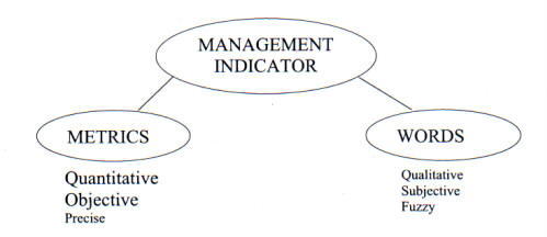 |
3.11.1. Work Element Relationships
3.11.1.1. There are relationships among the facilities maintenance work elements that indicate the strengths and weaknesses of a facilities maintenance program. Table 3-3 shows typical ranges of effort for the principal work elements at a large physical plant of diverse age and complexity.
3.11.1.2. The percentages in Table 3-3 apply to the total facilities maintenance effort. The percentage ranges are guides only. For example, if repairs exceed 20-percent by a significant amount, it may indicate that more effort must be put into PM, PT&I, and PGM. Likewise, if TC's exceed 10-percent, it may indicate that PM and PT&I effort should be increased. The greatest effort, 50- to 60-percent, should be applied to PM, PT&I and PGM. The limit on Service Request work is suggested only because of the potential for a large amount of Service Request work to detract from the maintenance effort.
3.11.1.3. The ranges in Table 3-3 are recommended as a basis for self-evaluation until each Center accumulates sufficient data to reflect its unique situation. Thereafter, analysis should be based on the relationships appropriate to the Center.
3.11.1.4. Two of the work elements do not appear in Table 3-3: Central Utility Plant Maintenance and Operations and Grounds Care. Both depend on local circumstances and vary too widely to estimate a meaningful range.
Also, there are useful ratios that may be used to assess the quality of the facilities maintenance program. These are shown in Table 3-3. Trends in these three ratios indicate facilities maintenance performance. While absolute values cannot be assigned to these ratios, facilities maintenance managers should track the ratios and strive to maintain a downward trend.
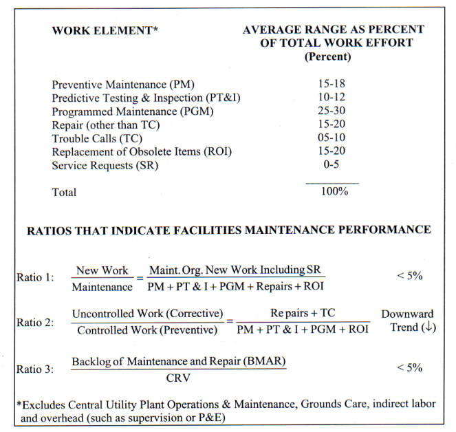
|
3.11.1.6. In the case of Ratio 1, the amount of CoF (construction and additions) and SR, both new work, is not controlled by the facilities maintenance organization. However, if the ratio is high and increasing, plant degradation may result. New work increases the CRV and the maintenance workload. Funds should increase proportionately to maintain the desired 2- to 4-percent-of-CRV funding level.
3.11.1.7. With respect to Ratio 2, the numerator may be controlled only within narrow limits. Also, the numerator is oriented toward correcting things that are broken. The opposite is true for the denominator. Management decides how much effort to expend on the denominator, which is preventive in nature because it minimizes future failures. There is an inverse correlation and a multiplier effect between the denominator and the numerator. As the denominator decreases, the numerator usually increases much faster. For example, failure to perform PM on a piece of equipment or system usually results in much more costly repair later on. A small change in the denominator, over time, causes a much larger opposite change in the numerator.
3.11.1.8. For Ratio 3, the trend should always be downward, toward the NASA goal of reducing the backlog to a manageable level.
3.11.1.9. As a general rule, the percent of work authorized by work order should increase, the percent of scheduled work should increase, and the percent of unscheduled work should decrease.
3.11.2. Metrics Definition
3.11.2.1. Metrics are meaningful measures. For a measure to be meaningful, it must present data that encourages the right action. The data must be customer oriented and be related to and support one or more organizational objectives. Metrics foster process understanding and motivate action to continually improve the way a process is performed. This is what sets metrics apart from measurement. Measurement does not necessarily result in process improvement. Effective metrics always will. Projecting this improvement, metrics may be used in preparing a Center's AWP and 5-year Plan.
3.11.2.2. A more useful definition for managers is that a metric is a measurement that is made repeatedly at prescribed intervals and that provides vital information to management about trends in the performance of a process or activity or in the use of a resource.
3.11.2.3. Each metric consists of a descriptor and a benchmark. A descriptor is a word description of the units used in the metric. A benchmark is a numerical value of the metric, or the limits within which the metric is to be kept, that management selects as the goal against which the measured value of the metric is compared. For example, a typical metric is the ratio of emergency work to total facilities maintenance work expressed as a percentage and shown in the following equation:
Emergency Work (hr) x 100 = %
Total Maintenance (hr)
3.11.2.4. The emergency work and total maintenance work are the descriptors, the units of which are hours. In the example, 2-percent is the goal, or benchmark.
3.11.3. Metrics Attributes
3.11.3.1. Metrics have common attributes that should be considered when they are being developed. A good metric has many of the following attributes:
a. It is customer oriented.
b. It is linked to a goal or objective.
c. It is process/action oriented.
d. It distinguishes good from bad or desirable from undesirable results.
e. It is derived from data that is readily collectable.
f. It is trendable.
g. It is repeatable.
h. It is simple.
i. It expresses realistic/achievable goals.
3.11.3.2. Customer orientation is important because the ultimate success of facilities maintenance services is partly dependent on how they are perceived by the customer. A metric should be action oriented, which means that the organization must have the capability to change the metric parameters. Just as one cannot manage effectively what one cannot measure, there is no need to measure what one cannot control. A metric should distinguish good from bad, which again is based on a standard or goal; i.e., movement toward the goal is good, and conversely, movement away from the goal is bad. The data for the metric should be collectable, preferably already contained within the accounting system or the CMMS. A metric must be trendable so that successive readings may be compared with meaningful results. It should be simple, so that those who use it, carry it out, or are affected by it may understand it. Finally, the metric must be realistic. If it is clearly not achievable, workers will not strive to achieve it.
3.11.4. Metrics Role in Continuous Improvement
3.11.4.1. Two organizations that promote the use of metrics for continual improvement are the American Productivity and Quality Council (APQC) and the American Society for Quality (ASQ). While the APQC's emphasis is on benchmarking, the ASQ promotes customer satisfaction as the means to achieve continuous improvement.
3.11.4.2.
3.11.4.3. When the metric is implemented, management should establish the baseline, i.e., where the organization is with respect to the benchmark. Preferably, this information is known, at least approximately, and used when setting the goal (benchmark). Then management must develop a system to measure and report the descriptor condition regularly over uniform periods of time (e.g., daily, weekly, monthly). The measured value is compared with the benchmark to identify the gap between the two. Management then acts to close the gap. After several iterations, it may become apparent that either the descriptor is not appropriate or the benchmark is unrealistic. If this is the case, the metric should be revised and a new baseline determined. If the original metric is both suitable and realistic, the measurement cycle should be repeated with the gap between the benchmark and the measured value becoming progressively smaller. In this situation, true continuous improvement is occurring.
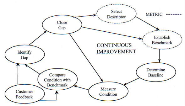 |
3.11.5. Benchmarking. One of the best methods for achieving continuous facilities maintenance improvement is using metrics with benchmarking. Benchmarking is the process of continuously identifying, measuring, and comparing one's processes, products, or services against those of recognized leaders in order to achieve superior performance. The benchmarking process steps are shown in Figure 3-5.
3.11.5.1. Objectives. The objectives of benchmarking are as follows:
a. Accelerate the change process.
b. Achieve both incremental and breakthrough improvements.
c. Achieve greater customer satisfaction.
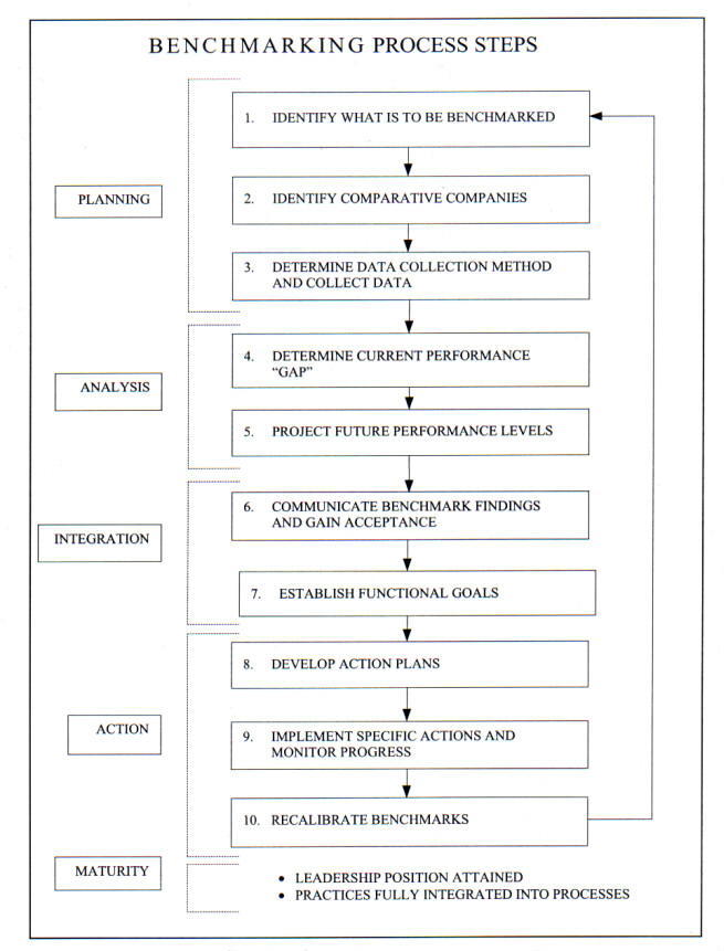 |
d. Learn from the best to avoid reinventing (applying lessons learned).
e. Apply best practices utilizing the latest feasible technology.
3.11.5.2. Types of Benchmarking
a. Internal. A comparison of internal operations; for example, within a Center or NASA-wide.
b. Competitive. A competitor-to-competitor functional comparison.
c. Functional. A comparison of similar functions within NASA Centers or with industry leaders.
d. Generic. A comparison of functions or processes that are the same regardless of Center or industry.
3.11.5.3. Approaches To Benchmarking. The NASA approach found to be successful has been generic benchmarking using the hybrid approach. Benchmarking approaches are as follows:
a. Centralized. Managed by a single corporate entity; e.g., by NASA Headquarters.
b. Decentralized. Managed at the local level; e.g., by individual Centers.
c. Hybrid. A combination of the centralized and decentralized approaches.
3.11.5.4. Benchmarking Procedures. Referring to the general steps shown in Figure 3-5, Benchmarking Process Steps, the benchmarking process should proceed as follows:
a. Develop a specific list of the functions that the maintenance organization does well and that may be offered to benchmarking partners as best practices.
b. Develop a specific list of the functions about which the maintenance organization is concerned; i.e., those that need improvement.
c. Identify specific companies, professional facilities maintenance associations, and facilities maintenance-related publications known to excel in the specific areas of concern.
d. Develop a questionnaire to obtain specific data about the functions the maintenance organization wishes to benchmark (concerns) and send it to the prospective benchmarking partners identified in paragraph 3.11.5.4.c.
e. Analyze the questionnaire responses to identify the best potential benchmarking partners.
f. Offer to benchmark with one or more of the organizations identified in paragraph 3.11.5.4.c. These organizations are the best potential benchmarking partners.
g. After benchmarking agreements have been reached, exchange lists of lessons learned, best practices, and concerns.
h. Suggest that the benchmarking partner select topics from the organization's lessons learned and best practices list for the organization to brief during the benchmarking visit. Further, ask partners to select topics from their list of concerns for the partners to brief to the organizations representatives during the benchmarking visit.
i. Exchange lists of written questions and general information such as organization charts for study at least 2 weeks prior to the benchmarking visit.
j. Arrange a mutually agreeable date for visiting the benchmarking partner.
k. Identify the points of contact for the briefings that both organizations will give so that the points of contact may coordinate and focus the presentations.
l. Develop a detailed visit agenda agreeable to both parties.
m. Observe the benchmarking code of conduct, illustrated in Table 3-4.
BENCHMARKING CODE OF CONDUCTWhen Benchmarking, you will... a. Consider legal implications. b. Be willing to give the same type of information received. c. Respect confidentiality. d. Keep information nternal. (1) Use benchmarking points of contact only. (2) Do not refer benchmarking materials to third parties without permission. (3) Understand the partner's expectations. (4) Act in accordance with the expectations. (5) Be forthright and forthcoming in discussions. (6) Follow through with commitments. |
n. Offer reciprocal visits.
o. Document visit results.
p. Distribute the documentation of the visit results to the proper internal organizational elements for evaluation.
q. Develop implementation plans.
r. Develop lessons learned.
s. Share information and benchmarking experience with other NASA organizations.
t. Follow up for continuous improvement.
3.11.5.5. Facilities Maintenance Management Indicators
a. The benchmark depends upon the Center baseline and goal or objective. More important a specific metric by itself is the recognition of its usefulness in proactively establishing patterns, trends, and correlation with other data to describe past, current and anticipated conditions. Center maintenance managers should utilize metrics on a continual bases to evaluate the effectiveness of their management.
b. A major benefit of the metric information is its evaluation over several periods to obtain trends. Metrics may be maintained visually through the use of graphs, bar charts, or other methods. The periods of time may be monthly, quarterly, annually, or by contract evaluation period. The benchmark of "Local" means that the individual Center should establish its own benchmarks based upon experience and look for improvement trends and irregularities.
c. The metrics presented in Appendix F should be used by Center maintenance managers for evaluating various maintenance areas on a continual basis. Individual metrics may refer to the maintenance organization as a whole or by individual shops, crafts, contracts, or subcontracts. These are essentially tools for facilities maintenance managers in evaluation of their operations and for providing NASA Headquarters metrics data.
3.11.6. Examples
3.11.6.1. Center Metrics. Metrics may be classified using categories such as facility condition, work performance, work elements, budget execution, and many others. Examples shown in Table 3-5 are some of the metrics that are recommended for Center self assessments. These and additional metrics that might be utilized in evaluating a maintenance program and benchmarks are contained in Appendix F.
3.11.6.2. NASA Headquarters Metrics. Table 3-6 contains example NASA Headquarters Metrics. The Center's metrics data shown in the table is usually submitted to NASA headquarters in the December-January timeframe. The Following paragraphs provide additional insight into the metrics data shown in the table.
SAMPLE METRICS
Note: Benchmarks for the metrics shown above are in Appendix F. |
a. BMAR. This item is the Center's estimated facilities maintenance and repair work that was not accomplished due to a lack of funds (deferred maintenance and repair). This estimate contains work that realistically would have been obligated if funding had been available.
b. Unconstrained Maintenance and Repair (M&R) Requirement (Without CoF). The maintenance and repair requirement includes PM, PT&I, ROI, PGM, non-CoF repair, and TC (facility repair only). This metric is the Center level funding amount that represents a reasonable manager's estimate of the full annual requirement that would maintain the Center's facility inventory in a "good commercial" level of condition. This amount of funding would not allow BMAR to grow further, and would provide a level of reliability that the supported programs find acceptable for their missions. A minor amount of BMAR reduction could be included in the figure. Note that this estimate is at the Center level thus including all facilities maintenance and repair regardless of fund source (except it does exclude CoF funds) or implementing organization. The estimate used should be one that realistically could have been obligated if funding had been available.
CENTER FACILITIES MAINTENANCE PERFORMANCE METRICS
CALCULATED BY NASA HEADQUARTERS FROM DATA ABOVE
|
c. Initial Operating Plan for M&R. This is the Center's M&R funding from all sources (except CoF) included in its initial submittal for the fiscal year following the fiscal year covered by the metrics summary.
d. Annual M&R Funding (Without CoF). This is the actual Center M&R funding from all sources (except CoF) for the fiscal year covered by the metrics summary.
e. Cost of Scheduled Work. This is the actual cost of scheduled PM, PT&I, PGM, ROI work and actual PT&I "Finds" repair work during the fiscal year covered by the metrics summary.
f. Number of PT&I "Finds". This is the actual number of "Finds" (impending failure or degrading condition) discovered utilizing the Center's PT&I testing program during the fiscal year covered by the metrics summary.
g. Total Site CRV. This is the Center's CRV for the fiscal year covered by the metrics summary.
h. Cost of Significant Failures from Constrained Resources. This is the cost of significant failures that occurred due to or influenced by funding restraints. This cost includes direct repair cost and other Center cost due to the failure(s). This item would, as an example, include equipment repair/replacement cost and the additional cost associated with a test scrub or delay if the equipment failure was due to a lack of maintenance funding.
i. Cost of Significant Failures Avoided Using PT&I. This is an estimate of significant cost avoided because of the use of PT&I. The cost avoided would include reduced repair cost and other Center cost impacts avoided because of the use of PT&I.
The maintenance requirements at each of the NASA Centers change continually as does the maintenance technology. As a result, maintenance programs should be analyzed periodically at both micro and macro levels by facilities maintenance managers. These analyses should be based on personal observations of work being performed, customer feedback, reports (informal and formal) supervisor evaluation, metrics evaluations, and reports from the CMMS.
3.12.1. Performance Review
3.12.1.1. Facilities maintenance managers should review the performance indicators periodically to evaluate progress and readjust the maintenance program. Performance reviews may be formal or informal, based on the needs of the organization and the personal style of the manager. The manager analyzes the information contained in the metrics and, when available, the information provided through benchmarking. The manager's performance reviews should consider how to improve the way of doing business rather than continuing to operate in the old ways. The lessons learned from benchmarking are often helpful in determining the actions that should be taken as a result of performance reviews.
3.12.1.2. The following are candidate areas to review:
a. Standards of maintenance may require modification because of changing mission requirements or changes in the use of facilities.
b. New maintenance techniques or materials may provide savings, thereby enabling additional work to be accomplished within the same level of resources.
c. Initial priorities may be set higher than necessary because of incorrect perceptions, lack of management preparation, and/or lack of insight, which may result in expediting work unnecessarily. This, in turn, may lead to worker inefficiency and extra management and supervisory effort.
3.12.2. Cost Avoidance
3.12.2.1. Cost avoidance opportunities are not always obvious from the day-to-day observation of maintenance operations. When looking at the costs to maintain or repair a facility, the manager and all maintenance personnel should consider measures to avoid facility damage or equipment breakdown. Cost avoidance action seeks to eliminate all maintenance efforts resulting from inefficiencies, misdirection, and mismanagement. Also, customers must recognize their role in optimizing the expenditure of maintenance funds.
3.12.2.2. The following are factors that should be considered in identifying cost avoidance measures:
a. Preventing facility damage.
b. Minimizing wear and tear on facilities.
c. Eliminating the waste of energy.
d. Recognizing opportunities for multiple use or ways to reuse excess or underutilized facilities.
e. Eliminating, containing, or controlling hazardous material contamination with its consequent impact on the use of facilities.
3.12.2.3. These are not new ideas, and most individuals take reasonable care of the facilities they use. However, waste may result when proper consideration is not given to the care and use of facility assets.
3.12.3. Productivity Enhancements
3.12.3.1. Facilities maintenance productivity may be enhanced by actions such as the following:
a. Improving customer feedback to reduce customer calls to management for information.
b. Using a priority system that enables workers to complete one job before starting another.
c. Empowering maintenance personnel to report problems when found and changes to facilities or equipment otherwise not known (e.g. customer-made changes).
d. Reviewing data entry procedures to ensure that different personnel do not enter data several times into different systems.
e. Reviewing work order execution times to identify wasted manpower caused by material, transportation, or support delays.
f. Monitoring to look for improved scheduling and travel consolidation efficiencies.
3.12.3.2. Two major detriments to productivity enhancements are excessive reporting without reason and the natural tendency to resist change.
3.12.3.3. One of the most important productivity enhancers is keeping personnel well motivated and encouraging a sense of ownership toward the facilities. This applies for both Government and contractor personnel.
3.12.4. Alternative Procedures. Maintenance and repair work does not decrease when resources are scarce. On the contrary, more items tend to be deferred, and the maintenance problems grow worse. Accordingly, efforts must be devoted to finding alternative methods to accomplish the same results. The following should be considered:
a. PT&I technology with remote sensing of equipment status replacing periodic, on-site manual inspection and reporting.
b. Increasing PM crew capabilities to reduce the number of separate crews required to perform maintenance on a particular item of equipment.
c. Replacing scheduled PMs with PT&I schedules.
d. Process Improvement/Reengineering.
3.12.5. AWP Monitoring. The program analysis depicted in Figure 3-2 not only refers to management indicators but also refers to the AWP since it is the baseline or guide for the year's work. The plan should be updated with new information as appropriate. The following questions should be asked when comparing actual performance with the AWP:
a. Is the organization within budget?
b. What is the cause of any budget variances?
c. Is scheduled maintenance being performed on schedule?
d. Should Reliability Centered Maintenance (RCM) root-cause analysis be applied to any identified problem?
e. Were there any significant emergencies?f. Is productivity improving? Is it being hampered by institutional factors?
g. Have there been any mission changes affecting facilities?
h. Has there been any customer changes affecting facilities?
i. What customer feedback has been received?
3.12.6. Performance Indicator Use
3.12.6.1. The performance indicators discussed in paragraph 3.11, Management Indicators, are only beneficial when they are analyzed by management for use in improving the total program. These may be broken down into internal and external indicators as follows:
a. Internal indicators are those where the information is all directly available to the facilities maintenance manager, and the indicators assist the manager in improving operations. A sample of these indicators is shown in Table 3-7. Most of these indicators evaluate timeliness, efficiency, and maintenance effectiveness.
b. External indicators are based on information provided by the customer or on information that affects the support to the customer. A sample of these indicators is shown in Table 3-8. These indicators help to inform the facilities maintenance manager of the level of customer satisfaction and how well the maintenance organization is performing for the customer.
3.12.6.2. All of these indicators, both internal and external, are derived from metrics and applied to the specific Center. Appendix F provides an additional list and discussion of metrics that may be used to evaluate performance.
Indicator |
Performance Measured |
| Average Duration of Work Order Processing | Processing Timeliness |
| Actual Work Order Cost versus Estimated Work Order Cost |
Performance Efficiency |
| Completion Date versus Estimated Date | Timeliness |
| Emergency Trouble Call Response Time | Responsiveness |
| Routine Trouble Call Response Time | Responsiveness |
| Equipment Availability Rate | RCM Effectiveness |
| Mean Time Between Equipment Breakdown | RCM Effectiveness |
| Percentage of Overdue PM's at End of Month | RCM Management Effectiveness |
Indicator |
Performance Measured |
| Customer Feedback Score | Customer Satisfaction |
| Actual Cost versus Estimate Provided to Customer |
Customer Satisfaction (indirect) |
| Completion Date versus Estimate Provided to Customer | Customer Satisfaction (indirect) |
| Number of Emergency Trouble Calls/Month | RCM Program Effectiveness |
| Cost of Unplanned versus Planned Work |
Condition Assessment and Work Generation Effectiveness |
| Cost of Backlog of Deficiencies | Level of Maintenance Funding |
NASA has adopted a maintenance philosophy that emphasizes using the optimal mix of strategies to provide required facility availability and reliability at minimum cost in supporting current and planned NASA programs. This chapter emphasizes the use of Reliability Centered Maintenance program data in identifying long- and short-range facility requirements based not only on mission impact, but also on the most probable facility availability outcomes under varying budget scenarios. A template for preparing an Annual and 5-year Maintenance Work Plan is provided in Appendix G.
4.2.1. The AWP is a tool used by the facilities maintenance manager for the following purposes:
a. To present in an organized manner of justification to Congress and others for funding the maintenance and repair of facilities and equipment.
b. To identify with a reasonable degree of accuracy the Center's BMAR.
c. To ensure that all resources are used effectively to provide Center maintenance support in a manner that reflects priorities relative to mission criticality.
4.2.2. A well-developed AWP will provide a guide for the year's activity to ensure that NASA Center priorities are followed and the maintenance program progresses in a proactive versus a reactive mode of operation. Excessive reactive maintenance requires correspondingly excessive maintenance management that could be better spent in program planning, proactive maintenance, work evaluation, and analysis of resource expenditure effectiveness. The AWP balances estimated emergency and urgent reactive maintenance with predefined RCM activities such as PGM, PT&I, PM, and proactive maintenance. The plan shall promote the adoption of new maintenance technologies and document the maintenance requirements for the year.
4.2.3. The added value of the AWP to the facilities maintenance program is in providing a sense of direction that the maintenance workforce can follow, thereby defining their contribution to the organization's accomplishments and enabling them to be more productive. The baseline of work defined by the AWP is then used together with the metrics and benchmarking methodology discussed in Chapter 3, Facilities Maintenance Management, and in Appendix F to evaluate progress and guide future efforts.
4.2.4. The AWP should be prepared prior to the start of the fiscal year and be ready to execute on schedule. Work that is necessary but unfunded through the regular budget and alternative funding should be identified where possible. Work that is still necessary and unfunded at the end of the fiscal year is added to the BMAR and monitored for later funding. The AWP must be a flexible-working document, incorporating changes throughout the year to accommodate emerging mission and customer requirements and requirements identified during facility condition assessments but cannot wait for the next budget cycle.
In a 1998 commissioned study (Appendix B, resource 36) addressing the inadequate funding of Government facilities maintenance and repair, the National Research Council (NRC) concluded that agencies' facilities M&R programs are underfunded relative to their CRV, noncompetitive with operations programs, inconsistent between Agencies, overextended, mismanaged, difficult to quantify and justify, and their funding is often and easily diverted.
These findings clearly substantiate the need for good, strong, and well-articulated justification for requesting, managing, and properly allocating M&R funds for the responsible stewardship of NASA facilities. The AWP provides the avenue by which that can be accomplished.
4.3.1. Before an AWP can be prepared, the facilities maintenance manager must understand the mission of the Center and the impact of facilities condition on that mission. Because of the nature of the overall NASA scientific mission, its continual change must be taken into consideration. Important long-range plans such as the Center Master Plan, 5-year CoF Plan, and 5-year Maintenance Plan (see paragraph 4.8, 5-year Maintenance Plan) are dynamic and must be updated annually as the AWP is developed. Further, facility requirements change as individual customers, supervisory direction, and missions change.
4.3.2. Short-term changes also have an impact on maintenance. The AWP must be flexible enough to accommodate these changes without invalidating the basic plan structure. The following are examples:
a. A change in a specific supporting research task may allow the use of alternative facilities rather than requiring an expensive alteration.
b. Scientific operations could preempt previously scheduled work in a given facility for a period of time, thereby causing a delay in a programmed maintenance project.
c. A change in a test program may demand more reliable power for a particular testing period, thereby requiring more preventive or predictive maintenance than normally programmed.
d. The criticality of a specific scientific project or support to a space flight could necessitate scheduling a special maintenance activity before the launch.
Based on the previously gathered information about the Center, the AWP can be developed into the foundation of the maintenance management program. The AWP links the total maintenance requirements, as analyzed and prioritized, and integrates the budget constraints with day-to-day work control and work execution. This linkage is shown in Figure 3-2.
4.5.1. The AWP is a compilation of all maintenance and repair work to be accomplished during the year, including an estimate for unforeseen work. This compilation is the result of analyzing the total work requirements and integrating them with the budget, as shown in Figure 3-2.
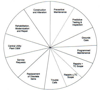 |
4.5.2. Figure 4-1 shows the specific elements making up a facilities maintenance AWP. Each element can be developed and considered as a separate entity. (In the figure, PM and PT&I are separated by a broken line because PT&I is considered a subset of PM. The same is true of repairs and TCs. Cumulatively, the elements define the total facilities maintenance program planned at a Center for a given year and the estimated cost in dollars and other resources (i.e., manpower, materials, and equipment). However, note that only routine maintenance and repairs are included as part of NRC's 2- to 4-percent of CRV recommended maintenance budget.
4.5.3. The AWP should include an estimate and allowance for reimbursable work. This is to ensure that reimbursable work will complement rather than compete with necessary maintenance work.
4.5.4. The dollar limits for a work package in each facilities maintenance work element are shown in Table 2-3. CoF projects, although not normally executed by the maintenance organization, are documented in the AWP to ensure coordination of construction and maintenance activities. Besides a listing of projects to be accomplished, the AWP should document any pertinent maintenance-related information that was identified during the design and development of the CoF projects.
Preparing an AWP requires specific information. The facilities and collateral equipment inventory, coupled with the RCM database, constitutes the basic information needed. Such an inventory database should be augmented by a variety of files and other key documents, including mission statements and objectives from the NASA and Center Strategic Plan and other policy documents, PM requirements, a continuous inspection program, historical funding data, Energy Efficiency and Water Conservation 5-year Plan (Appendix B, resource 7), and facilities history records. The CMMS is a valuable source of information on facility and equipment maintenance histories, criticality codes, priorities, performance metrics, TC histories and other unforeseen requirements on which to base a reasonable estimate of the required level of effort for each season of the year. See Appendix G for additional information on suggested information sources.
4.6.1. NASA Strategic Plan and Center Mission Statements. Pertinent excerpts from these documents set the stage for justifying to Congress and others why the funding is required and the ramifications to big-picture Government interests if the funding is not provided. From their guidance, the AWP should identify and illustrate why short- and long-termed facilities maintenance funding is absolutely crucial to ensuring facility availability for NASA's critical missions. The AWP builds upon the mission statements to provide guidance on setting priorities based on facilities and equipment criticality relative to mission, current condition, and long range plans that will affect real property assets and future maintenance requirements.
4.6.2. Center Master Plan and Other Planning Data. This planning documentation will identify not only future construction, acquisition and disposal plans for the Center that will ultimately impact on maintenance and resource requirements, but will also identify other short- and long-range planning information such as anticipated civil servant and contractor staffing requirements, opportunities for inter-service support agreements, and so forth. Information such as the expected staffing population is important to the AWP in that it is indicative of the level of work being performed at the Center at any time and can provide justification for adequate maintenance funding.
4.6.3. RCM (PM/PT&I) Database. This database, usually found in the CMMS, is required to develop PM and PT&I funding requirements for the next 5 years, including all labor, parts, materials and special tools. RCM may identify the most effective maintenance in terms of retaining the highest reliability at the lowest cost. It may even recommend that no maintenance action be taken on specific items, appearing contradictory to traditional maintenance philosophies. The RCM and PM/PT&I databases should provide the following:
a. Inventory of maintainable items.
b. Facility and equipment criticality and condition codes.
c. Specific inspections and maintenance tasks to be performed on each maintainable item of unattended, maintainable collateral equipment. These are periodic tasks to keep equipment items in good operating condition for improved reliability and to maximize their service lives.
d. The parameter (e.g., maximum allowable pressure drop, maximum allowable bearing temperature, recommended time interval between PM/PT&I service) defining when each PM/PT&I task should be performed.
e. The estimated resources required to perform each PM/PT&I task in terms of workhours (by craft), materials, tools, and equipment. The total of these estimated resource requirements becomes the basis for the PM/PT&I portion of the AWP, workforce staffing, and work scheduling. Also, these estimates can be used to balance the program.
f. Specific instructions for obtaining condition assessment information as part of each maintainable collateral equipment PM/PT&I. The information to be recorded includes the condition of the overall item of equipment and, in some cases, of a part or subsystem of the equipment item. Instructions should also define a procedure for describing and documenting the results of the condition assessment.
4.6.4. Facilities/Equipment History Database
4.6.4.1. Concurrent recording within the historical database of the condition of the items receiving PM/PT&I is one important product of the PM and PT&I programs. A continuous inspection program should be established to provide a basis for determining PGM and repair requirements for those items such as roofs, doors, walls, and windows that are not included in the PM or PT&I programs.
4.6.4.2. Once the facilities inventory is in place, it must be updated continuously to keep the inventory current and to maintain a detailed record of facilities condition. This is accomplished using the continuous inspection program. Historical files are a repository for all of the information on inventory items that is useful in preparing an AWP. These files must be structured carefully so that they include all necessary data, including the following:
a. Records of PM and PT&I work accomplished (i.e., identifying work completed, dates of performance, and costs in work hours and dollars).
b. Records of PGM and repair work accomplished (i.e., identifying PGM and repair work done, dates of work performance, and costs in work hours and dollars).
c. Condition assessment information developed during maintenance work.
d. Condition assessment information developed during the continuous inspection program.
e. Designation of candidate items for ROI.
f. Designation of candidate items for disposal or declaring excess.
4.7.1. Preventive Maintenance (PM). The PM requirements for maintainable collateral equipment items are defined using manufacturers' recommendations, R.S. Means Cost Data or similar guides, historical information, the technical expertise and experience of the maintenance staff, task and periodicity guidance from other Centers for like equipment, and other sources. After defining and summarizing the PM requirements relative to the work standards and identified tasks, their estimated costs in workhours and dollars for a fiscal year will be calculated. These totals define the level of effort (i.e., manpower and funds) required to accomplish the unconstrained PM program. Those figures would then be evaluated in terms of projected facilities maintenance funding and manpower levels and the estimated requirements for the other elements of the AWP. Such an evaluation is used to establish target resource allocations for the PM program on an annual basis during the 5-year planning period. See Table 2-3 for dollar limitations.
4.7.2. PT&I. PT&I involves gathering condition data on potential sources of failure. A PT&I program provides some of the condition data needed to carry on other elements (e.g., PGM or repair) of an AWP. Because it entails a dedicated effort drawing upon facilities resources, PT&I is an element of the AWP. PT&I can greatly impact an AWP because it extends the reach of the inspection program. For example, vibration analysis of a generator might be the basis for either accelerating or deferring a scheduled major overhaul, or infrared testing of a roof might indicate the need for small repairs now and avert a major CoF repair project in the future. See Table 2-3 for dollar limitations.
4.7.3. Grounds Care. Grounds care normally is accomplished with a relatively constant level of effort during the growing season. The level of effort can be predicted with a high degree of accuracy. See Table 2-3 for dollar limitations.
4.7.4. Programmed Maintenance (PGM)
4.7.4.1. PGM work refers to recurring work performed at longer than 1-year cycles and is best laid out in the 5-year Maintenance Plan. It involves predefined, specific work tasks. PGM work schedules often are determined on the basis of actual conditions, rather than by fixed intervals. Because of this reliance on condition data to schedule PGM tasks, a continuous inspection program that includes PT&I and user input is required. See Table 2-3 for dollar limitations.
4.7.4.2. Condition codes should be established and recorded in the RCM and facilities history database for each applicable inventory item maintenance function. They should be structured to trigger the identification of candidate PGM work when a certain condition level is recorded through the PT&I and continuous inspection programs.
4.7.4.3. Candidate PGM work can be costed and evaluated for programming in a particular annual program on the basis of projected funding levels. It is a case of analyzing all of the PGM requirements against other AWP requirements and allocating resources based on priorities. Work may be accomplished by civil service employees, incumbent support service contractors (if the work is determined to be within the scope of the contract), or by a separate, new contract.
4.7.5. Repair
4.7.5.1. Repair implies urgency because it involves fixing something broken or failing. It is work planned and executed as a single function; e.g., replacing a boiler or repairing leaking tanks. Non-CoF repair work must be within the Center Director's funding authority. See Table 2-3 for dollar limitations.
4.7.5.2. Repair requirements are identified from the RCM and continuous inspection programs, including input from users, occupants, and facility maintenance personnel. A clear distinction cannot always be made between PGM and repair. For example, pavement sealing and painting of entire structures are considered PGM, but repairing potholes and spot painting are considered repair. As a rule of thumb, repair usually involves fixing portions of an overall facility or system, whereas PGM involves some restoration of the entire system.
4.7.5.3. Local replacement criteria should be established. For example, barring extenuating circumstances, an item should be a candidate for replacement rather than repair if the repair cost exceeds 50-percent of the replacement cost.
4.7.6. Trouble Calls. TC's address items that break or are damaged unexpectedly. While a facilities maintenance manager uses the historical information in the CMMS to estimate in the AWP the expected level of TC effort, the manager should adjust the estimate upward to reflect inflation and physical plant additions and downward to reflect improvements in the maintenance program and decreases in the size of the physical plant. See Table 2-3 for dollar limitations.
4.7.7. Replacement of Obsolete Items (ROI). ROI requirements normally are identified through a variety of sources, particularly RCM analysis. For example, trends indicating that several same year, same model mechanical units used in a particular application are likely to fail in the near future may be indicative that the best course of action would be to replace all of them, regardless of past individual maintenance history; the breakdown of one of several same model pumps may lead to the discovery that parts are no longer available for that pump; PM inspection reports may identify equipment items failing to meet new electrical code requirements; or manufacturer's data for a newly purchased pump may indicate that similar onsite pumps are no longer parts-supportable. RCM database and equipment history files need to be structured and procedures established to recognize this type of information and to flag the associated equipment item as an ROI candidate. The facilities maintenance manager can then prioritize ROI candidates and evaluate them for replacement on the basis of safety and operational impact. See Table 2-3 for dollar limitations.
4.7.8. Service Requests. Small Service Requests are often performed by the same shop that performs TC work. While Service Requests are nonmaintenance work and do not fit within NRC's 2- to 4-percent of CRV suggested funding, small Service Requests are similar to small TC's in that they consist of minor facilities support work needed to maintain routine installation operations. An analysis of the TC's accomplished and the Service Request records identifies the relative levels of effort allocated to each of these similar elements of the AWP. Caution must be exercised to ensure that Service Request work does not take disproportionate precedence over important maintenance work. Normally, outside contractors perform work generated by large Service Requests. Service Request work includes facilities construction and additions costing less than the CoF $500,000 threshold. (Unless the CoF process as outlined in NPR 8820.2 is followed). See Table 2-3 for dollar limitations.
4.7.9. Central Utility Plant Operations and Maintenance. Central utility plant O&M normally requires a nearly constant level of effort (depending on the season), adjusted for inflation and the addition or deletion of facilities. See Table 2-3 for dollar limitations.
4.7.10. Rehabilitation, Modification, Repair, Construction, and Additions. Rehabilitation, modification, repair, construction, and additions are CoF categories described in NPD 8820.1, Design and Construction of Facilities, NPR 8820.2, Facility Project Implementation, NPD 7330.1, Approval Authorities for Facility Projects, and NASA FMM 9100, Financial Management Manual, Agencywide Coding Structure.
4.8.1. Facilities maintenance organizations in both the public and private sectors widely accept the concept of an AWP as an aid for both the budgetary and the work execution processes. The AWP can assist the facilities maintenance manager in establishing goals within projected resources and in planning to meet those goals. The AWP should evolve from a multiyear plan derived from a complete and continuously updated list of facilities requirements as shown in Figure 3-2. Such multiyear planning promotes achieving long-range goals and consistent direction in facilities maintenance management.
4.8.2. The 5-year Maintenance Plan is based on the total maintenance requirements, which in turn, are based on mission, criticalities, and established standards. This plan provides the necessary information for budget forecasting and initial planning and preparation of the AWP (see paragraph 4.3.1). This procedure ensures that the highest priority of maintenance work is scheduled and not lost in the budgeting process. The Plan should provide a balance of RCM to minimize the deferral of maintenance along with a realistic estimate of emergency and routine maintenance and repair. The plan should provide for the management of the BMAR such that the BMAR is controlled by a steady reduction of requirements or stabilized within the locally established guidelines of the Center.
4.8.3. Appendix G provides a template for producing 5-year and Annual Maintenance Plans. The 5-year Maintenance Plan is the result of a conscious evaluation of the NASA Strategic Plan, Center Master Plan, 5-year CoF Plan, and mission goals of the Center. A well-developed and up-to-date 5-year Maintenance Plan ensures that major maintenance repair or replacement is not wasted by the execution of a large CoF project or facility use change. Further, additional PM and PT&I funding can be programmed in advance to accommodate new growth and mission changes. This will ensure immediate and continued maintenance of new facilities as they come on line, thereby reducing future deterioration and premature failures.
4.9.1. Total Requirements
4.9.1.1. An elusive goal of facilities maintenance managers is to develop and maintain a system to define a complete, unconstrained list of all existing and predictable facilities maintenance work requirements. Such a list should include not only the BMAR, but also current and continuing requirements for PM, PT&I, Grounds Care, PGM, repair, TC's, ROI, and projections for new work to respond to evolving organizational and facilities maintenance requirements.
4.9.1.2. The total requirements should include estimates of unforeseen work that has a high degree of predictability (e.g., weather-related events such as thunderstorms and snowstorms). These requirements can easily add up and, unfortunately, are performed at the expense of routine maintenance, thereby increasing the BMAR. When this unforeseen work is quantified and programmed, it can be used to reduce BMAR during years when the unforeseen work is light.
4.9.1.3. The total maintenance requirements (shown in Figure 3-2), both identifiable and unforeseen can be compiled as a list or database to serve as the basis for defining the 5-year Facilities Maintenance Plan and the AWP. The database would then contain all potential facilities maintenance work. Thus, it should be the task of the facilities maintenance manager to use the database to construct the balanced AWP that most effectively responds to conflicting priorities within programmed resources.
4.9.2. Backlog of Maintenance and Repair (BMAR)
4.9.2.1. The BMAR, also known as "deferred maintenance," is the total of essential, but unfunded facilities maintenance work necessary to bring Centers to the required facilities maintenance standards. It is work that should be accomplished during the year but cannot be accomplished within available resources. It does not include new construction, additions, or modifications, but does include unfunded CoF repair projects.
4.9.2.2. BMAR is an excellent indicator of the condition of Center facilities and collateral equipment. It reflects the cumulative effects of underfunding facilities maintenance and repair. Review of BMAR trends and comparison of BMAR with the CRV and facilities maintenance funding provide indications of the adequacy of the resources devoted to facilities maintenance.
4.9.2.3. An annual reevaluation of the BMAR is necessary for the development of the AWP. This not only authenticates the work that continues to be deferred as BMAR, but it also identifies work items in the BMAR covering deficiencies that have progressed to the point where they need to be included in the AWP. See Chapter 9, Backlog of Maintenance and Repair, for a more detailed discussion on BMAR.
4.10.1. While most AWP preparation focuses on defining the requirements and matching those requirements to projected funding levels, the personnel resources required to execute an AWP are also a critical aspect of the planning process. The timely mobilization of personnel with the requisite skills is a complex task. Generally, three categories of personnel are available to execute the AWP: civil service personnel, support services contractors, and outside contractors.
4.10.2. As the 5-year Facilities Maintenance Plan evolves, the facilities maintenance manager should explore alternatives for matching projected work with personnel resources. The earlier the manager can define the work requirements, the more efficient mobilization of those resources can be. For example, if the 5-year Facilities Maintenance Plan indicates that electrical work will exceed current shop resources in three years, the manager can take steps early to adjust the support services contract or identify specific work to be performed by outside contractors.
4.10.3. The construction of new or altered facilities may also increase maintenance work requirements that should be planned for in advance. Otherwise, when the new or expanded facilities are accepted, there may be insufficient maintenance resources to accommodate them. This often leads to premature failures since no maintenance is provided for the new facilities, thereby increasing the life-cycle cost of facilities and equipment. Over time this can also result in additions to the BMAR.
This chapter describes the work functions required to execute a maintenance program. These functions begin with work generation and proceed through work reception and tracking, work order preparation, and work execution. The various steps required to perform these functions are described in this chapter. They are not meant to present an organizational structure but to include suggested functional work areas required to implement a maintenance program. Additionally, in this chapter, the term "shops" is used to refer to the facilities maintenance workforce, including both civil service employees and in most cases in NASA support services contract employees.
5.2.1. The AWP is the basis for a year's initial work planning (see Chapter 4, Annual Work Plan). This plan is augmented with customer requests, identification of new requirements, equipment breakdowns, and other emergent requirements. It is important to document the specific maintenance work items in the AWP and all requests for maintenance, repair, and service work. Work requested is received, processed, and if approved, converted into a work order as shown in Figure 5-1. Work disapproved for any number of reasons is returned to the customer with an explanation or request for clarification. Work that is valid but cannot be accomplished within the immediate resources is then deferred. If it is still valid at the end of the year and cannot be funded, it will be considered for inclusion in next year's AWP or the BMAR. All documents should be filed and retained in accordance with guidance provided in NPG 1441.1, Records Retention Schedules.
5.2.2. Centers should have work control systems that receive, classify, identify, estimate, approve, schedule, track, account for, analyze, and report all work throughout the facilities maintenance process, from inception to completion as shown in Figure 5-2. In NASA Centers the control system utilizes a Computerized Maintenance Management System (CMMS). It comprises the tools, techniques, checks, management controls, and documentation needed for effectively managing the workflow with an automated system (see Chapter 6, Facilities Maintenance Management Automation).
Work generation is the process of determining the maintenance workload in the facilities maintenance management system. A part of work generation is documenting the workload in the CMMS. Facilities maintenance work is comprised of recurring and nonrecurring maintenance work. Recurring work includes PM, PT&I, grounds care, central utility plant O&M, and the facilities condition assessment program. The recurring maintenance programs, customer needs, and facilities and equipment failures generate nonrecurring maintenance work in most cases.
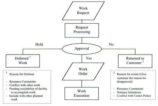 |
5.3.1. Facilities Maintenance Work. A significant portion of the facilities maintenance workload results from ownership and inventory. This is largely recurring/repetitive work that can be predicted based on knowledge of the maintainable facilities and collateral equipment and utilizing NASA's RCM program (see Chapter 7, Reliability Centered Maintenance). This work forms the basic elements of the AWP. Examples of this work include PM, PT&I, PGM, and recurring work such as grass cutting and relamping. The scope and extent of these kinds of work are typically defined when a facility is acquired (see Chapter 8, Reliability Centered Building and Equipment Acceptance).
5.3.2. Facilities Condition Assessment Program. In effective facilities maintenance programs, most of the facilities maintenance work other than PM and operator maintenance is generated from the facility condition assessment program and predictive testing conducted by or under the auspices of the facilities maintenance organization. Condition assessments are evaluations of Center facilities, including collateral equipment, utilizing continuous inspections, PT&I, and CMMS data. The inspections include those occurring during day-to-day maintenance operations; operator, user, and facility manager inspections; and separate supplemental inspections. The Center's CMMS TC and repair data is evaluated as a part of the condition assessment to determine trends that can be used in evaluating the condition of a facility and its maintenance program. The facility condition assessments are used to validate and update the Center's AWP, BMAR, ROI, and 5-year Plan. Chapter 10, Facilities Maintenance Standards and Actions, describes the condition assessment program and its inspections.
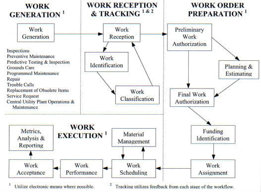 |
5.3.3. Trouble Calls
5.3.3.1. Normally, TC's are reported by telephone to the work reception desk. Operating the work reception desk is one of the functions performed by the work control center (see paragraph 5.4, Work Control Center). It is recognized that at some Centers the term "Trouble Call" means anything that is wrong and needs correcting. Therefore TC's coming to a work control center must be evaluated and coded (see paragraph 2.3.1, Facilities Maintenance Cost Account Codes). Only facilities maintenance and repair items should be included in the facilities program. Other items such as a coffee spill on a carpet, weeds that need to be removed, a floor needing to be cleaned, supplies needed in a restroom, ants or bugs in a desk needing pest control, must be assigned (coded) or passed along to the appropriate program. TC's must be properly coded to maintain records for facilities evaluations and budgets.
5.3.3.2. Although TC's can be placed by anyone, the recommended practice is to designate one individual in each major building or organization as the point of contact for placing TC's. This minimizes duplication of effort and simplifies work tracking. Emergency calls are accepted from anyone. In recognition of the limited scope of work covered by a TC, it is normally not estimated or scheduled, but it is tracked for execution. Appendix C, Figure C-1, is a sample format with data element definitions for a TC ticket that can be used to document and track TC's. This format should be automated to permit entering the request in the CMMS at a computer terminal and automatically issuing the work order to the shops. All documents and records should be filed and retained in accordance with guidance provided in NPG 1441.1, Records Retention Schedules.
5.3.4. Service Requests. A Service Request is new work requested by a customer. It may be either a small job that does not require planning and estimating or a large job that requires planning, estimating, and scheduling. The request may be submitted on a Request for Facilities Maintenance Services form as shown in Appendix C, Figure C-2 or another appropriate Center form. The form should be automated for submitting, recording, and processing the request. Normally, Service Requests are customer funded. All documents and records should be filed and retained in accordance with guidance provided in NPG 1441.1, Records Retention Schedules.
5.3.5. Other Requests. Other requests for facilities maintenance work include work not identified as part of the facilities maintenance inspection program. Examples are maintenance deficiencies found during a fire safety inspection or a request for repairs for a problem that has occurred since the last facilities maintenance inspection. These requests should be tracked separately to provide status and execution feedback to the customer and to monitor the effectiveness of the facilities maintenance inspection program.
5.4.1. The Work Control Center (WCC) is the nerve center for facilities maintenance management. It is the central location for managing the execution of facilities maintenance work. The following are WCC functions:
a. Receiving and logging work generated from all sources.
b. Assigning a unique identifier or designator to each work item.
c. Assigning initial classifications to the work.
d. Tracking the work as it progresses through the facilities maintenance system.
e. Maintaining records on requested work, inspections, jobs in progress, and completed work.
5.4.2. The work control function may be assigned to any organizational element in the facilities maintenance organization; however, it is suggested that it be assigned directly under the facilities maintenance manager, independent of the shops or planning and estimating functions. It may be staffed and operated by civil service or contract employees; however, if operated by a support services contractor, care must be taken to ensure that the contract specifies detailed performance requirements and that an effective quality assurance program is maintained. In addition, if the contractor is tasked with operating and maintaining the CMMS, the contract must provide for direct Government access to the CMMS facilities maintenance management database and report generators. This is required for purposes of queries on work status, analysis of work statistics, preparation of facilities maintenance reports, and facilities maintenance management surveillance. Providing CMMS terminals at designated Government offices will enable the Government to accomplish this.
The major work reception functions, in addition to ensuring that requested work is defined as clearly as circumstances permit, are as follows:
5.5.1. Work Reception. Work reception accepts and records work requirements resulting from the work generation process. Emergencies are evaluated when they are received in work control and the appropriate action is taken to assure the emergency situation is stabilized (see paragraph 5.7.2.5.a(4), Trouble Calls). Work reception initiates the administrative control of the work management data as the work progresses through the maintenance management system.
5.5.2. Work Identification. Each item of work is given a unique identifier or designator, much like a serial number. This identifier permits tracking the work item through its life-cycle of planning, approval as a work order, execution, and historical documentation. The identification scheme should meet the Center's needs. The use of automation simplifies the identification process. For example, CMMS-generated identifiers can be purely sequential numbers because the computer can track all of the attributes such as FMS codes, fiscal year, work classification, and fund source associated with each identification number. The work identifier should not be changed once it is assigned, even if the work is combined with another work item. The computer can provide the cross-reference to the combined identifier.
5.5.3. Work Classification
a. Work classification provides the ability to subject work to the proper levels of review and control and to perform management analyses of the workload. The suggested categories for work classification are discussed below. These categories extend beyond the minimum required for financial accounting and budgeting and provide additional detail for managing the facilities maintenance organization. They are important for managing the workload and understanding where resources are expended.
b. The use of automated systems permits ready accumulation and analysis of the data. Centers may wish to add additional classifications for local use. The following are some methods of classifying work:
(1) Funds type.
(2) Approval level.
(3) Work Elements.
(4) Special interest.
(5) Size.
(6) Method of accomplishment.
c. Each method is discussed below. Note that the work classification within any of these categories may be changed during the course of the work planning. Thus, the use of an unchanging, unique identification system such as described in paragraph 5.5.2, Work Identification, is particularly important.
5.5.3.1. Funds Type. Funds type describes whether the work is reimbursable or nonreimbursable. If the work is reimbursable, the fund citation normally identifies the customer; if nonreimbursable, the funds citation normally identifies the appropriation and project or program. Funds type is not the same as funds source because funds source does not identify the specific reimbursable customer, program, or project.
5.5.3.2. Approval Level. Approval level identifies who has the authority to approve the work. Specific approval levels are determined by Center policy and when documented, becomes a local "standard." Common practice is to delegate work approval authority to permit routine and recurring work approval at the lowest responsible level in the facilities maintenance organization. Some work such as TC's of an emergency or routine nature may be preapproved within specific guidelines. The designation of individuals authorized to approve work based on a hierarchy of cost, urgency, or other management considerations should be documented in the WCC.
5.5.3.3. Work Elements
a. Work element identifies which of the following standard work elements (see paragraph 1.5, Facilities Maintenance Definitions) applies:
(1) PM.
(2) PT&I.
(3) Grounds Care.
(4) PGM.
(5) Repair.
(6) TC.
(7) ROI.
(8) Service Request.
(9) Central Utility Plant O&M.
b. Work element categorization is useful in analyzing the relationships described in paragraph 3.11.1, Work Element Relationships.
5.5.3.4. Special Interest. This classification identifies and permits the accumulation of statistics on the work performed in support of specific or special-interest programs, initiatives, or work not otherwise accounted for by special funding programs. Examples include the following:
a. Energy Conservation.
b. Safety.
c. Environmental Compliance.
d. Handicapped Access.
e. Community Relations.
5.5.3.5. Size. Work size, grouped in dollar or level-of-effort ranges, indicates the amount of management effort required. This classification is useful in determining the type of funds used, the approval level, and the method of accomplishment.
5.5.3.6. Method of Accomplishment. The method of accomplishment identifies whether the work will be accomplished by civil service employees, by established support service contractors (if the work is determined to be within the contract scope), or under a separate, new contract.
5.5.4. Work Tracking System
5.5.4.1. A work tracking system enables work tracking from the time it enters the facilities maintenance system until it is either disapproved or completed. A Center's CMMS is the tool to be utilized for work tracking and status reporting.
5.5.4.2. Work status refers to the state of work progress in the facilities maintenance system as it proceeds from generation to completion. It includes the identification of actions completed, actions pending, responsible parties, and milestone dates. Work status is a key element in maintaining good customer relations by making it possible to provide responsive feedback to the customer. The CMMS should provide the means for documenting and reviewing work status. A suggested way of accomplishing this is assigning status codes or milestone data to each item of work. Personnel with CMMS access can then examine the status information and use it when preparing reports.
5.5.4.3. As a minimum, the CMMS should contain the estimated or actual start and completion dates and identify the responsible party for each of the following milestones in the facilities maintenance process:
a. Work Reception (including classification and identification phases).
b. Planning and Estimating.
c. Final Authorization.
d. Scheduling.
e. Material Management.
f. Work Performance.
g. Final Inspection.
5.5.4.4. Not all milestones are applicable to all work. For example, for TC's only status information related to work reception and work performance would be tracked. Data for final authorization, scheduling, material, work performance, and final inspection would not be recorded for requests for cost estimates only. The shop load plan and master schedule typically contain material and work performance status information for scheduled work.
a. The work order (Appendix C, Figure C-3) is the document directing facilities maintenance work execution once the requested work has been approved. Normally, Planners and Estimators (P&E) prepare work orders. An exception is the TC ticket discussed in paragraph 5.6.b. below. The work order includes an estimate of the resources required to perform the job (workhours by craft, materials, equipment, tools, and specialized support); the steps or tasks required performing the job, and documentation of coordination and outages required. It should also include safety requirements, job priority, job accounting information, and any other information required by management and the shops to schedule, perform, and evaluate the work. Safety requirements should include, but not be limited to, appropriate safety items such as confined space entry, lockout/tag out, oxygen depletion, chemical or explosive handling, fall protection, safety training and certification requirements, and any other specific safety requirements associated with the task to be accomplished under the work order. The work order form should be automated (included in the CMMS).
b. For small jobs, typically less than 20 workhours, the cost of detailed planning and estimating and scheduling may exceed the benefit; however, the craft supervisor responsible for the TC must review the TC task and specify safety requirements such as those in paragraph 5.6.a above. In these cases, use of a TC ticket format (Appendix C, Figure C-1) is suggested. This ticket should be automated (included in the CMMS).
5.6.1. Review, Screening, and Authorization. Work review, screening, and authorization is typically a two-step process. Requests for work receive an initial screening prior to job planning and estimating. The second step provides final approval and release of the planned and estimated work order for scheduling. In the case of TC's and work on small jobs, this may be accomplished in one step, within the decision authority of the work reception desk, bypassing planning and estimating. The dotted arrow connecting the preliminary and final work authorization blocks in Figure 5-2 symbolizes this.
5.6.1.1. Preliminary Work Authorization. Authorization is the process by which facilities maintenance work is approved for performance. This may be a phased process in which preliminary approval is obtained prior to detailed planning and estimating as shown in Figure 5-2. The preliminary screening determines if requested work should be accepted for continued processing, rejected, returned to the customer for additional information, or given preliminary approval for detailed planning and estimating. For work of limited scope, it may also serve as the final authorization if funds are available.
5.6.1.2. Final Authorization
a. Once the work order is planned and estimated, it is forwarded for final authorization. The review process checks the work order to ensure that it is responsive; complies with applicable safety, health, environmental, and security standards; is within the scope of the AWP; and is within funding and approval levels. This review normally takes place in the facilities maintenance organization; however, on complex or critical jobs, the customer should review the work order to check its technical adequacy.
b. When reviews are completed and funds are available, the work order is authorized for execution by the appropriate approving official (see paragraph 5.5.3.2, Approval Level).
5.6.2. Planning and Estimating. Center work control systems should contain a planning and estimating function. This function provides the detailed definition of maintenance tasks or steps to be taken, the resources required (material, equipment, tools, and labor), and special considerations such as safety outages and coordination. It supports budgeting, resource allocation, and work performance decision processes and provides a benchmark for work performance evaluation. A part of the planning and estimating function is the process of developing the work order documenting the detailed work tasks and preparing an estimate of the resources required. The work order includes statements of the job steps or phases for each craft, a list of the required materials, and the identification of special tools or equipment needed. It includes an estimate of the time required for each phase, copies of sketches or drawings, the identification of safety requirements and required outages, and allowances for staging, travel, site cleanup, and other job-related actions. For contracted work, the work order is replaced by the Statement of Work (SOW) that includes sketches, a job specification or performance work statement, and a cost estimate appropriate to the contract form used. Planning and estimating provide the basis for the following:
a. Deciding to approve, disapprove, or defer work.
b. Developing costs and budget estimates.
c. Determining the method of accomplishment.
d. Preparing the shop load plan, the master schedule, and the shop schedule.
e. Evaluating shop or contractor performance and efficiency.
f. Establishing contract costs.
5.6.2.1. Facilities Maintenance Standards. Facilities maintenance standards are discussed in Chapter 10, Facilities Maintenance Standards and Actions. They establish the level and condition to which facilities and equipment are maintained. Standards serve as guides in determining the facilities maintenance work. P&E's determine the job tasks by comparing existing conditions with the prescribed maintenance standards and then selecting job tasks (maintenance actions) that bring the facility up to those standards./p>
5.6.2.2. Performance Standards. Planning and estimating is a skill requiring substantial knowledge of the crafts and methods involved; however, it is unlikely that one person is expert in all aspects of a craft. There are a number of estimating guides and standards available to assist P&E's in preparing work orders and estimates (see list in Appendix B). Equipment manufacturers also produce standards. All standards must be applied with care, taking into consideration local conditions, area cost factors, and experience. However, use of cost estimating guides and standards is encouraged as a means of improving the quality, reliability, and consistency of estimates.
5.6.2.3. Work Planning. Work planning consists of identifying specific tasks to be performed, phasing those tasks, identifying the skills and crafts required for the tasks, and specifying the material and equipment for the tasks. It includes identifying specific health and safety requirements, coordination, outages, equipment availability, and other constraining parameters. As with the other P&E functions, established standards also can provide assistance in work planning. Table 5-1 provides examples of selected facilities maintenance tasks, with the cycle or interval between performances of the task suggested for use by NASA Centers. The intervals listed assume average conditions. Centers may adjust these to suit local use and environmental conditions.
5.6.2.4. Cost Estimating. Cost estimates are developed by multiplying unit labor, equipment, and material costs by job task quantities and adding the appropriate burden rates for overhead and indirect costs. The exact form of the cost estimate depends on its intended use. For example, overhead costs, profit, bond expense, and taxes required for contract work are omitted for in-house work. Cost estimates can be classified based on the amount of detail considered in their preparation as Scoping estimates or final estimates. Cost estimates normally are prepared using industry-accepted standards (see
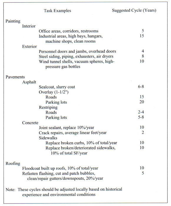 |
Appendix B, resources 41 through 50) or historical data. These factors are discussed in the following paragraphs:
a. Scoping Estimate. This estimate is based on broad, unit cost guidelines; it does not involve a detailed job plan or design. It is not appropriate as the basis for job performance evaluation or contract negotiations. The scoping estimate is used in situations that do not call for details and high accuracy. Examples include estimates for developing budgets, estimates to aid in screening work packages to be included in the BMAR, or preliminary estimates for initial decision making on a request for work.
b. Final Estimate. This estimate is based on detailed job plans (as found in a facilities maintenance work order) or final contract plans and specifications. It is more reliable than a Scoping estimate. Job performance evaluations, contract negotiations, or other exacting uses should be based on a final estimate because it reflects a detailed knowledge of the individual facilities maintenance actions and the resources required. A final estimate can substitute for a scoping estimate, but it is more costly to produce.
c. Historical Estimate. The historical estimate uses prior performance of the maintenance tasks involved as its basis. It can have excellent validity, provided the new job tasks and methods are comparable to the historical database used in preparing the estimate. There is minimal cost in developing an historical estimate. However, care must be taken to ensure that the historical data applies to the current job scope. Periodic validation of historical-based estimates against estimating standards is necessary to ensure that they are in line with accepted standards. This type estimate is especially valuable for repetitive or recurring tasks such as PM.
5.6.3. Funding Identification. Funding identification covers the identification, allocation, and authorization of the proper funds. It includes Center operating funds, customer reimbursable funds, and special funds.
5.6.3.1. Each work order includes a funding citation and accounting data identifying which funds to charge for the work. In some cases, funds are customer furnished (reimbursable). In others, funds are specifically budgeted by the Center for facilities maintenance. When work is customer funded, appropriate funding documents should be furnished in a timely manner to ensure that work is not delayed unnecessarily. A correct funding citation ensures that the proper account is charged and provides valid accounting data for management reporting.
5.6.3.2. Customer-funded work could be time sensitive to support a given mission. As a result, a suspense system should be in place to track work requests waiting for funding to preclude unnecessary administrative delays and customer dissatisfaction.
5.6.4. Priority Systems
5.6.4.1. The work order system must make provision for differing work priorities. This allows high-priority work to be done first while managing all work to ensure its accomplishment in accordance with Center needs. Figure 5-3 is a sample priority system. The priority is normally determined as part of the work review process. It guides material procurement, scheduling, and work execution.
5.6.4.2. Priorities require periodic review to ensure that they conform to organization and mission needs. When using a CMMS, a special designator can be added to the database to help track high-visibility projects. An example would be safety items from an inspection. While these items could fall in several of the priorities shown in Figure 5-3, they may need to be tracked as a group for accomplishment. A special local code designation will ensure that they can be readily highlighted for management purposes.
GENERAL MAINTENANCE WORK PRIORITY SYSTEM |
Priority/Description |
Narrative |
| 1. Emergency | Safety of life or property threatened; immediate mission impact; loss of utilities. Begin immediately; divert resources as necessary; overtime may be authorized. |
| 2. Urgent | Maintenance or repair work required for continued facility operation; should be completed to ensure continuous operation of the facility and to restore healthful environment. Not a life-threatening emergency. Respond upon completion of current work but within a specified period of time (specified by local Center, such as same day or within 4 hours). |
| 3. Priority | Work that is to support the mission on a priority basis or to meet project deadlines. Complete in order of receipt with mission work taking priority. |
| 4. Routine | The facilities maintenance work can be scheduled routinely within the capability of the facilities maintenance organization. Facilities work is subject to availability of resources, and may be consolidated by facility or zone or as directed to obtain efficiency of operation. |
| 5. Discretionary | Work that is desired but not essential to protect, preserve, or restore facilities and equipment; typically, new work that is not tied to a specific mission milestone. |
| 6. Deferred | Work that may be safely, operationally, and economically postponed. The work should be done, but cannot be scheduled because of higher priority work, funds shortage, work site access, or conditions outside the control of the maintenance organization. The work may be reclassified if conditions permit or included in the BMAR. |
After planning and approval comes work execution which includes the following:
a. Obtaining material, tools, and equipment.
b. Scheduling the work.
c. Performing the work.
d. Monitoring work accomplishment.
e. Final Inspection.
f. Reporting work completion.
5.7.1. Material Management
5.7.1.1. Material management includes ordering, stocking, storing, staging, issuing, and receiving material for use on work orders. Material management may be performed by an element of the facilities maintenance organization, a central supply department not a part of the facilities maintenance organization, or a combination of these. (Tool management may be assigned to the same organization that has the material management responsibility.) Working from material requirements lists prepared by P&E's as part of the work order, the material manager is responsible for obtaining the material and advising the work schedulers when the material is available for job accomplishment. In the case of PM, other recurring and standing work, and TC's, material managers should have available or provide ready access to frequently used parts and supplies. This material may be preexpended shelf stock, or it may be available from vendors by use of a Government credit card or from vendors who are accessible under quick procurement instruments such as blanket purchase agreements.
5.7.1.2. The range and depth of material stocked should be based on historical demand, standby items (spares for critical systems), and projected requirements for future work. Inventory high and low limits should be established based on use rates, economic reorder quantities, and delivery times to minimize investment in inventory. Where advantageous, alternate material management strategies can be used such as "just-in-time" parts delivery. The benefits available are the reduction in inventory costs associated with storage, management, pilferage, and cannibalization. Many automated maintenance management systems include support for computerized material management functions. Bar coding is used extensively in material management to speed data entry and reduce data entry errors.
5.7.2. Scheduling. Scheduling work orders is necessary to ensure a balanced flow of work to the shops in accordance with priorities, external factors (such as weather), and operational considerations. It facilitates optimum use of resources and provides information to optimize the distribution of shop staffing by craft. The AWP identifies resource levels for each facilities maintenance program work element. It also identifies major work items to a fiscal year. However, most facilities maintenance work orders, including Service Requests, will not have individual visibility in the AWP. They are included as part of a level-of-effort resource allocation for the fiscal year. Within the fiscal year, work scheduling may be done at three levels: the shop load plan, the master schedule, and the shop schedule. The relationship of these plans is depicted in Figure 5-4.
5.7.2.1. Shop Load Plan
a. The shop load plan is usually maintained by the organizational element responsible for the work control function. It schedules work to the shops on a periodic basis, typically quarterly, and looks several quarters into the future. This plan reflects the backlog of estimated work as defined in the AWP for the current and following year. Work may be added or shifted among the schedule periods as new work is identified or work priorities change, although the plan for the next schedule period should be fairly stable. A Center may find it convenient to divide the next quarter's shop load plan into a short-term (30-day) plan and a mid-term (following 60 days) plan for closer scheduling.
b. The shop load plan considers available production resources (i.e., workhours by craft, tools and special equipment, and contract limitations), availability of items to be maintained such as times for shutdowns, and external factors such as weather. It considers work already scheduled or in progress; allowances for recurring work such as PM, PT&I, and TC's; and long-lead-time material requirements. With these factors in mind, the planner loads work orders into each quarter to balance the workload for each maintenance resource and to ensure optimum employment of that resource within the work order priority system.
c. The shop load plan also facilitates analyzing the workforce composition compared to the workload. It identifies personnel or skill shortages or excesses and gives facilities maintenance managers time to respond. Close coordination with the master schedule regarding the status of work in progress is required. Appendix C, Figure C-6, contains a sample shop load plan.
5.7.2.2. Master Schedule. The master schedule is maintained in the shop organization, usually under the direction of the senior shop supervisor. Within the scheduling framework of the shop load plan, it is the week-by-week shop schedule, identifying jobs to individual shops. It covers a shorter time period than the shop load plan, typically 6 to 12 weeks. Work orders are initially placed in the master schedule and noted as awaiting material. When material is available and the job is ready to start, it is firmly scheduled. Close coordination with the shop load plan and shop schedules is required. The master schedule changes as priorities are adjusted, new work is identified, and material status changes. The shop load plan can be used as a model for the master schedule. Appendix C, Figure C-7, contains a sample master schedule.
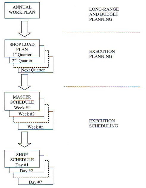 |
5.7.2.3. Shop Schedule. Within the framework of the master schedule, the shop schedule is used to schedule the day-by-day work orders and craft personnel within a shop. It is maintained by the shop supervisor and used to assign work and track progress. The shop schedule can be patterned after the master schedule. Appendix D, Figure D-8, includes a sample shop schedule.
5.7.2.4. Schedule Automation. The shop load plan, master schedule, and shop schedule are all based on the same database, differing slightly in the information displayed and the period covered. It is possible to maintain a single scheduling system on a networked CMMS working from a shared database, provided the CMMS has the necessary scheduling features. This gives the added advantage of automatically coordinating the schedules and changes at all levels of management. Some CMMS's may have an integrated scheduling module (See Appendix D, paragraph 8, Work Management, for a sample work scheduling module) that provides functional equivalents to the shop load plan, the master schedule, and the shop schedules that can be used to prepare detailed project schedules for the more complex work projects.
5.7.2.5. Scheduling Considerations
a. The following factors should be considered in scheduling work performance:
(1) Preventive Maintenance. PM (including PT&I) provides the baseline workload for the facilities maintenance shops. An effective PM program minimizes the need for TC's and repair. Efficiencies can be obtained by using employees dedicated to PM work because they become familiar with the equipment. PM work orders should be scheduled and grouped by facility or geographical area to minimize travel.
(2) One-time Work Orders. Work orders for one-time jobs require the greatest scheduling coordination and management effort. This is due to the unique requirements of each job.
(3) Repetitive Work Orders. These are similar to PM jobs in that they are a predictable level of effort and frequently are a continuing or repeating work requirement such as Grounds Care, street sweeping, relamping, and Central Utility Plant Operations Maintenance. Like PM, they are scheduled as part of the baseline shop workload.
(4) Trouble Calls. TC's of an emergency nature are assigned to the shop most qualified to address the problem and take precedence over any other work, including work in progress. This TC work proceeds until the situation is corrected or stabilized. The final correction of a problem, such as a water main break, may require subsequent issue of a repair work order. Most Routine TC's can be accomplished by the work center assigned to perform small jobs, as discussed in paragraph 3.4.7, Work Grouping. Equipping key facilities maintenance workers with radios, cell phones or pagers can enhance their response and productivity.
(5) Small Jobs. Small jobs, typically those requiring less than 20 workhours and issued on TC tickets, are normally worked on a first-come, first-served basis, subject to the availability of material. Because they can represent a fairly constant level of effort and normally involve routine methods and materials, it is common practice to have a shop dedicated to this size work.
b. When a TC shop is used, it should be able to complete about 90-percent of TC's and small work orders; the remaining 10-percent are used as fill-in work for other shops. This shop should be sized to be able to complete urgent (nonemergency) work within the day and nonemergency routine work within 5 to 10 workdays of receipt, subject to material availability. The size and type of TC Shop depends on local conditions and historical data such as volume, nature of work, geographic proximity, and availability of transportation and materials. In the interest of efficiency and minimizing travel time, small jobs may be grouped by building or geographic area. The use of dedicated, radio-equipped vehicles stocked with preexpended, commonly used facilities maintenance material and proper tools will improve productivity.
5.7.3. Work Performance. When all material is available and coordination and scheduling are completed, the work order is executed. Work proceeds to completion in accordance with the approved work order. However, the shops should be free to communicate with the P&E's to resolve questions about the work. If field conditions differ substantially from the work order, or the effort and material required differ substantially from the work order estimate, the supervisor should check with the P&E for an amendment or clarification and review the priority and schedule to ensure that completion dates will not be missed. The threshold for a work order amendment is based on Center management needs; however, a 20-percent or greater increase from the estimate is suggested as a deviation requiring a work order amendment.
5.7.3.1. Quality Control. This function is a responsibility of the organization executing the work. Shop supervisors usually have the primary responsibility for work quality control based on policies and procedures of the organization responsible for the work.
5.7.3.2. Quality Assurance (QA). Regardless of who performs work it should be subject to inspections for quality and compliance with work requirements. See paragraph 3.4.10, Quality Assurance, and Chapter 12, Contract Support, for details on quality assurance programs.
5.7.4. Work Acceptance
5.7.4.1. Final Inspection. Final inspections are performed as appropriate depending on the nature and size of the completed work. If the work to be inspected is for a customer, the customer should participate in the final inspection in order to accept the work. If customer expectation goes beyond the work order scope, the job should be referred promptly to the facilities maintenance manager for resolution.
5.7.4.2. Defective Work. Defective or rejected work occurs for a number of reasons, including poor workmanship, an incorrectly scoped and prepared work order, defective material, or poorly defined customer requirements. When defective work is discovered, it should be corrected to satisfy the operational needs and to meet safety requirements. Correction of safety related deficiencies should be accomplished immediately.
5.7.4.3. Rework Causes and Correction
a. A decision to rework a job should be based on cost-benefit considerations, including Center operational commitments, cost to rework the job, expected added benefit as a result of rework, and availability of resources. Separate work orders should be established to accumulate rework data. Other factors, which would require rework, are jobs that do not meet safety regulations and/or other mandatory laws. The evaluation process should address causes of defective work and methods of reducing rework. Remedial actions may include revising internal procedures such as quality control procedures, providing additional employee training and skill development, changing material specifications, adding early material acceptance inspections, revising facilities maintenance standards and requirements, and increasing customer involvement with work order preparation and approval. Each Center should have a policy for handling rework. In cases where rework of contract efforts is being considered, the cognizant procurement office must be consulted.
b. In general, the customer should not have to bear the cost of facilities maintenance rework resulting from errors by another party, and the Government should not have to bear the cost of rework that results from a contractor's error or negligence. Inspection clauses must be included in contracts to require the contractor to perform rework at the contractors own expense, to reimburse the Government for rework performed by the Government, or to reduce contractor payments for rework not performed. The amount of rework should be considered as an evaluation factor when determining contract award fees.
5.7.4.4. Completion Reporting. When the work has been completed and accepted a completion report is submitted. This reporting involves recording in the CMMS the work completion and the resources used, and closing the work order. Care must be exercised to identify and record all of the work accomplished, particularly when the initial request is sketchy or incomplete. The labor and material used are recorded for record and accounting purposes. The results are recorded in the facility or equipment history files, and evaluation action is initiated. The information reported should include unanticipated conditions encountered, a concise description of the work accomplished, and additional material used but not listed in the work order. Work order forms (including TC tickets) should include space for the technician to enter completion data. Shop supervisors should review the completion data. All documents and records should be filed and retained in accordance with guidance provided in NPG 1441.1, Records Retention Schedules.
5.7.5. Management Information (Metrics, Analysis, and Reporting). The loop on the maintenance management system is closed by evaluating completed work to compare actual work performance with estimates, for quality assurance (whether performed in-house or by contract) and to ensure conformance with work order instructions, standards, customer satisfaction, and accuracy of completed work for costing and reporting purposes. It appraises the performance of each element of the facilities maintenance management system and initiates corrective action when needed. Thus, evaluation provides for the continuous improvement of workflow through the organization and the CMMS.
5.7.5.1. Determining Information Requirements. Reports, charts, and other displays that do not directly contribute to facilities maintenance management, other Center, or NASA Headquarters needs are a waste of scarce resources. Therefore, information should be collected, processed, or documented to support a clear need. A summary of recommended facilities maintenance indicators and reports is given in paragraph 5.7.5.3, Analysis, Reports, and Records. Centers should specify the information to be displayed and distributed in their reports. Data that is not required to support management functions should not be collected or maintained. Over time, much data loses its value to the manager. For example, a summary of last year's TC's by month and by trade would be more useful to the manager at this point than a voluminous record of all the actual calls. Managers must develop archiving plans to reduce the volume of outdated data in the active database while retaining those elements of the data that are useful for trending and analysis. The archived data also must be maintained for possible future use in providing historical data for performance-based contracts.
5.7.5.2. Covered Functions. As discussed in Chapter 6, Facilities Maintenance Management Automation, the Center's CMMS includes day-to-day work records and historical data. This electronic data and information from other electronic systems that may or may not interface with the CMMS can be used to cover the full range of facilities maintenance functions.
5.7.5.3. Analysis, Reports, and Records
a. One major function of a CMMS is to provide maintenance data for automated analysis and reports to support management needs. The analysis should examine both status and trends. Graphical presentation of numerical data and trends will aid managers in understanding the implications of the data. The following discussion of several types of analyses and reports may be important to a facilities maintenance manager.
b. Information provided in the reports is available for analysis with metrics, as discussed in paragraph 3.11, Management Indicators, and Appendix F. This analysis is a portion of the facilities maintenance program shown in Figure 3-2.
c. The following descriptions are intentionally unstructured. Managers should select and tailor them to fit local data and needs.
(1) Status Reports. The following reports would provide a "snapshot" of where one is at a given point in time:
(i) Inventory. This report could include displays of facilities and maintainable collateral equipment inventory statistics, use, user, age profiles, and similar data. Significant portions of this information can be used in space management and planning.
(ii) Status of Funds. This type report would provide up-to-date status of funds by source, including amounts authorized, reserved, and obligated. It also includes a comparison of planned to actual expenditure rates.
(iii) Status of Work. This report, which should be obtained from CMMS data, could provide the status of all work submitted to the facilities maintenance organization. It would show a short title for the work, work generation date, who or which organizational element has action, and an estimated completion date where possible. Variations of this report could include arranging the information by customer, work classification, status (grouping work items with similar status into one report), or facility. It could take the form of a history of selected work items showing their progress through the facilities maintenance system.
(iv) Status of Major Projects. This report would include major undertakings such as Construction of Facilities (CoF) projects, major facilities maintenance projects, and projects of special Center interest. The reports should reflect cost estimates, project milestones, and progress against those milestones.
(v) AWP Execution Status. The CMMS should provide a display of annual resource requirements and the status for the major line items within each element that makes up the AWP. This includes PM, PT&I, Grounds Care, PGM, repair, TC, ROI, Service Requests, Central Utilities Plant Operations & Maintenance, CoF, and related factors. It also should display current budget estimates for out-years and the BMAR.
(vi) Status of BMAR. This report should give the facilities maintenance manager an update on the amount of BMAR by facility and facility classification (Mission Direct support, Mission Support, and Center Support) and total for the Center. It is also desirable to know the amount of BMAR by type of work such as roofs, Heating, Ventilating, and Air Conditioning (HVAC) systems, structures, roads, and similar systems. This will facilitate long-range programming in the 5-year Maintenance Plan and provide information for the NASA Headquarters Metrics (see paragraph 3.11.6.2, NASA Headquarters Metrics).
(vii) Contracts. This report could include the status of contracts, contract execution, pending and executed modifications, and delivery orders. This should cover support service, one-time facilities maintenance, and CoF contracts.
(viii) Materials. This report could include the status of materials inventory, orders, and jobs awaiting material.
(2) Work Performance Reports
(i) Work Input. Reports on work input include statistics on work generation and the characteristics of that work. They may include information on Service Requests (arranged and tabulated by date of request, customer, special interest area, facility number, and craft) and work orders generated by the inspection program (PM inspections, PT&I, continuous inspections, operator inspections, and specialized inspections), PM program, PGM program, repair program, and TC's.
(ii) Work Execution. Reports on work execution include information on shop schedules, planned work, job status, estimated versus actual job performance, delayed or late jobs, and related performance indicators. They also include progress on the PM, PGM, PT&I, and condition assessment programs.
(iii) Utilities. This report would contain information on production, consumption, costs, conservation measures and targets, and related factors such as weather profiles.
(iv) Other Reports. This category is a catchall for those reports not directly tied to facilities maintenance but closely related or supporting facilities maintenance efforts. Examples include personnel status, correspondence tickler and tracking, and automation system statistics.
6.1.1. A requirement exists for facilities maintenance managers throughout NASA to use modern maintenance systems and methods to control their work activities, account for resources they are provided and to monitor and report work execution through the full use of various industry standard metrics and other management indicators. Because of the scope, complexity, and high value of the NASA Center facility inventories, all NASA Centers and most Component Activities use CMMS.
6.1.2. The past decades have seen the application of computer technology to facilities maintenance management expand as systems became more powerful, less costly, and easier to use. NASA Centers have acquired and implemented various CMMS's for use in managing their facilities maintenance program. In many cases, the CMMS shares information interactively with other systems and provides for direct system access by end users.
6.1.3. The Center maintenance data entered in a CMMS is Government property and, as such, must be available for Government use and retention for historical purposes, regardless of who, Government or contractor, is responsible for populating and maintaining the database. Where a contractor operates the CMMS it must be made clear in the contractor's contract that the CMMS maintenance data is Government property and must be turned over to the Government at the end of the contract.
Chapter 3, Facilities Maintenance Management, discusses the functions, processes, management concepts, and system of controls recommended for facilities maintenance. Centers should evaluate their maintenance management data requirements and establish their electronic data needs prior to investigating and acquiring a new CMMS or modifying an existing CMMS. Centers should acquire only what is required to accomplish the maintenance organization goals. Of course, once a CMMS is acquired, resources must be dedicated to initially populate the systems (modules) and to continually keep them up to date. The data once entered must be utilized for day-to-day operations and management of the Centers maintenance program to be cost effective. Periodic review of the CMMS data should be made to keep the system abreast of current requirements, deleting unnecessary data entries and adding new ones as required.
Facilities maintenance management automation brings the benefits of automation to facilities maintenance functions and processes. Chapter 3, Facilities Maintenance Management, not only discusses functions recommended for facilities maintenance but also identifies closely related supporting functions and processes. The CMMS should directly support or interface with existing related automated systems such as financial accounting (Asset Management System (AMS) module of the Integrated Financial Management Program (IFMP)), RCM databases and personnel administration systems.
The Center's CMMS must support the major functions discussed in the following paragraphs as they apply to facilities maintenance. Information entered in the functional areas of the CMMS is critical for the day-to-day maintenance operations, management of the Center's maintenance program, for providing data to support the budget process, and for providing historical information critical for use in performance-based contracting. In all of the functional areas, items entered should contain FMS codes and key management information such as criticality codes, condition codes, and downtime associated with an item. Descriptive nomenclature of items must be standardized to permit for the sorting of data. If data is available in separate databases, Centers must provide a link between those and the CMMS in order to collect total maintenance costs, including material and subcontract costs. See Appendix D for typical monitor screen CMMS images used for various functions.
6.4.1. Manage Facilities and Equipment. This function contains the facilities maintenance processes and procedures to be utilized in managing the facilities maintenance workload. In addition to the automation of the administrative processing associated with maintenance management, the major advantage of having a CMMS is the capability to process a large amount of data in order to identify trends that would not be readily apparent by reviewing individual work orders. This processing provides the data needed for benchmarking and for preparing facility condition assessments. A major effort of the CMMS is tying together the various RCM activities. This function also includes facilities planning and processes normally associated with CoF funding and must support those portions of CoF work that are a logical outgrowth of the facilities maintenance effort such as repair, modification, or rehabilitation. The following paragraphs highlight files/modules which are a part of most CMMS's and that are used in managing maintenance programs.
6.4.1.1. Facility/Equipment Inventory. These data files/modules contain a detailed inventory of all facilities and maintainable collateral equipment subject to the facilities maintenance management system (and could include other information if needed for planning, space management, or accounting purposes). For facilities, they include information such as identifier, size, cost, date acquired, category codes, uses, location, users, material condition codes, and other similar information. For equipment, they include nomenclature, manufacturer, part number, cost, serial number, date acquired, size, location, identifiers to major system or use, warranty, specific facilities maintenance requirements, life expectancy, and similar information. Current and reliable data will enhance analysis and budget preparation and may be needed in developing customer charges under NASA's Full Cost Accounting System. Tables 3-2 and 3-3 list representative data elements.
6.4.1.2. Work Input, Control and Scheduling. This data file/module contains information on work requested by customers, work generated internally, and work status as it proceeds from requirement identification to work completion or request disapproval. It includes information on customer, cost estimate, funding, scheduling for execution, and execution status for each work order. This data provides the ability to track facilities projects, requests for facilities maintenance, TC's, and Service Requests. The CMMS may include the capability to receive work requests electronically and accomplish the approval process electronically. Centers should establish a website on the local internet to provide customers with a link to work status reports and any other appropriate maintenance information. A selective combination of electronic and voice interface with customers would probably provide the best support. Appendix C provides sample forms for use in facilities maintenance, including several in CMMS database formats.
6.4.1.3. Reliability Centered Maintenance. This data file/module contains information on facilities and equipment criticality codes, maintenance requirements and schedules. It contains data for equipment and facilities maintenance actions required, predictive testing test points, diagnostic aids, references to or excerpts from maintenance manuals and equipment drawings, schedules, frequency, materials, safety requirements, and related procedures. Linked with the inventory, the combined data files can be used to create PT&I schedules, PM schedules, and work orders or PM task descriptions for use by technicians and mechanics. Criticality codes will be recorded, but updated on an iterative basis as missions and environments change. The CMMS should include the ability to analyze PT&I results, process parameters (including normal baseline temperature, pressure, and flow readings), diagnose the possible causes of abnormal readings, project trends in test results, and schedule facilities maintenance actions or further inspection based on the trends. PT&I Finds and their corrective work should be identified in the CMMS to ensure that priority work is highlighted and tracked. Information and data in the PT&I database should be made available to maintenance engineers, managers and craftspersons through the CMMS. This will ensure that pertinent information needed for maintenance and failure analysis is readily available.
6.4.1.4. Correlation of Maintenance Data. Much benefit can be realized by correlation of various metrics, trends, and data from the PM, PT&I, and other databases. An important function of a CMMS is to automate that correlation as new input is made, with limits that alarm for followup action.
6.4.1.5. Continuous Inspection. This data file/module contains information for the continuous inspection program. (see paragraph 10.5, Continuous Inspection.) It should include facilities maintenance standards, facility condition inspection schedules, and inspection and test procedures. Linked with the inventory, it can be used to create the inspection orders and work sheets used by inspectors. The results of inspections from PT&I's, PM's, operators, Facility Managers, facility users, and Facility Condition Inspections should be entered in the CMMS's history files for use in the FCA.
6.4.1.6. Facility/Equipment History. These data files/module contain summaries of the maintenance histories of the facilities and collateral equipment. They contain summaries of PM, PGM, repairs, TC, rehabilitation, modifications, additions, construction, and other work affecting the configuration or condition of the items. They include completed and canceled work orders. These files also include the current material condition assessment of each item, derived from the continuous inspection program, for use in developing the FCA and the BMAR. By using the CMMS to tie the FCA to the continuous inspection program and specifically to the PT&I database, condition assessments will be more current and equipment condition information, short and long term repair and replacement requirements, and BMAR information are available to the facilities maintenance managers and craftspersons when needed. The maintenance history records can be used to support proactive maintenance techniques such as root-cause failure analysis and reliability engineering.
6.4.2. Provide Utilities Services. Utilities services are essential to a Center in that no operations would be possible without the power, steam, water, and related services they provide. Utilities also represent a major cost of operations. Computer support, both in terms of direct control of system components and analyses to identify losses in efficiency, is vital to energy conservation efforts as well as to effective system maintenance and management for optimal reliability and cost efficiency. The utilities data file/module contains detailed information on utilities consumption, distribution, use, metering, allocation to users, and cost. It could include modeling capability and linkage to utility control systems.
6.4.3. Assist in Formulating and Administering Contracts. Contracts provide the majority of Center facilities support services. In many cases this extends to both recurring facilities maintenance efforts and one-time, specific facilities maintenance projects. Computerized support for contract preparation and administration in support of the Contracting Officer is essential for a well managed facilities maintenance program. This data file/module contains information on contracts supporting the broad spectrum of facilities maintenance management as required by the Contracting Officer, Contracting Officer's Technical Representative (COTR), and Quality Assurance Evaluators (QAE). With other database files, it provides a picture of each contractor's past performance, current loading, and planned work. It could include information on specifications, Government furnished property, quality assurance, payment processing, delivery orders issued, schedules, and related matters. It should cover both contracts for specific facilities maintenance requirements and support services contracts.
6.4.4. Develop Budgets and Perform Cost Analyses. Management is largely the process of allocating and directing resources to accomplish an organization's goals. The functions listed above focus on facilities maintenance work and work methods. The budget and cost analysis functions obtain and track resources. In an environment of competition for limited resources to perform an ever-expanding workload, managers need sophisticated tools and techniques to account for resources, demonstrate efficient use of resources, and prepare persuasive requests for future resource allocations. Computer support to perform in-depth analyses of requirements is essential to meet this end. Refer also to Chapter 2, Resource Management.
6.4.5. Additional Database Functions. The functions discussed above are typically found in NASA Center CMMS's. The functions in the following paragraphs may be included in the CMMS or, in most cases, in separate databases that should be interfaced with the Center's CMMS.
6.4.5.1. Reports and Metrics. This function can be customized for each Center's use as part of the CMMS, provided other key information such as complete cost information and project management data is available. Management should define for all maintenance and operations the management information required from the contractor and civil servant staff so that results/performance-oriented reports and metrics can be developed in the CMMS and tracked. This will ensure that the Government can analyze and evaluate performance and overall maintenance management at that Center.
6.4.5.2. Job Estimating. This data file may contain shop or flat rate guides, estimating tables, work performance (time and motion) standards such as engineered performance standards, labor and material rates, and local cost and time factors in computer-usable form. Sources include commercial services, Government-developed standards, developed Facilities Engineering Job Estimating (FEJE) software, and local experience. After the P&E's define the work elements comprising a job, they can use this data file to estimate task and work order crafts, materials, equipment, tools, time, and costs.
6.4.5.3. Tools/Material. Tools and material data files typically contain the inventory of centrally managed tools and material for use in support of facilities maintenance. The material data file aids in assigning material to work orders, supports the preparation of material requisitions, tracks the receipt of material on order, and documents related information. Also, these data files record accountability data for shop tools and equipment.
6.4.5.4. Environment. This data file contains environmental information, including permits, licenses, the history of violations and citations, potential hazards, environmental compliance and related actions underway, and tracking of work or materials of special environmental interest. For example, it might include data on Polychlorinated Biphenyl (PCB) or asbestos hazards. This file can track the disposal of hazardous waste and hazardous materials or the need for and processing of renewals of discharge permits. Environmental Protection Agency (EPA) rules require detailed records on the management of ozone-depleting substances such as Chlorofluorocarbons (CFC) and hydrochlorofluorocarbons used as refrigerants. These records can be accommodated readily in a computerized database.
6.4.5.5. Space Management/Planning. This data file typically contains user name and user data for each facility, space within the facility, or other asset managed. It may include other information for use in managing the space such as configuration, utilities services, finishes, furnishings, environment, communications, assigned function or task, and accounting information.
6.4.5.6. Facility Graphic Documentation
a. Computer Aided Design and Drafting (CADD), Geographic Information Systems (GIS), and similar systems such as Automated Mapping/Facility Management permits the digitized storage of graphic data on individual facilities such as drawings, photos, and other pictorial information. GIS offers a three-dimensional definition of a facility plus associated databases that together are a powerful facilities engineering tool. For example, a GIS for a street network could include data on underground utilities showing each utility (water, gas, electricity, sewage, storm drainage), parking, traffic volume, pavement condition, and landscaping each in a separate plane. GIS technology fully integrates graphics and text.
b. One GIS system is the Geographic Resources Analysis Support System and its three subsystems, GRID, IMAGERY, and MAP-DEV. GRID analyzes, overlays, and models maps and displays. IMAGERY displays, geo-references, compares, and classifies satellite and aerial photographic imagery. MAP-DEV enables the digitizing and integrating of landscape data generated from hard copy maps, digital elevation files, and other sources for analysis. This technology holds great promise for facilities maintenance applications.
c. Graphic documentation includes references to hard copy drawings, manufacturers shop drawings, and drawings prepared at the Center. Master plan drawings are in this group. Centers may wish to require the submission of all drawings, particularly those for facilities projects, in digitized form. Also, Centers should consider digitizing existing drawings for inclusion in the digital graphics library.
6.4.5.7. Provide Management Support. Management support functions provide the routine internal organizational, administrative, and overhead processes. They include functions related to internal administrative support, document tracking, and personnel accounting performed within the facilities maintenance organization. While the internal management support functions do not interface directly with the facilities maintenance customers, shortcomings in this area directly impact customer support. Dealing with largely administrative matters, management support function productivity can improve through automation. Well-established computer software programs are available for these areas. However, automation of management support and administrative functions is outside the scope of this manual.
There are peripheral systems that can be integrated into the CMMS to enhance facilities maintenance operations. These systems can be more efficient, reduce paper work and provide more accurate and complete records in accomplishing maintenance tasks. The selection of a system should be based on the specific maintenance requirements, a cost study and resource availability. The following are some systems that could be considered.
6.5.1. Bar Coding Systems. There are a number of bar coding systems available that can be employed in a Center's facilities maintenance program. The systems vary from the simple identification of an equipment item to sophisticated systems that permit input and downloading of data. Systems are available that permit bar code tags to include such things as the equipment items history and its preventive maintenance program. These tags are updated along with the CMMS as changes take place, thereby providing current status at all times. Systems include software that must be integrated into the Center's CMMS and handheld bar code readers (terminals) with high contrast Liquid Crystal Displays (LCD) and a keyboard system to be used by the technician performing the work. The system may include a beeper subsystem that confirms scanner and keyboard entries, and alerts the operator of error conditions.
6.5.1.1. In one system a technician's day's schedule and tasks instructions are downloaded from the CMMS into the handheld terminal and given to the craft person at start of the shift. When the technician arrives at the work site the equipment bar code tag is scanned. This registers the arrival time and displays the equipment item maintenance functions to be performed. As each work item is completed the technician checks it off using the terminal keyboard. This process continues until all functions have been completed. Any comments are entered and the equipment bar code tag is scanned again to record the completion time. The technician then, proceeds to the next work location and goes through the same scenario. When the days work is completed, the terminal is turned in for down loading into the CMMS where the equipment files are electronically updated. The next days work schedule and instructions are then downloaded to the terminal for use on the next shift where the process is repeated.
6.5.1.2. Another system utilizes a radio frequency or a cellular digital system to communicate with the Center's CMMS. In this system a technician is given a handheld terminal at the start of the shift. A paper copy of the day's work schedule is provided or the schedule has been downloaded from the CMMS into the terminal. When the technician arrives at the work site the equipment bar code tag is scanned. Using the bar code tag identification the terminal is connected by radio frequency or a cellular digital system to the CMMS where the equipment items history and the day's work functions can be displayed on the terminals LCD as needed. As work is completed the information is entered in the terminal and through the wireless system recorded in the CMMS. With this system the exact status of assigned work is recorded in the CMMS for review at all times.
6.5.2. Handheld Computers. This is another CMMS peripheral system that is available for use in a Center's maintenance program. This is a wireless system where information flows to and from the Center's CMMS. The system could be used to eliminate paper-based work orders; particularly those for TC's, small service requests, and small repair jobs. This would reduce the workload on the work control center and the technicians. With this system the technician receives work orders, work order changes, and updates electronically. The technician reports work start electronically and when work is completed the completion report and comments are provided electronically. Because information flows wireless to and from the CMMS, the work control center sees the exact status of every assigned work order from assignment through work start to completion. At the end of a technician's shift the handheld computer is dropped off for use by the next shift.
6.5.3. Quality Assurance Database. At least one NASA Center has developed software that assists Quality Assurance Evaluators in their monitoring of Performance-based Contracts (Payment Analysis and Support System) developed by Johnson Space Center (JSC)). Typically, QAE's inspect and evaluate the contractor's performance using Surveillance Guides associated with each contract line item number. Summary results are entered into the database by portable data collectors, and the program tabulates all entries and calculates deductions for unsatisfactory work and work not performed. The advantages of using this and similar databases are labor reduction by reducing redundant operations and mathematical calculations, and by maintaining good contract documentation without the paper.
7.1.1. Refer to the NASA Reliability Centered Maintenance Guide for Facilities and Collateral Equipment for a more extensive discussion and detailed information on Reliability Centered Maintenance (RCM) than is provided in the general discussion of this document.
7.1.2. RCM is the process that is used to determine the most effective approach to maintenance. It involves identifying actions that, when taken, will reduce the probability of failure and that are the most cost effective. It seeks the optimal mix of Condition-Based actions, other Time- or Cycle-Based actions, or a Run-to-Failure approach. RCM is an ongoing process that gathers data from operating systems performance and uses this data to improve design and future maintenance. These maintenance strategies, rather than being applied independently, are integrated to take advantage of their respective strengths in order to optimize facility and equipment operability and efficiency within the given constraints.
7.2.1. The RCM philosophy employs Preventive Maintenance (PM), Predictive Testing and Inspection (PT&I), repair (also called reactive maintenance) and Proactive Maintenance techniques in an integrated manner to increase the probability that a machine or component will function in the required manner over its design life-cycle. The goal of the philosophy is to provide the stated function of the facility, with the required reliability and availability at the lowest cost. RCM requires that maintenance decisions be based on maintenance requirements supported by sound technical and economic justification. As with any philosophy, there are many paths, or processes, which lead to a final goal. This is especially true for RCM where the consequences of failure can vary dramatically.
7.2.2. NASA has adopted a streamlined approach to the traditional, or rigorous, RCM process practiced in some industries. This is due to the high analysis cost of the rigorous approach, the relative low impact of failure of most facilities systems, the type of systems and components maintained, and the amount of redundant systems in place. Underlying NASA's RCM approach is the concept that maintenance actions should result in real benefits in terms of improved safety, required operational capability, and reduced life-cycle cost. It recognizes that unnecessary maintenance is counterproductive and costly and can lead to an increased chance of failure.
The primary principles upon which RCM is based are the following:
7.3.1. RCM is function oriented. It seeks to preserve system or equipment function, not just operability for operability's sake. Redundancy of function, through multiple equipment, improves functional reliability but increases life-cycle cost in terms of procurement and operating costs.
7.3.2. RCM is system focused. It is more concerned with maintaining system function than individual component function.
7.3.3. RCM is reliability centered. It treats failure statistics in an actuarial manner. The relationship between operating age and the failures experienced is important. RCM is not overly concerned with simple failure rate; it seeks to know the conditional probability of failure at specific ages (the probability that failure will occur in each given operating age bracket).
7.3.4. RCM acknowledges design limitations. Its objective is to maintain the inherent reliability of the equipment design, recognizing that changes in inherent reliability are the province of design rather than maintenance. Maintenance can, at best, only achieve and maintain the level provided for by design. However, RCM recognizes that maintenance feedback can improve on the original design. In addition, RCM recognizes that a difference often exists between the perceived design life and the intrinsic or actual design life, and addresses this through the Age Exploration (AE) process.
7.3.5. RCM is driven by safety and economics. Safety must be ensured at any cost; thereafter, cost-effectiveness becomes the criterion.
7.3.6. RCM defines failure as any unsatisfactory condition. Therefore, failure may be either a loss of function (operation ceases) or a loss of acceptable quality (operation continues).
7.3.7. RCM uses a logic tree to screen maintenance tasks. This provides a consistent approach to the maintenance of all kinds of equipment. See Figure 7-1.
7.3.8. RCM tasks must be applicable. The tasks must address the failure mode and consider the failure mode characteristics.
7.3.9. RCM tasks must be effective. The tasks must reduce the probability of failure and be cost effective.
7.3.10. RCM acknowledges two types of maintenance tasks and run-to-failure. The tasks are Interval (Time- or Cycle-)-Based and Condition-Based. In RCM, Run-to-Failure is a conscious decision and is acceptable for some equipment.
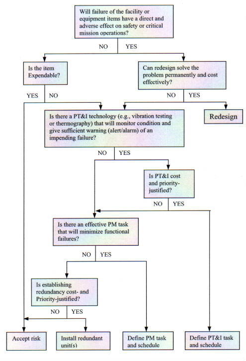 |
7.3.11. RCM is a living system. It gathers data from the results achieved and feeds this data back to improve design and future maintenance. This feedback is an important part of the Proactive Maintenance element of the RCM program.
7.4.1. Using RCM facilitates developing maintenance standards for ensuring, even in the procurement and installation phases, that a system meets its designed reliability or availability. RCM determines maintenance requirements by considering the following questions:
a. What does the system do? What is its function?
b. What failures are likely to occur?
c. What are the likely consequences of failure?
d. What can be done to reduce the probability of the failure, identify the onset of failure, or reduce the consequences of the failure?
7.4.2. Figure 7-1 provides a decision logic tree for use in an RCM analysis to determine the type of maintenance appropriate for a given maintainable facilities equipment item. Note that the logic as presented results in a decision in the bottom blocks concerning whether a particular piece of equipment should be reactively maintained ("Accept Risk" and "Install Redundant Units"), PM'ed ("Define PM Task and Schedule") or predictively maintained ("Define PT&I Task and Schedule").
Failure is the cessation of proper function or performance. RCM examines failure at several levels: the systems level, subsystem level, component level, and sometimes even the parts level. The maintenance approach must be based on a clear understanding of the consequences of failure at each level. For example, a failed lamp on a control panel may have little effect on overall system performance; However, several combined, minor components in degraded conditions, could collectively cause a failure of the entire system.
7.5.1. Identify the System Functions. This step involves examining the capability or purpose of the system. Some items, such as a circulating pump, perform an on-line function (constantly circulating a fluid); their operational state can be determined immediately. Other items, such as a sump pump, perform an off-line function (intermittently evacuating a fluid when its level rises); their condition can be ascertained only through an operational test or check. Functions may be active, such as pumping a fluid, or passive, such as containing a fluid. Also, functions may be hidden, in which case there is no immediate indication of a failure. This typically applies to an emergency or protective system such as a circuit breaker that operates only in case of a short circuit (electrical failure of another system or component).
7.5.2. Identify Failures. The proactive approach to maintenance analysis identifies potential system failures and ways to prevent them. It, along with human observations during normal operations or maintenance tasks, also identifies prefailure conditions that indicate when a failure is imminent. (The latter is a basis for selecting PT&I applications.) Figure 7-2 is a list of failure codes that may be used to identify by category recurring problems. These will provide a means of identifying areas, systems and equipment where root cause failure or other proactive analysis may be applied. The Computerized Maintenance Management System (CMMS) and work order form should include fields for failure codes in order to maintain historical data.
CATEGORY |
CODE | CATEGORY | CODE | CATEGORY |
CODE | ||
|---|---|---|---|---|---|---|---|
| Drain | DRAN | Power supply | PSPL | ||||
| Engine | ENGN | Pressure switch | PSWC | ||||
| Elevator | LVTR | Pulley | PULL | ||||
| EMCS | EMCS | Pump | PUMP | ||||
| Bearings | BRGS | Enclosure | NCLS | Regulator | RGLT | ||
| Belts | BLTS | Evaporator | EVAP | Rheostat | RSTT | ||
| Breaker | BRKR | Fastener | FSNR | Roof | ROOF | ||
| Cable, power | CABL | Filter | FLTR | Seal | SEAL | ||
| Capacitor | CPTR | Flashing | FLSH | Shell | SHLL | ||
| Commutator | CMTR | Fouled | FOUL | Shaft | SHFT | ||
| Compressor | CPRS | Gear | GEAR | Starter | STRT | ||
| Computer | CPTR | Generator | GNTR | Stator | STTR | ||
| Condenser | CNDN | Humidistat | HSTT | Support/base | SPPT | ||
| Connector | CNTR | Impeller | IMPL | Switch | SWCH | ||
| Controller | CNTL | Inductor | NDCT | Thermistor | THMS | ||
| Cooler, swamp | COLS | Light | LGHT | Timer | TMER | ||
| Cooling Coil | COIL | Logic, PLC | PLOG | Transformer | TRAN | ||
| Corrosion | CRSN | Lubrication | LUBE | Tube, boiler | TUBE | ||
| Coupling | CPLG | Meter | METR | Valve | VLVE | ||
| Crane | CRNE | Motor | MOTR | Winding | WNDG | ||
| Damper | DMPR | Packing | PCKG | Window | WIND | ||
| Dirt | DIRT | Pipe | PIPE | ||||
| Door, power | PDOR | Piston | PSTN |
7.5.3. Identify the Consequences of Failure. The most important consequence of failure is a threat to safety. Next is a threat to the environment or mission accomplishment (operating capability). The RCM analysis should pay close attention to the consequences of the failure of infrequently used, off-line equipment and hidden function failures. Also, it should consider the benefit (reduced consequences of a failure) of redundant systems.
7.5.4. Identify the Failure Process. Determining the methods and root causes of failures provides insight into ways to detect or avoid failures. The examination, which investigates the cause of the problem and not just its effect, should consider factors such as wear, overload, fatigue, or other processes.
7.5.5. Verify the System. Before efforts are expended on a system, it is important to verify that the system was installed or is being used as originally designed. This review of the design and Maintenance Support Information (MSI) may reveal the root cause of a past or anticipated problem. Although the existing design may have been correct, the installation, while functional, may have been improper or there may have been latent manufacturing defects. These deficiencies should be discovered and corrected by the contractor during the acceptance process, before the equipment is accepted by the Government and the contractor leaves the job site. If, after acceptance, the installation is still under warranty, the problem may be resolved without an additional expenditure of NASA resources. Changes in the intended use of equipment can also create problems leading to excessive wear and premature failure.
7.5.6. Modify the System. Redesigning the system to eliminate the weakness may be the most desirable solution since it can eliminate a potential cost. However, redesign may not be possible in many facilities maintenance situations.
7.5.7. Define the Maintenance Task. The following factors should be considered when defining the maintenance task:
a. Once it has been determined that the failure of a facility or equipment item will have a direct effect on the safety or mission operation and redesign cannot improve its reliability, then a PT&I, PM, or PGM task or combination of tasks should be identified that will lessen the chances or consequences of a failure. Where applicable, predictive technologies should be used to monitor the condition of the facility or equipment. If the technology or local expertise is not available, a preventive maintenance program is normally applicable.
b. Maintenance tasks can be time directed (e.g., every 8 weeks), condition directed (e.g., when pH is greater than 7.3), or inspection directed (e.g., if a component is found worn). A particular bearing can be monitored for vibration (PT&I), routinely lubricated and checked (PM), or replaced prior to its expected failure point (PGM).
c. The total system should be evaluated to ensure that all the individual tasks maintain the system at the same degree of reliability. The tasks should also be grouped to ensure that they can be executed in the most economical manner. This may be by multiple tasks on an individual equipment item or like tasks on numerous items of equipment in a given facility or zone of several facilities.
7.5.8. Install Redundant Unit(s). Situations exist where, despite all effective maintenance efforts, the risk of a potential failure is still unacceptable. Very critical areas such as a mission control or communication center may require uninterrupted facility equipment to maintain power or climatic control. The criticality may prelude even shutdown for maintenance purposes. In these situations, redundancy is justified and recommended. The problem may be corrected through additional distribution or switching of power or ventilation ducts, provided the system can accept the additional loads. The need for a redundant system should be determined before the situation becomes critical. This will preclude premature failure resulting from a lack of maintenance on a system that cannot be shut down. Often the loss to the mission would be of much greater cost than the redundant system. This need requires close coordination and communication with the customer.
7.5.9. Accept the Risk. It may be that further safety or environmental precautions are not possible or that the economic or operational cost of a failure is insignificant or substantially less than the cost of any effective redesign or maintenance procedure. In the former case, the accepted risk should be identified and quantified, and all parties concerned should be made aware of the risk and appropriate recovery procedures. In the latter situation, it does not make business sense to implement a PM or PGM task. This philosophy is known as "run-to-failure."
7.6.1. Safety. Per NPD 8700.1, NASA Policy for Safety and Mission Success, NASA policy is to ". . . Avoid loss of life, personal injury or illness, property loss or damage, or environmental harm from any of its activities and ensure safe and healthful conditions for persons working at or visiting NASA facilities . . . ." By its very features, including analysis, monitoring, taking decisive action on systems before they become problematic, and thorough documentation, RCM is highly supportive of and an integral part of the NASA safety policy.
7.6.2. Reliability. RCM places great emphasis on improving equipment reliability, principally through the feedback of maintenance experience and equipment condition data to facility planners, designers, facilities maintenance managers, craftsmen, and manufacturers. This information is instrumental in continually upgrading the specifications for equipment to provide increased reliability. The increased reliability that comes from RCM leads to fewer equipment failures and, therefore, greater availability for mission support and lower maintenance costs.
7.6.3. Cost. Due to the initial investment required in obtaining the technological tools, training and equipment condition baselines, a new RCM program typically results in a short-term increase in maintenance costs. This increase is relatively short lived. The cost of repair decreases as failures are prevented and preventive maintenance tasks are replaced by condition monitoring. The net effect is a reduction of both repair and a reduction in total maintenance cost. Often, energy savings are also realized from the use of PT&I techniques.
7.6.4. Scheduling. The ability of a condition-monitoring program to forecast maintenance provides time for planning, obtaining replacement parts and arranging environmental and operating conditions before the maintenance is done. PT&I eliminates unnecessary maintenance performed by a time-scheduled maintenance program which tends to be driven by the minimum "safe" intervals between maintenance tasks. Additionally, a principal advantage of RCM is that it obtains the maximum use from equipment. With RCM, equipment replacement is based on equipment condition - not on the calendar. This condition-based approach to maintenance thereby extends the operating life of the properly maintained facility and its equipment.
7.6.5. Efficiency/Productivity. Safety is the primary concern of RCM. The second most important concern is cost-effectiveness. Cost-effectiveness takes into consideration the priority or mission criticality and then matches a level of cost appropriate to that priority. The flexibility of the RCM approach to maintenance ensures that the proper type of maintenance is performed on equipment when it is needed. Maintenance that is not cost effective is identified and not performed.
7.7.1. The facilities life cycle is often divided into two broad stages, acquisition (planning, design, construction and acceptance) and operations. RCM affects all phases of the acquisition and operations stages to some degree, as shown in Table 7-1. Decisions made early in the acquisition cycle profoundly affect the life-cycle cost of a facility. Even though expenditures for plant and equipment may occur later during the acquisition process, their cost is committed at an early stage. As shown conceptually in Figure 7-3, planning (including conceptual design) fixes two-thirds of the facility's overall life-cycle costs. The subsequent design phase determines an additional 29 percent of the life-cycle cost, leaving only about 5 percent of the life-cycle cost that can be impacted by the later phases.
7.7.2. The decision to include a facility in the RCM program, including PT&I, is best made during the planning phase. As RCM decisions are made later in the life-cycle, it becomes more difficult to achieve the maximum possible benefit from the RCM program.
7.7.3. Even though maintenance is a relatively small portion of the overall life-cycle cost, 3 to 5 percent of a facility's operating cost, RCM is still capable of introducing significant savings during the Operations and Maintenance (O&M) phase of a facility's life. Savings of 30 to 50 percent in the annual maintenance budget are often obtained overtime through the implementation of a balanced RCM program.
Life-Cycle Phase |
Acquisition Implications |
Operations Implications |
|---|---|---|
| Planning |
Requirements Validation Contract Strategy RCM Implementation Strategy Funding Estimates Construction Equipment (Collateral/R&D) Labor Training Operations A&E Scope of Work | Requirements Development Modifications Alterations Upgrades A&E Scope of Work Funding Estimates O&M Considerations Annual Cost Labor Spare Parts |
| Design | A&E Selection Drawings Specifications Acceptance Testing Requirements | A&E Selection Drawings Specifications Acceptance Testing Requirements |
| Construction | Contractor Selection
Mobilization Construction Activation (R&D) | Contractor Selection
Construction Acceptance Testing |
| Acceptance | Equipment Acceptance and
Hand-off Establishing Baselines Contract Closeout | Equipment Acceptance and Hand-off Establishing Baselines Documentation |
| O&M | Not Applicable | RCM Operations Training/Certification |
An RCM program includes reactive, preventive, predictive and proactive maintenance. Refer to the NASA Reliability Centered Maintenance Guide for Facilities and Collateral Equipment for more in-depth information.
7.8.1. Reactive Maintenance. Reactive Maintenance also is referred to as breakdown, repair, fix-when-fail, or Run-to-Failure (RTF) maintenance. When applying this technique, maintenance, equipment repair or replacement occur only when the deterioration in an equipment's condition causes a functional failure. This type of maintenance assumes that failure is equally likely to occur in any part, component or system. Thus, this assumption precludes identifying a specific group of repair parts as being more necessary or desireable than others. If an item fails and repair parts are not available, delays ensue while parts are obtained. If certain parts are urgently needed to restore a critical machine or system to operation, a premium for expedited delivery must be paid.
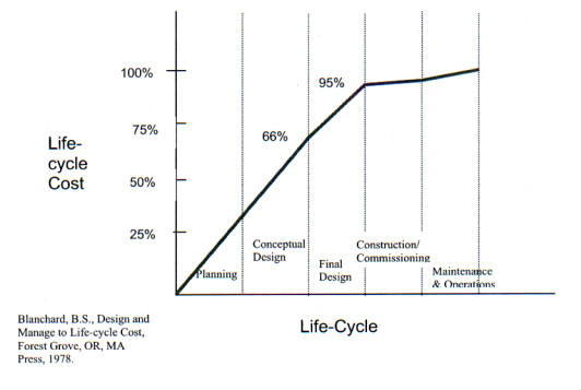 |
Also, there is no ability to influence when the failures occur because no (or minimal) action is taken to control or prevent them. When this is the sole type of maintenance practiced, a high percentage of unplanned maintenance activities, high replacement part inventories, and inefficient use of the maintenance effort typify this strategy. A purely reactive maintenance program ignores the many opportunities to influence equipment survivability. On the other hand, reactive maintenance can be used effectively when it is performed as a conscious decision based on the results of an RCM analysis that compares the risk and cost of failure with the cost of the maintenance required to mitigate that risk and the cost of failure. For example, periodic maintenance on a standard, inexpensive bathroom fan could not be cost-effective. Typically this type of fan would be run-to-failure and simply replaced at that time, since the cost of maintenance or repair would probably exceed the cost of a replacement fan. Table 7-2 suggests the criteria to be used in determining the priority for repairing or replacing the failed equipment in the reactive maintenance program.
7.8.2. Preventive Maintenance (PM). PM consists of regularly scheduled inspection, adjustments, cleaning, lubrication, parts replacement, calibration, and repair of components and equipment. It is performed without regard to equipment condition. PM schedules periodic inspection and maintenance at predefined intervals in an attempt to reduce equipment failures for susceptible equipment. As equipment ages the frequency and number of checkpoints may need to be reevaluated using the age exploration process. This is a process that uses PT&I and other methods to extend the period between PM tasks while maintaining equipment condition.
| Priority |
|---|
Number |
Description | Criteria Based on Consequences of Equipment/System Failure |
|---|---|---|
| 1 |
Emergency |
Safety of life or property threatened. Immediate serious impact on mission. |
| 2 |
Urgent |
Continuous facility operation threatened. Impending serious impact on mission. |
| 3 | Priority |
Degrades quality of mission support. Significant and adverse effect on project. |
| 4 | Routine | Redundancy available. Impact on mission insignificant. |
| 5 | Discretionary | Impact on mission negligible. Resources available |
| 6 | Deferred | Impact on mission negligible. Resources available |
This process can result in substantial maintenance savings. These savings are dependent on the PM intervals set, which can result in a significant decrease in inspection and routine maintenance; however, it should also reduce the frequency and seriousness of unplanned machine failures for components with defined, age-related wear patterns.
7.8.2.1. Traditional PM is keyed to failure rates and times between failures. It assumes that these variables can be determined statistically, and therefore one can replace a part due for failure before it fails. PM assumes that the overhaul of machinery by disassembly and replacement of worn parts restores the machine to like-new condition with no harmful side effects and that the new components are less likely to fail than the old components of the same design.
7.8.2.2. Failure rate, or its reciprocal, mean-time-between-failures, is often used as a guide to establishing the interval at which maintenance tasks should be performed. The major weakness in the application is that failure rate data determines only the average failure rate. In reality, failures are equally likely to occur at random times and with a frequency unrelated to the average failure rate. For some items, failure is not related to age, and consequently, timed maintenance can often result in unnecessary maintenance. PM can be costly and ineffective when it is the sole type of maintenance practiced.
7.8.3. Predictive Testing and Inspection (PT&I)
7.8.3.1. PT&I, also known as predictive maintenance or condition monitoring, uses primarily nonintrusive testing techniques, visual inspection, and performance data to assess machinery condition. It replaces arbitrarily timed maintenance tasks with maintenance that is scheduled only when warranted by equipment condition. Continuing analysis of equipment condition-monitoring data allows for the planning and scheduling of maintenance or repairs in advance of catastrophic and functional failure. Collected PT&I data is used for trend analysis, pattern recognition, data comparison, tests against limits and ranges, correlation of multiple technologies and statistical process analysis to determine the condition of the equipment and to identify the precursors of failure. PT&I does not lend itself to all types of equipment or possible failure modes and therefore should not be the sole type of maintenance practiced.
7.8.3.2. A variety of PT&I methods are used to assess the condition of systems and equipment. These technologies include intrusive and nonintrusive methods as well as the use of process parameters to determine overall equipment condition. The data acquired permits an assessment of the system or equipment performance degradation from the as-designed condition. The most common PT&I technologies, described in greater detail in Appendix E and the NASA Reliability Centered Maintenance Guide for Equipment and Collateral Equipment, are the following:
a. Vibration Analysis.
b. Lubricant and Wear Particle Analysis.
c. Thermal Imaging and Temperature Measurement.
d. Passive (Airborne) Ultrasonics.
e. Electrical Testing and Motor Current Analysis.
f. Flow Measurement and Leak Detection.
g. Valve Operation.
h. Corrosion Monitoring.
i. Process Parameters.
j. Visual Observations.
7.8.4. Proactive Maintenance
7.8.4.1. A Proactive maintenance program is the capstone of the RCM philosophy. Proactive maintenance improves maintenance through better design, installation, maintenance procedures, workmanship and scheduling. The eight most commonly recognized proactive techniques to extend machinery life, described in detail in the NASA Reliability Centered Maintenance Guide for Facilities and Collateral Equipment, are the following:
a. Specification for new/rebuilt equipment.
b. Precision rebuild and installation.
c. Failed-part analysis.
d. Root-cause failure analysis.
e. Reliability engineering.
f. Rebuild certification/verification.
g. Age exploration.
h. Recurrence control.
7.8.4.2. The characteristics of proactive maintenance are the following:
a. It uses feedback and communications to ensure that changes in design or procedures are promptly made available to designers and managers.
b. It employs a life-cycle view of maintenance and supporting functions.
c. It ensures that nothing affecting maintenance occurs in isolation.
d. It employs a continuous process of improvement.
e. It optimizes and tailors maintenance techniques and technologies to each application.
f. It integrates functions that support maintenance into maintenance program planning.
g. It uses root-cause failure analysis and predictive analysis to maximize maintenance effectiveness.
h. It adopts an ultimate goal of fixing equipment forever.
i. It periodically evaluates the technical content and performance interval of maintenance tasks (PM and PT&I).
.8.5. Implementing Proactive Maintenance
7.8.5.1. An additional critical step in implementing an effective proactive maintenance program is the design for maintainability process. Design for Maintainability was a NASA sponsored research project conducted by the Construction Industry Institute. Design for maintainability integrates facility operations and maintenance knowledge and experience at an early stage in the project delivery process. Incorporating maintainability concepts, including RCM, early in the life of a project, where influence potential is high, will result in the principal benefits of less rework, smoother startup and turn over, and less costly maintenance after project turn over. Design for Maintainability represents a method to formally incorporate proactive maintenance into construction projects. It will allow active participation of operation and maintenance staff in determining facility project design requirements and ensure these requirements are satisfied. Additional information on this concept is available from Construction Industry Institute publications.
7.8.5.2. A successful maintainability program will have the following attributes:
a. Corporate commitment.
b. Program support.
c. Maintainability planning.
d. Maintainability implementation.
e. Program updating.
7.8.5.3. The design for maintainability model process has six major milestones:
a. Management commitment to maintainability. Demonstrated through commitment of resources, development policies, and designating a maintainability champion.
b. Establishing a maintainability program. Demonstrated through development of a maintainability staff, procedures and a lessons learned database.
c. Obtaining maintainability capabilities. Demonstrated by establishing project level maintainability responsibility and developing resources for project maintainability reviews.
d. Planning Maintainability implementation. Demonstrated by forming project cross-functional teams, defining maintenance strategies and maintainability goals and integrating appropriate RCM technology.
e. Implementing maintainability. Demonstrated by conducting project maintainability meetings, applying maintainability concepts to design and construction, providing documentation and conducting maintenance training.
f. Updating the maintainability program. Demonstrated by evaluating program effectiveness and updating the process in the lessons learned database.
7.8.5.4. Within the ideal process milestones and the success attributes, maintainability must be accomplished through several different approaches applied individually or in combination. These approaches are:
a. Standard design practice.
b. Contract specifications, such as SPECSINTACT having appropriate maintainability and RCM clauses included.
c. Cross-functional project teams.
d. Pilot maintainability programs.
e. Integration of maintainability into existing project programs and processes.
f. Formal maintainability program.
g. Comprehensive tracking of lessons learned.
7.8.5.5. In summary, design for maintainability is the first step of an effective maintenance program, linking proactive maintenance and RCM goals to the design and construction process. If adequate measures for cost-effective maintainability are not integrated into the design and construction phases of a project, the risk increases that reliability will be adversely impacted and total life-cycle costs increase significantly. Appropriate levels of maintainability seldom occur by chance. It requires up front planning, setting objectives, disciplined design implementation, and feedback from prior projects. It is vital to identify critical maintainability and reliability issues and integrate them into facility project designs to achieve long term facility owning and operating benefits.
In addition to their applicability during the operations and maintenance phase of equipment life-cycle, RCM principles should be used in performing the facility Condition Assessments and in preparing the annual work plan; in establishing the Center's BMAR; during facilities planning, design, new construction, modification, equipment procurement and in the preparation of Architect and Engineering (A&E), construction, equipment procurement, and maintenance and operation contracts; in the acceptance testing of new or major-repaired equipment by the contractor during the acceptance process; and in the Quality Assurance of Performance-based Contracts. Appropriate RCM clauses and criteria should be included in all Requests for Proposals, Requests for Quotations (RFQ), and in the contracts themselves.
7.9.1. Facilities Condition Assessment (FCA). See also Chapters 4, Annual Work Plan, and 9, Backlog of Maintenance and Repair. RCM is valuable during the continuous FCA process. Individual system reliability and O&M costs and numbers of TC's, plotted over the equipment's service life, can be tracked by the CMMS. Equipment condition relative to other similar equipment can be tracked by reviewing the PT&I data and statistically trended in an excel spreadsheet. Similarly, other indices such as PT&I alarms and equipment availability can be tracked. The sum of all of this data will result in a rank ordering of the equipment in terms of condition, availability and cost to maintain the function.
7.9.2. Annual Work Plan . See also Chapter 4, Annual Work Plan, for a more detailed discussion. RCM principles, and particularly PM and PT&I, are integrated into the Center's maintenance program through the Annual- and 5-year Work Plans. These are required to develop PM and PT&I funding requirements for the next five years, including all labor, parts, materials and special tools. RCM will identify the most effective maintenance in terms of retaining the highest reliability at the lowest cost and include criticality codes based on mission support, condition code, specific inspections and maintenance tasks to be performed, equipment parameters, the estimated resources required, and specific instructions for obtaining condition assessment information as part of each maintainable collateral equipment PM/PT&I.
7.9.3. Backlog of Maintenance and Repair (BMAR). See also Chapter 9, Backlog of Maintenance and Repair, for a more detailed discussion. Facilities maintenance within NASA is absolutely crucial in ensuring facility availability for critical missions throughout the Agency and in NASA's stewardship of the Government facilities with which it is entrusted. The effect of reduced maintenance is not always felt immediately, and therefore, it is essential that Centers have sufficient management information available to plan long- and short-term maintenance requirements properly, recognize adverse funding trends, and be able to articulate the effect of reduced maintenance on facility availability and the mission. After the RCM process is used to identify facility and equipment availability and condition deficiencies, the BMAR identifies to higher authority, i.e., OMB and Congress, unfunded facilities maintenance work for those items necessary to support the Center mission and the consequences of nonfunding.
7.9.4. SPECSINTACT
7.9.4.1. Early in the planning of a new facility, consideration must be given to the extent RCM analysis and PT&I techniques will be used to maintain the facility and equipment. The fundamental determination is the amount of built-in condition monitoring, data transfer, and sensor connections to be used. It is more economical to install this monitoring equipment and connection cabling during construction than later. Planning, designing and building in the condition monitoring capability ensures that it will be available for the units to be monitored. Continuously monitored equipment tied into performance analyzers permits the monitoring of its function and signs of any degradation. Installed systems also reduce manpower requirements relative to obtaining the data manually.
7.9.4.2. NASA has integrated RCM principles into its standard construction specifications, SPECSINTACT. The emphasis is to design new equipment with a high degree of reliability, at the lowest reasonable cost, that provides improved maintainability and ease of monitoring. Maintainability and monitoring factors that should be considered by the designer include the following:
a. Access. Equipment, its components, and facilities should be accessible for maintenance. There should be clear access to collect equipment condition data with portable data loggers or fluid sample bottles.
b. Material. Materials must be chosen for durability, ease of maintenance, availability and value.
c. Standardization. Use of special or one-of-a-kind materials, fittings or fixtures is to be minimized and the use of common equipment component parts maximized. Standard equipment that can have multiple uses should be selected, where feasible.
d. Quantitative Maintenance Goals. Quantitative measures of maintenance (such as Mean-Time-Between-Maintenance (MTBM) and maintenance downtime) should be used during design to set maintainability goals.
e. On-line Data Collection. Installed data collection sensors and links may be justified for high priority, high cost equipment or inaccessible equipment.
f. Management Indicators. Management indicators and the analysis method should be incorporated into the system design. Often the performance parameters monitored for equipment or system control may be used to monitor equipment condition.
g. Performance Measures. RCM performance measures such as operating time or equipment loading are directly equipment related. The data to be used and the collection method are incorporated into the system design.
7.9.5. Acceptance. See also Chapter 8, Reliability Centered Building and Equipment Acceptance, for a more detailed discussion. In today's tight budget environment for facilities operations and maintenance, there is great advantage to NASA in using the construction contractor's quality control function, prior to the contractor's receipt of final payment and exit from the job site, to perform noninvasive diagnostic tests (PT&I) to verify that there are no latent manufacturing defects and the quality of the installation of newly installed equipment.
7.9.6. Performance-based Contract Monitoring. See also Chapter 12, Contract Support, for a more detailed discussion. Performance-based Contract and outcome monitoring require the contractor to meet specific standards of performance. These are often based on metrics and indicators that are derived from RCM principles and obtained through PT&I technologies. Percent (%) availability, for example, is a performance metric that is compared to a standard set by the Center based on baseline data obtained at the time of equipment acceptance or during RCM analysis. Further, the degree of QA required of the Government is dependent not only on the contractor's performance, but also on the RCM criticality codes applied to each facility and equipment. PT&I techniques may be prescribed in the Government's formal QA Plan as methods used to inspect the contractor's work and RCM analysis may be used by the QAE to observe overall trends. For example, trends identifying increased TC's or downtime for specific units of equipment may be indicative of a lack of preventive maintenance that the contractor is obligated to perform.
a. During the course of new construction, major repair, or rehabilitation of facilities, it is not unusual to discover installed systems or equipment that are out of alignment and balance, that contain latent defects from manufacturing and installation, or that simply do not operate as intended. For example, evaluations of new construction of at least two NASA Centers revealed that 85- to 100-percent of the rotating equipment was misaligned, out-of-balance, or contained defective bearings. These types of systems or equipment defects result in premature failures, which require unbudgeted corrective action by O&M staff. Given today's tight facilities O&M budgets, each Center should, for new construction, major repair, or rehabilitation of facility projects, employ an acceptance process that includes the use of PT&I to verify system and equipment condition. This should be done prior to acceptance of the work and the contractor's departure from the job site and turning the keys over to the operations and maintenance staff. The expected end result is a facility that is safer and is less costly to maintain. The acceptance process can achieve these results by:
(1) Ensuring there are no latent factory or installation defects;
(2) Verifying building systems and equipment performance through functional performance testing; and
(3) Providing full documentation and training for the O&M staff to improve their performance.
b. Building and equipment acceptance is one element of a larger, more comprehensive construction quality program known as "Commissioning". Currently, there are three variations of commissioning being practiced - Traditional Commissioning, Total Building Commissioning and NASA's customized application of a portion of Commissioning called Reliability Centered Building and Equipment Acceptance.
8.1.1. Traditional Commissioning. Traditional Commissioning involves performing random tests and checks on facility systems to ensure that they are properly balanced, functionally operational and comply with the design intent. It systematically checks operating parameters such as pressure, temperature, minimum and maximum air flow, lighting levels, electrical amperage and voltage, torque, fluid volumes, and other thermodynamic measures at key locations, as well as balanced conditions. It is a method of acceptance testing that, when performed on a random basis at random sampling points, checks to ensure that the outcome indices at those points are in compliance with the outcome requirements stated in the design specification. Although the method ensures that the installation meets the design requirements, Traditional Commissioning reflects the conditions in a snapshot in time, specifically on the day(s) that the system is being inspected for acceptance. Also, it generally fails to emphasize the quality of the equipment installation itself, such as latent manufacturing and installation defects. Even if the installation is in compliance with the design and reflects the proper process parameters at the time of equipment acceptance, these undetected defects may result in premature equipment failure and operational and maintenance headaches due to misalignment or similar condition discovered at a later date. The problem then becomes one of many warranty issues, which based on past, typical NASA history, often are inadequately enforced.
8.1.2. Total Building Commissioning. Total Building Commissioning is a cradle-to-grave systematic process of ensuring that facility systems are planned, designed, installed, tested, and capable of being operated and maintained to perform according to the design intent and the user's needs. The Total Commissioning process is optimally applied to all phases of a construction project - program planning, design, construction/installation, acceptance and postacceptance/ occupancy. Commissioning team involvement begins at the earliest stages of project planning, where its expertise in such areas as system sizing, code compliance, maintainability, user friendliness, product quality and reliability, ergonomics and projected life-cycle costs, is applied to the design. The commissioning staff is also involved in monitoring the quality of the construction in terms of workmanship and specification and code compliance throughout the construction, using Traditional Commissioning tests and inspection procedures for quality assurance and for system acceptance. Finally, the quality team monitors the installed system following acceptance to ensure that there are no latent installation defects or degradation of system performance and operational quality. This rigorous commissioning process is intended to provide the following benefits:
a. Ensure that a new facility begins its life with systems at optimal productivity.
b. Improve the likelihood that the facility will maintain this level of performance.
c. Restore an existing facility to high productivity.
d. Ensure facility renovations and equipment upgrades function as designed.
8.1.3. NASA's Building and Equipment Acceptance. NASA's application of Commissioning is a customization of a portion of the Traditional and Total Commissioning processes that NASA calls Reliability Centered Building and Equipment Acceptance. NASA recognizes there can be substantial benefit even when commissioning concepts are applied only to the acceptance phase of a construction project. These benefits can be gained during acceptance by using available PT&I technologies in addition to traditional operational parameters to identify latent manufacturing, shipping, and installation induced defects. Identifying and correcting these defects can reduce premature failures, increase safety and reliability and decrease life-cycle costs. NASA's portion of the Commissioning concept concentrates on facility and equipment acceptance rather than on Total Commissioning's cradle to grave detailed oversight and evaluations because of the following:
a. NASA's placing safety as a top priority.
b. The current Federal budget process involving project funding from numerous autonomous and nonintegratable sources
c. NASA's emphasis on reducing life-cycle costs within available and limited resources.
d. The institution of a strong and vibrant RCM program in place Agencywide.
8.1.4. Many of the problems, safety concerns and associated costs inherited during the O&M phase are the result of i nadequate or nonexistent standards and procedures for equipment acceptance. Thus, the focus of NASA's equipment acceptance is on ensuring that the contractor detects latent manufacturing and installation defects through an effective quality control program before final acceptance of the installation by the Government.
8.1.5. This chapter provides a brief overview of NASA's Acceptance program. Refer to the NASA Reliability Centered Building and Equipment Acceptance Guide for more detailed information and extensive discussion of the subject.
The RCM approach takes a life-cycle view of facilities and collateral equipment and seeks to ensure that facilities and collateral equipment are properly built and installed in order to reduce the probability of premature failure. A key element in the transition from good design to full operation is the construction and acceptance phase.
8.2.1. Initial Planning and Design. The long-term reliability of an installation or refurbishment begins with the initial planning and design. The initial criteria and equipment design determines the inherent equipment reliability, maintainability, and supportability. Moreover, as discussed in Chapter 7, Reliability Centered Maintenance, about 95 percent of the total equipment cost is determined by the end of the planning and design phase. Even though expenditures for plant and equipment may occur later during the acquisition process, their cost is committed at an early stage. The decision to include a facility in the RCM program, including PT&I, is best made during the planning phase. As RCM decisions are made later in the life cycle, it becomes more difficult to achieve the maximum possible benefit from the RCM program. It has been estimated by NASA facilities and collateral equipment designers that the cost to make a system change, once the system is built, is anywhere from 10 to 1,000 times more than if the change was incorporated during the system design. Clearly, the planning and design phase of facilities and collateral equipment life cycle is the time to focus on the ability to sustain operation through the use of effective acceptance testing, proper trending, necessary maintenance, and the performance of timely repair, when needed.
8.2.2. Construction and Acceptance. Contracts for construction work at NASA Centers shall require contractor responsibility for an adequate quality control program in place for the proper installation of the facility and equipment in accordance with the design requirements. Throughout the installation and at the time of acceptance, PT&I must be performed to verify that not only is the installation acceptable, i.e., that there are no latent factory or installation defects, but also that the required baselines are established. Consequently, any contractor performing work at NASA centers must have an understanding of the RCM process and how it affects the project. NASA contracts shall require the contractor to use personnel who are trained and certified in the appropriate PT&I technologies for acceptance testing to ensure that the results are accurate and consistent. The Center's Construction Manager is responsible for ensuring that all interim testing is performed and that the results meet the specifications and are documented and included with the final acceptance documentation. It is the Construction Manager's responsibility to ensure that the acceptance testing has been performed and to determine if the acceptance testing results are within the required tolerances. When all acceptance criteria have been met, the final responsibility of the Construction Manager is to collect all of the required documentation, including all manufacturers manuals, drawing redlines, and all acceptance testing data, and deliver it to the appropriate Center operations and maintenance personnel.
8.2.3. Maintenance and Operations. Even though maintenance is a relatively small portion of the overall life-cycle cost, 3 to 5 percent of a facility's operating cost, RCM is still capable of introducing significant savings during the Maintenance and Operations phase of a facility's life. Savings of 30 to 50 percent in the annual maintenance budget are often obtained through the introduction of a balanced RCM program. O&M personnel are ultimately responsible for the proper operation and maintenance of systems and equipment. However, how the facility and its equipment will be operated and maintained must be considered during the planning, design, and construction phases. During these phases, maintenance and operations needs are best served by carefully and realistically identifying and defining the PT&I and PM requirements. Although the performance of maintenance and operations occurs during the operations stage of the life cycle, some preparatory activities can be carried out during the acceptance stage. These activities can include O&M personnel selection, training requirements, procedure preparation, review of specifications, and the collection of baseline condition monitoring data from the Construction Manager. Refer to Chapter 7, Reliability Centered Maintenance, of this document and to the NASA Reliability Centered Maintenance Guide for Facilities and Collateral Equipment for guidance on the use of RCM during facilities operations and maintenance.
8.3.1. After construction is complete, it is important to verify that the systems and equipment are operating in accordance with the construction specifications. NASA's contracts shall accomplish this by requiring the contractor to verify, as an element of the contractor's quality control program, that the equipment specified is properly installed in accordance with design and local codes and standards, that there are no latent manufacturing or installation defects, and that individual and integrated systems and equipment operation is in accordance with the design intent. During NASA's acceptance process, individual equipment is acceptance-tested using PT&I, that focuses on equipment performance, and by traditional thermodynamic testing. By providing this initial baseline data for comparisons and trending it allows for the planning and scheduling of PM or repairs in advance of failure.
8.3.2. Facilities contain a myriad of equipment and systems, from the simplest light switch to a computer-controlled air conditioning system. While, all equipment can benefit from the reliability centered acceptance process it must be understood that even though an acceptance test is available, it is not always cost effective to perform. The decision to perform reliability centered acceptance should be based on the RCM techniques in the NASA RCM Guide for Facilities and Collateral Equipment and the NASA Reliability Centered Building and Equipment reliability centered Acceptance Guide.
8.3.3. Table 8-1 indicates the most appropriate and commonly used PT&I technologies with respect to the most common acceptance testing applications. These PT&I tests have become some of the most effective methods for testing new and in-service equipment for hidden defects.
8.3.4. Preliminary and final acceptance testing and documentation of the test results is to be performed by the contractor as part of the contractor's Quality Control program. The contractor must correct all detected deficiencies, and the condition monitoring data shall be retaken prior to acceptance of the facility and/or equipment by NASA. The NASA Center must observe and monitor this condition testing, analysis and documentation as part of its Quality Assurance program and ensure that the contractor provides all preliminary and final condition monitoring and analysis data to the Construction Manager.
The acceptance scope includes but is not limited to the following:
a. Documenting the design intent. Verifying that equipment and systems have been properly installed in accordance with the contract documentation and the manufacturer's written installation instructions.
b. Verifying the performance of each piece of equipment and each system, documenting the equipment and system performance and ensuring that there are no latent manufacturing and installation defects.
c. Verifying that equipment has been placed into operation with the manufacturer's observation and/or approval.
d. Verifying that adjusting, balancing and system testing has been properly performed.
e. Assembling and submitting record drawings
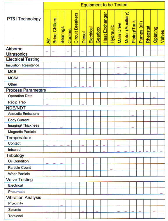 |
f. Training Center and/or the User's personnel in the proper operation of each piece of equipment and each system.
g. Documenting warranty start and end dates.
h. Assembling and submitting all records of Code authority inspections and approvals.
i. Validating the accessibility of all work relative to the maintenance requirements of each piece of equipment and promptly advising NASA of items of noncompliance.
j. Identifying, documenting and reporting all deficiencies of the work relative to the contract documents for tracking and correction through a deficiency-tracking program.
8.5.1. Roofs. Roofs are normally constructed layer by layer and comprised of many different types of materials. Moisture must not be allowed to enter the roof structure or materials during the construction phase, as any trapped moisture will eventually degrade the roof and structure and can cause a premature failure of the roofing system. Whereas traditional roof inspections usually look for the effects of leaks, infrared thermography should be used to look for wet insulation caused by water ingress during construction, improper installation or roof boundary failures.
8.5.2. Insulation/Building Envelope. Building insulation is installed during construction but in most cases, prior to the building being completed. Consequently, acceptance inspections must occur before the walls and ceilings are completed. On completion of the insulation installation a construction detail showing the insulation material type, amount, and location must be generated and submitted by the contractor. This information shall be forwarded to the appropriate RCM official for inclusion in the maintenance database. Infrared Thermography or ultrasonic mapping should be used during acceptance to identify insulation voids, insulation settling, and areas of moisture intrusion.
8.5.3. Piping Systems. Industry standard acceptance tests for water, plumbing and air systems first require a pressure test of all piping and fittings. During this test an ultrasonic scan should be performed on all accessible aboveground piping to help discover any leaks. For hot water systems, after the pressure and hydro tests are completed, and after piping insulation has been installed, the system should be charged with hot water and an infrared scan be performed to verify insulation integrity. For steam systems, ultrasonic scans should be performed on steam traps.
8.5.4. Mechanical Systems
8.5.4.1. Vibration Analysis. Analysis of system and equipment vibration levels is one of the most commonly used PT&I techniques to determine the condition of the rotating equipment and its structural stability in a system. It will detect deficiencies associated with wear, imbalance, misalignment, mechanical looseness, bearing damage, belt flaws, sheave and pulley flaws, gear damage, flow turbulence, cavitation, structural resonance and fatigue. Vibration measurements in the acceptance process must be performed by technically qualified persons, trained, experienced and certified in vibration measurement and be taken under specified operating conditions. Test documentation, including machine layout drawings indicating vibration measurement locations, must be submitted and validated and signed by the NASA construction manager or other authorized official prior to final equipment acceptance.
8.5.4.2. Balance. Only 10- to 20-percent of rolling element bearings achieve their design life. Premature bearing failure is frequently caused by excessive vibration caused by imbalance and misalignment. Acceptance testing for precision balance by the contractor at the time of equipment acceptance of motor rotors, pump impellers and fans is one of the most critical and cost effective techniques for achieving increased bearing life and resultant equipment reliability. NASA contracts shall require that balance measurements be performed by a technically qualified person trained, experienced and certified in machinery balancing.
8.5.4.3. Alignment. The forces of vibration from misalignment cause gradual deterioration of seals, couplings, bearings, drive windings and other rotating elements where close tolerances exist. The use of precision equipment and methods, such as reverse dial and laser systems to bring alignment tolerances within precision standards, by the contractor at the time of acceptance is necessary. Precision alignment will increase the average bearing life, decrease maintenance costs, and increase machinery availability.
8.5.4.4. Lubrication and Hydraulic Fluids. Lubricating and hydraulic fluid analysis is performed during acceptance for three reasons: to determine the machine mechanical wear condition; to determine the fluid condition; and to determine if the fluid has become contaminated. There is a wide variety of tests to provide information on these, usually packaged by independent testing laboratories to address all three areas. In addition to assessing the condition of the fluids at the time of equipment acceptance, these tests are necessary to provide a baseline for future RCM actions.
8.5.4.5. Ultrasonic Testing. Airborne ultrasonics is used by the contractor during equipment acceptance to hear noises associated with leaks, corona discharges, and other high frequency events. In addition to evaluating heat exchangers, ultrasonics can be used to verify boiler casing and associated piping integrity and the proper operation of steam traps.
8.5.4.6. Infrared Imaging. See paragraph 8.5.5.1, Infrared Imaging.
8.5.5. Electrical Systems
8.5.5.1. Infrared Imaging. Infrared Thermography (IRT) is a noncontact technique used during acceptance to identify hot and cold spots in energized electrical equipment, large surface areas such as boilers and building walls, and other areas where "stand off" temperature measurements is necessary. More specifically, IRT is used to detect faulty conditions in transformers, motor control centers, switchgear, substations, switchyards and power lines. In mechanical systems, IRT is used to identify blocked flow conditions in heat exchangers, condensers, transformer-cooling radiators and pipes and to verify fluid levels in large containers such as fuel storage tanks. Paragraphs 8.5.1. through 8.5.3. discuss IRT's applications specific to structural systems.
8.5.5.2. Power Factor Testing. Providing the optimum power factor maximizes the efficient use of electrical power. Power Factor, sometimes referred to as dissipation factor, is the measure of the power loss through the insulation system to ground. It is a dimensionless ratio that is expressed in percent of the resistive current flowing through an insulation to the total current flowing. Consequently, the power factor test is used for making routine comparisons of the condition of an insulation system and for acceptance testing to verify the equipment was manufactured and installed properly. The test is nondestructive, and regular maintenance testing will not deteriorate or damage insulation. Its most frequent applications are with electric motors, circuit breakers, motor control centers, switchgear, and transformers.
8.5.5.3. Insulation Resistance Testing. An insulation resistance test is a nondestructive Direct Current (DC) test used during acceptance to determine the condition of the of insulation of electrical systems. It indicates that the insulation under test can withstand the voltage being applied. The insulation resistance is generally accepted as a reliable indication of the presence of contamination or degradation. Its most frequent applications are with motors, switchgear, motor control centers, circuit breakers and transformers.
8.5.5.4. Insulation Oil Testing. High and medium voltage transformers, some high and medium voltage breakers, and some medium voltage switches are supplied with mineral oil as an insulation medium. Performing oil tests prior to turnover is needed to ensure that proper oil is installed and that the necessary inhibitors have been added. Further, when insulation systems are subjected to stresses, such as fault currents and overheating, combustible gas generation can change dramatically. In most cases these stresses can be detected early on; the presence and quantity of the individual gases can be measured and the results analyzed to indicate the probable cause of generation.
8.5.5.5. Motor Circuit Evaluation (MCE) and Motor Circuit Analysis (MCA). MCE is used during acceptance to evaluate the condition of motor power circuits. Any impedance imbalances in a motor will result in a voltage imbalance. Voltage imbalances in turn will result in higher operating current and temperatures, which will weaken the . insulation and shorten the motor's life. MCA is a method of detecting the presence of broken or cracked rotor bars or high resistance connections in end rings. While MCA is an effective test on in-service motors it is not generally used for acceptance testing. It is, however, normally performed at initial startup so a baseline can be established.8.5.5.6. Battery Impedance Testing. As a battery ages and begins to lose capacity, its internal impedance rises. This is a parameter that can be trended, comparing the current value with the original value, taken at acceptance, with previous readings, and with other identical batteries in the same battery bank. Additionally, battery impedance testing will indicate the existence of an internal short in the battery, of an open circuit in the battery, and premature aging due to excessive heat or discharges. There are no set guidelines and limits for this test. Each type, style, and configuration of battery will have its own impedance so it is important to take these measurements during acceptance to establish a baseline.
8.5.5.7. Airborne Ultrasonics. Deficiencies in electrical systems, such as corona discharges, loose switch connections, and internal arcing in deadfront electrical connections can all be discovered during acceptance using ultrasonic test devices. Corona discharge is normally associated with high voltage distribution systems and is produced as a result of a poor connection or insulation problem. The discharges generally occur at random, are the precursor to a failure, and are in the ultraviolet region and not normally detectable using thermography.
Acceptance data is to be recorded on a formal Acceptance Date Sheet and provided to the Center Construction Manager as part of the facility or equipment documentation package. A separate sheet must be filled out for each equipment unit being evaluated during the acceptance process and may result in a voluminous total package. Refer to the NASA Reliability Centered Building and Equipment Acceptance Guide for Acceptance Date Sheet samples.
This chapter discusses the BMAR. See also the related discussions in Chapter 4, Annual Work Plan, and on Facility Condition Assessment (Chapter 10, Facilities Maintenance Standards and Actions). BMAR has become the topic of renewed interest, concern and scrutiny within the highest levels of the Federal Government, including the U.S. Congress, Office of Management and Budget (OMB), Department of Defense and the Department of the Treasury.
9.1.1. Definition. The BMAR also referred to by the Federal Accounting Standards Advisory Board, Standard #6, as "deferred maintenance," is the total of essential, but unfunded facilities maintenance work necessary to bring Centers to the required facilities maintenance standards. It is work that should be accomplished during the year but cannot be accomplished within available resources. It does not include new construction, additions, or modifications. BMAR does include unfunded maintenance requirements, repairs, Replacement of Obsolete Items (ROI) and Construction of Facilities (CoF) repair projects.
9.1.2. BMAR, when applied correctly, can be an excellent overall indicator of the condition of Center facilities and collateral equipment as a group. It reflects the cumulative effects of underfunding facilities maintenance and repair. Review of BMAR trends and comparison of BMAR with the Current Replacement Value (CRV) and facilities maintenance funding provide indications of the adequacy of the resources devoted to facilities maintenance.
9.2.1. Inadequate funding for maintenance and repair programs throughout the federal government has historically been a standing problem. Agencies' needs have gotten little sympathy from the highest levels of Government for several reasons, including the following:
a. There is the tacit assumption that maintenance can always be put off for a month, a year, or even five years in favor of current operations with higher visibility and perceived better payback on the investment;
b. The Federal Government decision making authority for maintenance and repair programs is widely dispersed and is not structured in a manner that properly places accountability and responsibility for the care of facilities on a specific steward;
c. The relationship of facilities to Agency missions has not been recognized adequately in federal strategic planning and budgeting process;
d. Definitions and calculations of facilities-related budget items, methodologies for developing budgets, and accounting and reporting systems for tracking and repair expenditures vary. A concern is that inappropriate items have been included in the maintenance backlog to inflate the overall estimate as justification for a higher budget appropriation;
e. Agencies have not satisfactorily convinced higher authority about the implications of deferral that funds invested in preventive and timely maintenance will be cost effective, will protect the quality and functionality of the facilities, and will protect the taxpayer's investment.
9.2.2. All of these are indicative of the reasons why good, convincing, standardized and accurate data, presented in an organized and meaningful way, is so important to NASA in obtaining the budget appropriations necessary to maintain its facilities so that they operate adequately and cost effectively, their functionality and quality are preserved, and they provide a safe, healthy productive environment for the people who work and visit them every day. Further, as the steward of the facilities under its custody, NASA and by extension, each Center, has an obligation to the public to realistically and truthfully report its critical unfunded maintenance requirements and impact on mission. The BMAR is the vehicle by which that is done.
9.3.1. Most constructed facilities are designed to provide at least a minimum acceptable level of shelter and service for 30 years. With proper management and maintenance, buildings may perform adequately for 40 to 100 years or more and may serve several different functions.
9.3.2. The service life of a facility depends on many factors such as the quality of the building's design, the durability of the construction materials and component systems, the incorporated technology, the location and climate, the use and intensity of use, and damage caused by human error and acts of God. These all influence how well and how quickly a facility ages and the amount of maintenance and repair it requires over its life-cycle. Although a building's performance inevitably declines because of aging, wear and tear and functional changes, its service life can be optimized through adequate and timely maintenance and repairs, as illustrated in Figure 9-1. Conversely, when maintenance and repair activities are continuously deferred, the result can be an irreversible loss of service life.
9.3.3. Facilities that are functionally obsolete, are not needed to support NASA's mission, are not historically significant and are not suitable for transfer or adaptive reuse should be eliminated when it is cost effective to do so.
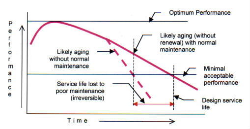
|
To be credible, the BMAR should be calculated on the basis of a condition assessment of all facilities as follows:
a. All maintenance deficiencies should be identified and cost-estimated based on a current facilities condition assessment that includes input from continuous inspections.
b. Deficiencies that will be corrected as part of the current year Annual Work Plan (AWP) must be subtracted from the BMAR.
c. Deficiencies in facilities that do not support the Center's long-term or near-term mission goals as articulated in the Master Plan are not be included in the BMAR.
d. The BMAR must be reevaluated annually. This not only authenticates the work that continues to be deferred as BMAR, but it also identifies work items in the BMAR covering deficiencies that have progressed to the point where they absolutely need to be included in the AWP.
9.5.1. There is no single, agreed upon guideline that determines how much funding is required to adequately maintain facilities. However, in 1990 the National Research Council recommended (Appendix B, resource 35) that, "An appropriate budget allocation for routine Maintenance and Repair (M&R) for a substantial inventory of facilities will typically be in the range of 2- to 4-percent of the aggregate current replacement value of those facilities."
9.5.2. Lacking an actual requirements-driven budget, the annual facilities maintenance budget should average 2- to 4-percent of CRV. (see Figure 2-1.) However, this rule of thumb applies only when the facilities have reached a steady-state maintenance condition (i.e., when the backlog has been reduced to an acceptable level). What an acceptable level is depends upon the nature of the backlog and the mission of the Center. For example, a large backlog for interior painting may be acceptable, while a large backlog of roof repairs may portend serious problems and should be reduced quickly.
9.5.3. Figure 9-2 illustrates the relationship between the backlog and annual maintenance funding levels as a percentage of CRV. It shows also a method of backlog reduction. For illustrative purposes only, Figure 9-2 assumes that 3.5-percent is the optimum steady-
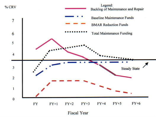 |
state maintenance funding level and that a backlog under 2-percent of CRV is acceptable. In this example, annual maintenance funding initially averages 2-percent of CRV, and the backlog is increasing each year. Then, baseline annual maintenance funding increases to .5 percent over a 2-year period, and additional funding is programmed for backlog reduction over a 6-year period. As the backlog is reduced to below 2-percent of CRV, special funding for backlog reduction decreases, but baseline maintenance funding remains at 3.5 percent. If the backlog begins to increase, maintenance funding should be increased again to reduce the backlog to below 2-percent of the CRV.
9.5.4. Metrics. Evaluation of BMAR and other maintenance performance indicators against a baseline is discussed in paragraph 3.11, Management Indicators, and listed in Appendix F. For example, in ratio 3 of Table 3-3 the trend should be downward, toward the NASA goal of reducing BMAR to a manageable level. An elimination of the BMAR is not always possible or desirable since BMAR can provide an ability to balance resources in the long term. Appendix F lists other metrics of which BMAR is a factor.
9.6.1. See also Chapter 10, Facilities Maintenance Standards and Actions, for more detailed discussion. Maintenance and repair requirements and equipment condition should be determined and validated through the facility condition assessment process. This assessment should be conducted continuously during normal PM and PT&I inspections, observations by the facility manager or other responsible individuals, and other work order repairs. It is important for the FCA process to focus on what is really important - on mission; life, health and safety issues; and on systems most critical to a facility's performance - in order to optimize available resources, provide timely and accurate data for formulating maintenance and repair budgets, and provide critical information for the ongoing management of facilities.
9.6.2. BMAR is a direct product of the FCA. NASA Centers are responsible for identifying and quantifying facility conditions in order to support annual and 5-year Work Plans. The BMAR is the delta between the work requirements identified in the FCA and those that can be satisfied within the funding available. Adoption of the RCM philosophy, PT&I, CMMS, and proactive maintenance approaches provide Centers with information related to facility condition that was not previously available. These new information sources, coupled with increased customer and user input, have the potential to provide valuable FCA data without having to perform many of the discrete inspections required under the traditional FCA processes.
9.6.3. NPD 8831.1 requires that Centers continuously assess facility conditions to identify and quantify their BMAR so as to be 80-percent accurate at any point in time. Since a Center's facilities are in a constant state of change due to normal wear and tear, renewal tasks, and reconfiguration, the FCA process must be dynamic if an accurate estimate of a Center's condition is to be obtained. In order to facilitate this all BMAR should be maintained in the Center's CMMS in a format that can be updated with the results of the continuous inspection program and with additions to and deletions from the facilities and equipment inventory. The CMMS records should identify BMAR by facility and classify each item as Mission Direct support, Mission Support, or Center Support and further classify each item by the type of work, such as roofs, HVAC systems, structures, roads, or similar system.
Each Center should develop a customized, written plan explaining how each of the following elements of the BMAR is to be performed. Its purpose is to standardize, organize, document and give credibility to the process.
9.7.1. BMAR Recording. As discussed above, the FCA is to be 80-percent accurate at any point in time. The unfunded requirements compose the BMAR database, which should be an element of the CMMS. As part of the continuous inspection process, the FCA should be periodically updated, and as new unfunded projects are developed to satisfy these deficiencies, they should be added to the BMAR listing in the CMMS. It is also important that key management information, such as facility number, equipment number, condition code, and criticality code, is linked to each BMAR requirement.
9.7.2. BMAR Inspection. FCA inspections are to be conducted on all maintainable facilities, structures, utilities and their collateral equipment on a continuous basis as part of the PM and PT&I inspections. All work orders should have a section where the craftsman can comment on the condition of the item being inspected or worked on. Existing real-time condition information, such as condition code, TC history, downtime information and BMAR information relevant to the equipment being inspected should be available to the craftsman before going to the site. Any changes in the condition (i.e., condition code) following the maintenance or repair action should then be noted as an update to the FCA and CMMS long term database.
9.7.3. BMAR Databases, Computer Systems, and Data Format. The BMAR database can be resident on the CMMS or a database that is linked to the CMMS. The same capability will exist in either case. BMAR projects should be identified as such in the database.
9.7.4. BMAR Costing Methods. A NASA wide cost effective procedure for estimating a Center's BMAR is being developed and will be provided as soon as available. Until a standard NASA method is developed one of the three methods shown in Appendix H may be used. Regardless of the BMAR costing method used, resources should not be expended to prepare engineering type cost estimates since "Ball Park" estimates will suffice.
9.7.5. Annual Changes to the BMAR Program. BMAR projects should be reviewed for currency, accuracy and relative priority at least once per year, prior to submission of the budget and CoF requirements. Once funding levels are determined for the upcoming fiscal year, the remaining projects and usually any new requirements are carried over to the next budget cycle and evaluated for funding for the next fiscal year. As BMAR requirements, including CoF projects, are funded they are to be removed from the unfunded list.
9.7.6. Annual BMAR Cost Updates. BMAR cost estimates are to be updated annually to account for inflation and any changed conditions based on project reviews. The inflation update can be made automatically by the computer.
Maintenance standards provide the basic information that identifies what portions of the inventory receive maintenance and to what level they are to be maintained. They also provide the benchmarks for conducting condition assessments and estimating workload. This chapter discusses maintenance standards in detail. Chapter 3 paragraph 3.12, Management Analysis, discusses the use of metrics and benchmarking in setting and updating maintenance standards.
10.2.1. Centers should use generally accepted facilities maintenance standards, as detailed in this procedures guide and the references contained in Appendix B, appropriate for the NASA objective of providing facilities to support safe, "world class" research and operations. The standards, which form a part of the PM programming, should be the basis for evaluating the condition of the facilities and for determining the minimum and desired material condition of facilities and collateral equipment. Centers should develop and use maintenance cycles that take into account the level of local use and environmental conditions.
10.2.2. In addition to the facilities maintenance standards used to identify deficiencies not visually discernable and those outlined in Appendix B, the following types of deficiencies would not normally be expected to be found at a Center with a sound facilities maintenance program:
a. Peeling or flaking paint.
b. Rust stains or corrosion.
c. Stained or mildewed concrete surfaces.
d. Leaking roofs.
e. Leaking pump seals.
f. Failed asphalt or concrete paving.
g. Debris on grounds or in mechanical areas.
h. Spalled or scaling concrete.
i. Tripping hazards.
j. Leaking steam traps.
k. Stained or broken ceiling tile.
l. Worn or broken floor tile.
m. Painted surfaces worn through to base materials.
n. Carpet wear paths or ripples.
o. Electrical or mechanical equipment not meeting current codes.
p. Unsecured or failed pipe insulation.
q. Overheated motors or other electrical devices.
r. Abandoned-in-place conduit and cables (unless facility is to be excessed).
s. Traffic signs and markings not meeting the Manual on Uniform Traffic Control Devices.
t. Faded or illegible building signs.
u. Leaking and nonoperational components.
v. Broken or cracked windows.
w. Permanent electrical extension cords.
10.2.3. As a general rule, Centers should have appropriate landscaping, color-coded and identified piping, efficient and reliable heating and air conditioning equipment, and other amenities suitable for facilities to support the safe, "world class" research and operations that are NASA's goal.
10.2.4. Centers should use maintenance standards, conduct periodic condition assessments of their facilities against the maintenance standards, and determine and carry out the maintenance actions required to meet the standards. In order to set the standards and accomplish these actions, Maintenance Support Information (MSI) must be collected. This chapter provides suggested methods to collect the MSI and then develop and implement maintenance standards, continuous inspections, condition assessments, and maintenance actions. By using the following, a facilities maintenance organization can maximize its capabilities:
a. Following standards.
b. Using good planning and estimating practices.
c. Accurately recording work accomplishments.
d. Analyzing internal work through metrics and benchmarking.
e. Accepting improvement changes.
a. A maintenance standard is the expected condition or degree of usefulness of a facility or equipment item. It is often a statement of the desired condition or a minimum acceptable condition beyond which the facility or equipment is unsatisfactory. Maintenance standards should be applied not only when inspecting facilities and equipment currently on hand but also when specifying or accepting facilities and equipment being procured or installed.
b. Recorded facility or equipment conditions may vary based on the perspective of the individual inspector. Therefore, clear, unambiguous standards are necessary to ensure that there is consistency in the inspection results obtained by the individuals performing the inspections.
10.3.1. Types
10.3.1.1. Facilities condition standards may take many forms. The following are some examples:
a. Error or leakage rate.
b. Wear (e.g., remaining tire tread).
c. Elapsed time since last overhaul.
d. Chemical composition.
e. Vibration level.
f. Availability.
g. Maximum allowable deflection.
h. Operating temperature.
10.3.1.2. The applicable standard depends on the item, its intended use, and the mission criticality or health and safety aspects of that use. Thus, identical items can have different standards when used for different applications. Maintenance standards provide benchmarks for FCAs, PT&I, PM, operator inspection, and determination of maintenance requirements.
10.3.2. Sources
10.3.2.1. There are many sources of maintenance standards, each with different force, effect, and applicability. Appendix B contains a list of publications that provide information on maintenance standards. Some cover specific types of facilities and equipment; others are more general. Common sources are as follows:
a. Laws and regulations.
b. Manufacturers or vendors.
c. Trade or industry associations.
d. Government publications.
e. Locally developed standards.
f. Specialized standards.
g. Energy consumption.
10.3.2.2. The MSI discussed in paragraph 10.9, Maintenance Support Information (MSI), contains much of the information necessary to develop the condition or performance standards for facilities and installed equipment. This information is then evaluated against legal requirements, regulations, industry standards, intended use, and mission supporting requirements to determine the applicable maintenance standard for the item.
10.3.3. Setting Standards
10.3.3.1. Existing Facilities
a. Normal practice is to set standards while establishing a maintenance program for a facility or equipment item. The source of the standard used is that which best covers the operational use of the facility or equipment. Where individualized standards are necessary, knowledgeable operations and maintenance personnel should work together with reliability engineers, where applicable, to develop and document an appropriate standard.
b. Care should be taken when developing a local standard. Many existing standards, often 25 to 30 years old, do not reflect recent changes in technology; consequently, they may be inadequate, typically addressing only very general or minimal performance criteria.
c. Paragraph 10.9, Maintenance Support Information (MSI), discusses the process of collecting MSI to support standards development.
10.3.3.2. New Facilities and Equipment. Historically, the vendor or construction/ installation contractor has been the source of maintenance standards and related information (including maintenance procedures) for new facilities and equipment. An alternative is to develop facilities MSI for the new facility or equipment as part of the design process. In fact, this is one of the primary functions of a proactive maintenance program, which bases the specifications for new facilities and equipment on such maintenance-related information as facility and equipment history, reliability, and life-cycle cost data obtained from maintaining and operating the equipment and facilities being replaced.
10.3.3.3. Methods of Setting Standards
a. Due to the unique nature of certain NASA facilities, existing maintenance standards or requirements may be inappropriate. As a result, it may be difficult to develop a comprehensive and efficient maintenance plan for an individual item. In any case, however, standards can be researched and developed by Centers, either in house or by an Architect and Engineering (A&E) contractor, as described in paragraphs 10.4, Work Performance Standards, and 10.9, Maintenance Support Information (MSI).
b. Standards should be tailored to the specific needs and missions of the Center. One philosophy used in setting and using standards is described in Chapter 7, Reliability Centered Maintenance.
a. Standards of work for specific tasks are necessary to plan work properly, to evaluate the quality of the work performed, and to evaluate the efficiency of the work control process. This is particularly important in the case of maintenance work because most of the work orders are relatively small compared to major repair work. Additionally, the jobs are normally spread out over a large area. When uncontrolled, typical maintenance work can involve an extensive amount of travel time as compared with work performance time. Repetitive jobs, in particular, should be evaluated with respect to applicable standards and reviewed for possible improvements in efficiency.
b. Preventive Maintenance is a primary example of repetitive work, typically with similar tasks performed on many items of equipment in many different locations. A well-designed PM program incorporates standard time estimates. Actual performance times are recorded for subsequent evaluation and for reference when planning and scheduling future PM cycles. A facilities maintenance manager can evaluate the effectiveness of a PM crew by the amount of time expended on a job versus the standard time. Further, the manager can look for trends as explained in Chapter 3, Facilities Maintenance Management.
10.4.1. Maintenance Work Standards
10.4.1.1. The construction industry has developed work standards primarily for cost estimating. Commercial bids are tracked, and the associated cost and time estimates are analyzed and used to publish construction industry standards. Some of these construction cost and time standards can be applied to maintenance work, principally to larger projects such as the replacement of major items.
10.4.1.2. This data is updated and published annually for use in estimating, budgeting, and planning maintenance work on a per-project or annual basis. These publications cover areas such as maintenance and repair task, time, and cost data; PM task, time and cost data; equipment rental costs; city cost indexes; historical cost indexes; audit information; and life-cycle costing. These standardized task descriptions, times, and costs are developed for both in-house workforces and contractor operations. This or similar data can be used along with local data to develop initial maintenance work orders that can be updated with experience. (See Appendix B for a list of these publications.)
10.4.2. Engineered Performance Standards (EPS)
10.4.2.1. EPS are a comprehensive tool for planning and estimating facilities maintenance and related facilities work. They provide methodology and a series of standard maintenance tasks and task times, which are combined to develop a work order plan and work order estimate. The system builds the estimate by aggregating the incremental times for tasks and adding time allowances for setup, cleanup, travel time, and local factors. EPS can be applied manually or by computer.
10.4.2.2. The work order plans and estimates that EPS produces are consistent and repeatable, and thus provide good benchmarks for planning work and evaluating performance. EPS estimates are based on average crafts personnel working with proper tools under average conditions. A well-qualified crew will beat the EPS estimate consistently, and an inexperienced crew is likely to lag the EPS estimate.
10.4.2.3. Publications are available to provide detailed EPS guides. (See Appendix B for a list of those publications.) A computerized version of EPS is also available.
10.4.3. Local Standards. Local experience documented in maintenance history files is a valuable source of information for work order planning and estimating and may be used as a basis for standards. However, actual maintenance tasks and performance times for past work should be spot checked against standards to ensure that the times are reasonable and work practices are efficient, effective, and in line with current codes, standards, and technology. A major value of a CMMS is to provide completed work information to validate the appropriateness of the standards used and to help tailor them to local conditions.
10.4.4. Other Standards. A variety of facilities cost estimating standards is available. Many are focused on new construction, renovation, or facilities repair tasks; however, they can be useful in estimating maintenance work, especially work that is similar to construction, provided adjustments are made for job scope. One example of this is SPECSINTACT, as managed by the Director, Facilities Engineering Division, NASA Headquarters.
10.4.5. Reliability Centered Maintenance (RCM). Critical to RCM are the design, construction, acceptance, and performance standards associated with equipment and the various PT&I technologies. Chapter 7, Reliability Centered Maintenance, in this guide, the NASA Facilities RCM Guide, and the NASA Facilities and Equipment Acceptance Guide all discuss standards in detail and provide acceptable ranges for performance. Equipment approaching the limits of or operating outside of the acceptable range are candidates for remedial action.
10.4.6. Reliability Centered Building and Equipment Acceptance
Centers should employ equipment acceptance standards, an element of the facility and equipment acceptance process, and noninvasive diagnostic tests that verify systems and equipment condition and installation prior to the exit of the installing contractor from the job site. The purpose of the standards and testing is to verify that the system performs according to design intent with no latent manufacturing or installation defects, is less costly to maintain, and meets the required operational efficiencies. Facilities and equipment commissioning and acceptance is discussed in Chapter 8, Reliability Centered Building and Equipment Acceptance.
Inspections are the cornerstone of facilities maintenance management. They identify needed maintenance work, provide feedback on the effectiveness of the facilities maintenance program, and form the basis for changes to the program. NASA Centers are required to continuously assess facility conditions in a manner that results in the identification and quantification (in terms of dollars) of a BMAR that is 80-percent accurate at any point in time.
10.5.1. General Inspection Requirements
10.5.1.1. During an inspection, if the inspector uncovers unsafe conditions, the inspector shall notify the individual in charge of the operation and determine whether people and/or property are at imminent danger. If so, there should be a strong consideration by the operator to cease operations until corrective action is taken. The Center's safety office should be notified of the situation as soon as practical.
10.5.1.2. Safety is recognized as a leading value in the maintenance process and therefore an important part of the inspection program. Facility and equipment deficiencies identified in the Continuous Inspection Program will be evaluated for failure and failure consequences (risk assessment) to identify safety impacts. When the evaluation identifies a safety impact (hazard to personnel or NASA property) the Center's safety office must be notified and appropriate action must be taken to alleviate the hazard.
10.5.1.3. Centers should develop a procedure for performing and documenting risk assessments of deficiencies identified in the Continuous Inspection Program, for notifying the Center's safety office of any safety deficiencies, and for assuring the deficiencies are made safe.
10.5.2. Inspection Types. A Center's continuous inspection program should include the following:
10.5.2.1. PT&I. PT&I uses advanced technology to sense building, electrical equipment, and machinery operating characteristics such as vibration spectra, temperature, noise, and pressure and to compare the measured values of these characteristics with historical data or other preestablished criteria to assess the items condition. PT&I permits condition-based rather than time-based initiation of the maintenance effort to correct any problems identified. Evaluation of the PT&I data can be used to project future maintenance requirements for inclusion in the AWP or 5-year Plan. See Chapter 7, Reliability Centered Maintenance, for additional information about PT&I.
10.5.2.2. Preventive Maintenance (PM). Inspections are a major part of Preventive Maintenance and are performed on a time- or other interval-based schedule, normally using prespecified checklist items. These inspections may include minor adjustments and minor repairs (no larger in scope than TC) of equipment included in a PM program. The inspection results should include a condition assessment documented in the Center's CMMS for use in projecting future maintenance requirements. PM's typically cover untended equipment.
10.5.2.3. Operator Inspections. Operator Inspections are the examinations, lubrication, minor repairs (no larger in scope than TC's), and adjustments of equipment and systems that have an operator assigned. Typically, they apply to equipment or systems such as those in a central utility plant. Operators should provide condition assessments for documentation in the CMMS.
10.5.2.4. Facility Manager Inspection. Periodic inspection should be performed by the Facility Manager. This inspection should include common spaces, hallways, equipment rooms, roofs, and grounds and other areas not covered by individual facility users. Users of private spaces, such as offices, should be evaluated as described in paragraph 10.5.2.5, Facility User Inspection. The Facility Manager should document the facility condition on at least a semi-annual basis.
10.5.2.5. Facility User Inspection. The Facility User should be surveyed on a semiannual basis for the user's inspection input that could be made on a form such as shown in Figure 10-1. This is in addition to the Facility Manager's inspection. Figure 10-2. should be printed back-to-back with the Figure 10-1 Form to ensure the Facility User's input can be coded into the CMMS for data integration and analysis.
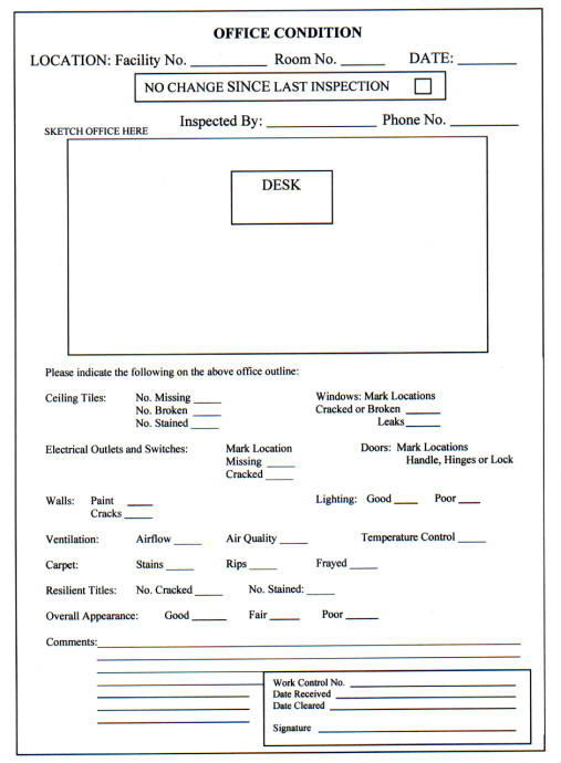 |
 |
10.5.2.6. Facility Condition Inspection. The Facility Condition Inspection is a part of the FCA process as discussed in paragraph 10.5, Continuous Inspections.
10.5.3. Inventory. The facilities and equipment inventory is the baseline for what is inspected and maintained. The inventory should permit identifying inspected items, items subject to PM inspection, and items subject to operator inspection. Chapter 3, Facilities Maintenance Management, discusses facilities and equipment inventories.
10.5.4. Frequency of Inspection
10.5.4.1. As the name implies, continuous inspections should be ongoing, with all facilities and equipment inspected periodically. The frequency of inspection depends on a number of factors, including the following:
a. Importance of the facility.
b. Legal or regulatory requirements.
c. Likelihood of condition changes since the last inspection.
d. Safety considerations.
e. Availability of inspection resources.
10.5.4.2. Table 10-1 provides suggested inspection intervals for a number of facilities and systems. These apply to facilities and equipment under average conditions supporting routine operations. Centers should adjust the frequencies to suit local conditions, regulatory requirements, known equipment conditions as a result of PM and PT&I, operational requirements, and user inputs.
10.5.5. Inspection Procedures. Preparing for and conducting an inspection involves many of the following steps, all of which may not apply in the case of PM Inspections and operator inspections:
a. Identifying the items to be inspected, based on the inventory.
b. Obtaining the facility or equipment history. This includes information on completed and pending work orders, as well as the results of past inspections and the current use of the facility or equipment.
c. Reviewing the applicable physical condition standards with a view toward the planned use of the facility or equipment. (Facilities or equipment scheduled for disposal or deactivation normally will have lower maintenance standards.)
d. Identifying planned changes to the configuration and use of the facility or equipment.
e. Identifying the inspector skills, specialized tools, and equipment required for the inspection.
f. Scheduling the inspection and setting the inspection route, considering the operational requirement for the facility, the availability of inspectors, and related factors. Factors such as safety certification requirements, mission criticality, observed rate of deterioration or condition change, and system availability determine inspection schedules and frequency.
|
g. Conducting the field inspection and documenting the conditions found. The documentation should be a clear and concise presentation of the conditions found and permit determining and estimating corrective action. (Serious and safety-related deficiencies should be entered into the work control system for immediate action.)
10.5.6. Inspection Followup. The following actions are normally taken with regard to deficiencies found during an inspection:
10.5.6.1. Reporting Conditions and Recommendations. Inspections are intended to be used for determining and initiating corrective action. Therefore, it is important that problems be reported and a recommended corrective action be submitted to cognizant facilities maintenance managers for decisions on corrective action. The following are a range of corrective actions:
a. Issuing work orders.
b. Expanding the types and increasing the frequencies of PT&I tests to allow for closer monitoring of the problem.
c. Including corrective action in the Annual Work Plan or 5-year Plan.
d. Preparing a facility project.
e. Modifying maintenance standards or actions.
f. Including the deficiency as part of the BMAR.
g. A combination of the above.
10.5.6.2. Estimating Corrective Actions. The cost estimate associated with an inspection report typically is a Scoping Estimate. However, repair work orders normally require a detailed estimate. All of the information obtained during the identifying and estimating process should be documented, including any impact on the customer. All information is then entered into the work control process for further determinations of prioritization, approval or deferral, and scheduling for accomplishment, as discussed in Chapter 5, Facilities Maintenance Execution.
10.6.1. NASA Centers are responsible for identifying and quantifying facility conditions in order to support annual and 5-year Work Plans. The FCA is the method by which the Centers meet this obligation. Traditional methods of FCA have proven costly and historically have diverted money from needed maintenance. However, adoption of the RCM philosophy, PT&I, CMMS, and proactive maintenance approaches provide Centers with information related to facility condition that was not previously available. These new information sources, coupled with increased customer and user input, have the potential to provide valuable FCA data without having to perform many of the discrete inspections required under the traditional FCA processes. Any facility and equipment deficiencies identified in the FCA will be evaluated for failure and failure consequences (risk assessment) to identify safety impacts. When the evaluation identifies a safety impact (hazard to personnel or NASA property) the Center's safety office must be notified and appropriate action must be taken to alleviate the hazard. In addition to safety deficiencies, appropriate followup action should be taken to correct any of the other deficiencies identified.
10.6.2. Headquarters also requires adequate FCA information to ensure its proper stewardship over facilities entrusted to NASA, as well as to assist the Agency senior management and higher authorities (Congress, OMB) in projecting facilities budgetary needs relative to NASA's mission.
10.6.3. A third use of the FCA process is as a tool to evaluate contractor performance under a Performance-based Contract. While the FCA cannot address all aspects of the contractor's performance, it can be used to prognose the direction the Center is headed. For example, an increase in the number of equipment units in a PT&I alarm condition and/or an increase in the normalized TC rate should be leading indicators of a degrading condition for specific facilities, systems and equipment.
10.6.4. NPD 8831.1 requires that Centers continuously assess facility conditions to identify and quantify their BMAR so as to be 80-percent accurate at any point in time. This includes electrical, mechanical, and utility systems, buildings, roads, and grounds. FCA's are inspections and evaluation of data to ascertain condition only and do not include such maintenance actions as adjustments, lubrication, or repair. Since a Center's facilities are in a constant state of change due to normal wear and tear, renewal tasks, and reconfiguration, the FCA process must be dynamic if an accurate estimate of a Center's condition is to be obtained.
10.6.5. Following the general philosophy of maintaining reliable performance at the least cost, the FCA process should be more heavily weighted towards system function and customer (Facility User), than on age and appearance. Further, the process should not be labor intensive and should be at the least cost. To meet these requirements, Centers should utilize all of the inspection techniques listed in paragraph 10.5, Continuous Inspection, as appropriate along with their CMMS databases. Maintaining strict database management and accuracy is essential if a real time FCA process is to exist. The assessment should determine the condition or operational status of each item of equipment or facility as compared to a predetermined facilities condition baseline. Appropriate followup action should be taken to correct any deficiencies identified to include them in the AWP and to update the Center's BMAR and ROI records and the 5-year Plan.
10.6.6. Facility Classification. A consistent facilities-type classification process should be used that allows like facilities to be compared to one another statistically and financially. All facilities shall be classified into one of the following:
a. Office.
b. Research and Development (R&D) Facility.
c. Computer (Special Purpose) Facility.
d. Hangar/Aircraft Support.
e. Production Facility.
f. Non-Buildings (Trailers, temporary structures, air- or tension-supported facilities).
g. Laboratories.
h. Central Utility/Power Plant Facilities.
i. Utility Distribution Systems.
j. Roads and Grounds.
k. Other Miscellaneous Facilities.
10.6.7. Facility Criticality. Facility and infrastructure criticality is defined in terms of safety, impact on the mission, impact on the Center, and other categories listed in Table 10-2. Single points of failure - equipment that when fails, causes the entire system to fail - should also be considered.
CRITICALITY |
CRITERIA |
|---|---|
| 1 | Environment, health, safety impact with a single point of failure. |
| 2 | Mission impact, single point of failure. |
| 3 | Environment, health, safety impact, multiple failures required. |
| 4 | Mission impact, multiple failures required. |
| 5 | Center impact (non-mission). |
| 6 | Significant economic consequences. |
| 7 | Employee morale. |
| 8 | Public relations. |
10.6.8. FCA Process Model. Figure 10-3 is a sample basic model for Center use in establishing a FCA program. CMMS data, statistical analysis, facility user, and Facility Manager input should be used in conjunction with the TC, PM, and PT&I databases.
10.6.9. FCA Analysis
10.6.9.1. Use of CMMS Data. The assessment should use CMMS data as an integrated part of its evaluation. The data can be analyzed statistically and searched for patterns or clusters that indicate changes in the condition of facilities and equipment. For maximum benefit to the FCA analysis, the CMMS should have data in the following fields:
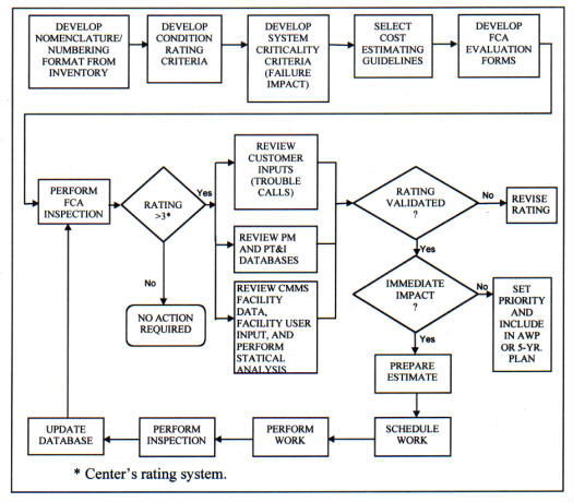 |
a. Condition Codes.
b. Failure Codes.
c. Cost Data (labor and material).
d. Facility Type.
e. System Criticality.
f. Functionality.
g. Age of the Equipment.
h. Parts Availability.
i. Repair History.
j. Serviceability.
k. Energy Efficiency.
10.6.9.2. Statistical Analysis of CMMS Data. The data should be normalized by, among other things, the type of facility, square footage and the number of occupants, and the normal and standard deviations determined and trended over time. The trend line ideally should have a negative slope, indicating an improved condition.
10.6.9.3. Analysis of Energy Management and Control System (EMCS) Data. EMCS data should be analyzed as part of the FCA process to determine energy efficiency/ consumption changes that may indicate a deteriorating equipment or system condition (Appendix B, resource 7) that requires O&M action.
Maintenance actions are the specific work tasks performed by the maintenance workers. These actions are the basis for work orders, workforce scheduling, and preparing budget estimates and work plans. Maintenance actions used in work orders are normally detailed, covering task specifics, while actions used for budgeting and long-range planning are more often generic or statistically derived.
10.8.1. Standards. Facilities design, colors, facades, and landscaping should fit in with other external architectural features, including signage, traffic flow, and visual and acoustic barriers. The resultant system should blend with local community standards and decor and properly represent NASA to the public. Where possible, the plan should emphasize low-maintenance features. Specific design guidelines are beyond the scope of this procedures guide. Facilities master plans often include landscaping plans, standards, and guidelines prepared by landscape architects. Landscape plans should include recommended maintenance actions. Facilities maintenance planning, including inspections and recurring maintenance, should ensure that facilities and grounds appearance represent NASA's best interests.
10.8.2. Grounds Care Guidelines. A large number of resources are available for obtaining guidelines for grounds care. These include Government publications, local agricultural extension services, trade and industry publications, and commercial grounds care services. Grounds maintenance plans should conform to the Center master plan and have the support and approval of senior Center managers. Grounds care frequently involves using controlled chemicals such as pesticides and herbicides, fertilizers, and other materials with potentially adverse environmental impacts. All work plans should include appropriate environmental and safety requirements.
10.8.2.1. Maintenance Levels
a. Based on land use, frequency of visitation, and visibility, Centers may wish to vary the quality (and cost) of grounds maintenance services specified for different parts of the Center. The following four levels are suggested:
(1) Level I - Administrative areas.
(2) Level II - Industrial, warehouse areas.
(3) Level III - Open storage, waterfront areas.
(4) Level IV - Railroad and power line rights-of-way.
b. Each maintenance level contains a distinctive mix of service requirements.
c. The service quality decreases as the maintenance level increases (e.g., grass cutting weekly in Level 1, every 2 weeks in Level II, monthly in Level III, and quarterly in Level IV (sufficient to reduce the fire hazard)).
10.8.2.2. Level of Service. There are three methods of specifying the level of Grounds care maintenance: frequencies, standards, and outcomes. Grounds care contract experience over many years at different locations has shown that specifying frequencies is preferable to specifying standards. Frequencies are easy to plan, schedule, enforce, and estimate costs. Grounds Care standards such as grass height or shrubbery appearance are difficult to estimate and enforce. Specifying outcomes, such as "lawns shall be green and well maintained at all times" is highly subjective and reliant on the contractor's proposed plan as part of the selection criteria, but is used with increasing frequency with outcome-based contracts.
10.8.2.3. Performance Requirements Summary. Grounds Care contracts should contain a performance requirements summary in simple tabular form. Table 10-3 is a sample of a performance requirements summary. Chapter 12, Contract Support, discusses grounds maintenance and other performance and outcome-type contracts in greater detail.
a. Gathering MSI is a process of collecting life-cycle maintenance information on facilities and equipment. Table 10-4 is a list of typical MSI; all items listed may not apply in all cases. This table provides a basis for an MSI checklist.
b. Historically, collecting, documenting, organizing, and maintaining facilities and collateral equipment MSI has been difficult. Modern CMMSs can be used to perform most of these functions automatically.
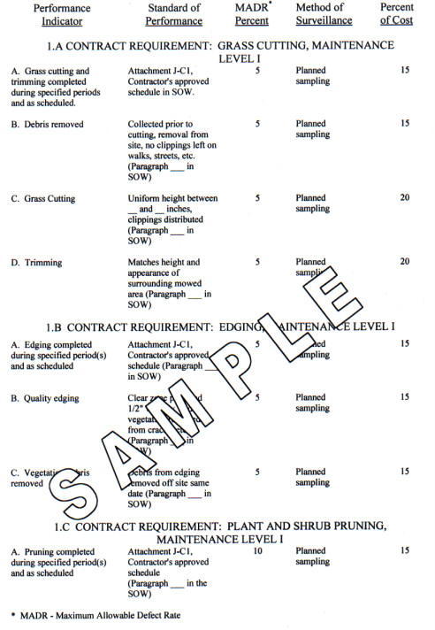 |
|
10.9.1. MSI Library
10.9.1.1. NASA facilities are aging, and there is a reduction in the frequency of replacement. Therefore, more attention must be given to maintaining existing facilities effectively and to collecting and recording MSI for those facilities. This requires a managed maintenance library system. Maintenance documentation becomes more valuable as facilities age. The library control procedures in the maintenance organization must ensure that MSI documents are identified, cataloged, and maintained so that they are available during the entire life-cycle of the facilities and equipment. All documents and records should be filed and retained in accordance with guidance provided in NPG 1441.1, Records Retention Schedules.
10.9.1.2. The MSI library can be dispersed if it is controlled and periodically inventoried. The library is most useful when it is readily available to the personnel who need the information and they can obtain it without undue effort. In the long term, this information should improve the effectiveness of the total maintenance operation. As MSI is incorporated into the CMMS, more of the maintenance personnel in the shop areas have access to the information, and necessary control is afforded by the CMMS itself.
10.9.1.3. MSI control is particularly important during the turnover of maintenance operations between contractors or from in-house to contractor operation. MSI that is considered unimportant during a transition period may become vital when an item of equipment starts to fail.
10.9.1.4. For new facilities and equipment, the vendor or construction contractor frequently provides MSI. However, it often is not in a form or in an amount sufficient to meet facilities maintenance needs. Further, manpower is not always available to develop facilities maintenance standards and procedures based on vendor- or contractor-provided information. Training provided by the contractor or vendor may or may not be adequate.
10.9.2. Policy
10.9.2.1. NPG 8820.2, Facility Project Implementation, makes provisions for obtaining MSI as part of the facilities project preparation and implementation process.
10.9.2.2. Paragraph 10.9.1, MSI Library, discusses the library and the need for having all existing MSI documents under library control. The following paragraphs address obtaining MSI for new facilities as part of the design process. Similar procedures can be used to obtain an A&E to gather information for existing facilities.
10.9.3. Planning
10.9.3.1. Identifying MSI should be an integral part of the planning process for new facilities. Its cost should be included in budget estimates for project design. MSI should be a deliverable prepared by the design A&E. MSI should be due when the facility is nearing completion, prior to beneficial occupancy. In this way, maintenance requirements should receive full consideration in the design process. This should result in a more easily maintained facility with full maintenance data and systems support at the time of occupancy.
10.9.3.2. Where the Center lacks adequate MSI for existing facilities, especially mission-critical facilities, use of an engineering services contract to gather MSI is recommended. This contract may be combined with a condition assessment or inventory contract or handled as a separate contract solely for MSI.
10.9.4. Procedures. While the management of A&E contracts may fall outside the responsibility of the facilities maintenance organization, the facilities maintenance organization should take an active role in developing MSI requirements. The following paragraphs describe a typical approach to the development of MSI and the organizations responsible for the necessary actions.
10.9.4.1. Center Responsibility. The Center is responsible for the following:
a. Determining whether a new or existing facility or equipment requires MSI and budgeting for the acquisition of MSI.
b. Including a requirement for MSI in an appropriate contract (i.e. in the A&E's design scope of work for a new facility as part of the scope of work for an engineering services contract for condition assessment or inventory or as the scope of work solely for MSI development. This includes determining the level of MSI detail, submission form, and formats required from the contractor.
10.9.4.2. Joint Center and Contractor Responsibility. The Center and the contractor should work together to identify items that require MSI.
10.9.4.3. Contractor Responsibility
a. The A&E contractor may be tasked to provide any or all of the following items:
(1) For new facilities or collateral equipment, specifying the MSI required from the construction, equipment installation, supply contractor, or equipment vendor.
(2) For existing facilities or collateral equipment, obtaining the information directly from the manufacturers or vendors of the existing facilities and equipment.
(3) Integrating the contractor-furnished information with the facility design features, and using the facility data (including Center operational requirements) to update the facility and equipment inventory and to document appropriate maintenance standards and procedures.
(4) Assembling the MSI into the required deliverable formats.
b. If any of these items are required, the requirements documents (and resultant contract) must reflect the project needs and deliverables accordingly.
10.9.5. Deliverables. The deliverables required by the MSI specifications may take several forms. In the past, hard copies of manuals, drawings, and maintenance procedures have been the most common. However, other formats are possible. Where automated inventory and maintenance management systems are in use, the MSI acquisition should include uploading the MSI into the CMMS. Deliverables should be in computer-readable formats, including Computer-Aided Design and Drafting (CADD), and GIS drawings. MSI specifications should call for linkages between drawings, drawing components, and CMMS databases where appropriate.
This chapter provides guidance for utilities planning and management and describes the concepts and philosophy for the Operations and Maintenance (O&M) of central utility plants, such as central heating or steam plants, central air conditioning (chiller) plants, air compressor plant, and water and wastewater treatment plants. These central utility plants are normally operated and maintained by a Center's facilities maintenance organization.
11.2.1. Purpose.
11.2.1.1. Comprehensive planning and management of utilities is essential for securing adequate and cost effective supplies of current and expected needs of electricity, natural gas, steam, water, and wastewater for NASA. The intent is to secure the most reliable utility services at the lowest cost consistent with NASA's mission, environmental standards, and waste reduction. The utilities are required to support various energy-consuming systems at NASA facilities. Some of the primary energy-consuming systems commonly found at NASA facilities include the following:
a. Heating and power plants.
b. Steam distribution systems.
c. Hot-water and chilled-water distribution systems.
d. Electrical distribution systems.
e. Compressed-air distribution systems.
11.2.1.2. While existing utility requirements are satisfied, future growth, as well as emergency situations, should be anticipated and properly planned. Factors to consider are the future needs of the utilities and system capabilities, potential threats to existing services, alternative solutions to ensure adequate future supply, and finding and developing new sources of the energy products. Where necessary, utility systems upgrades should be implemented where new sources have not been identified. Utility planning and management instituted to promote system efficiency should also include emergency preparedness.
11.2.1.3. At the Center level, utilities management has the following major functions:
a. System Development - directed toward the design or planned improvement of generation, distribution, and collection facilities to achieve efficient and economical system operation. Inherent in system development is the evaluation of alternatives such as the types of energy to be used, centralized versus decentralized systems, and the means to acquire utility services.
b. Operations and Distribution - directed toward maximizing the efficiency of production, distribution, and collection equipment using minimum manpower and materials.
c. Inspection and Maintenance - directed toward minimizing system downtime at minimum cost.
d. Usage Control - directed toward minimizing waste.
11.2.1.4. In addition to assuring adequate, reliable, and cost-effective utility services, proper utilities planning and management requires the attentiveness of externalities such as privatization initiatives, electric utility deregulation, utility purchasing options, and the future of demand-side management.
11.2.2. Privatization
11.2.2.1. The privatization of utility functions is the transfer of in-house operations to private entities. Privatization can be executed by outsourcing or by asset sale. Outsourcing is contracting services through a competitive bidding process, while maintaining financial, management and policy control over the services. Asset sale is the transfer of ownership to the private sector, where the Government has no role in the oversight of the sold assets (see Appendix B, resource 31). The goal of privatization is to achieve savings resulting from the introduction of new technologies, increased worker productivity, and improved operating efficiencies. The following factors will greatly reduce the risk in privatization:
a. Clear need and demand for service.
b. Visible total cost of in-house service.
c. Capability to provide oversight of and monitor the effectiveness of contractors.
d. Local control of decision to privatize.
e. Clearly defined goods and services.
f. Ability to define acceptable quality in measurable terms.
g. Flexibility to balance cost and quality.
h. Competitive markets.
11.2.2.2. The focus of many privatization efforts is to achieve a high level of reliability while optimizing in-house resources. In-house expertise must be maintained in order to facilitate contractor relations. Careful communication and planning with personnel are imperative when it comes to alleviating the perceived threat of contracted services. The best available in-house skills are needed to establish contractor accountability and review performance evaluations. The benefit of privatization is that the burden of daily operations are transferred to the contractor who has greater flexibility to hire the necessary expertise and implement technology on an as-needed basis, thereby optimizing resources.
11.2.3. Fuel Source Planning
11.2.3.1. Concomitant with the goal to minimize petroleum usage promulgated by Executive Order 12759, Federal agencies were required to survey their buildings and facilities to determine where the potential for dual-fuel capability exists and to provide such a capability where practicable. Dual-fuel capability is any technology that provides the ability to switch from one fuel source to another for generating energy, thus reducing dependence on any one source of supply. A facility with dual capability can switch relatively easily and quickly to a second fuel if the first fuel is either unavailable or more expensive per delivered BTU than the second fuel. Field Installations are responsible for pursuing alternative energy sources and identifying candidate projects. For many NASA Installations, the most feasible of these is natural gas conversion, but other possibilities exist as diverse as refuse-fired steam plants or geothermal heat. The benefits of such initiatives include a reduced susceptibility to petroleum market forces, less pollutant emissions, and possible reduction in facility maintenance requirements. Expansion of natural gas usage could allow replacement of high-energy-consuming electrical equipment and appliances with gas-fired units.
11.2.3.2. The main practical application of dual-fuel capability is to support the purchase of natural gas on the "spot" market - an alternative contracting mechanism for purchasing natural gas. The spot market refers to the purchase of gas from the producer rather than the local gas utility. The end user can make spot purchases either directly from the producer or indirectly via a gas marketer. Spot market transactions are usually short-term, "interruptible" purchases. Interruptible deliveries can be interrupted by any one of a number of contingencies: unusually cold weather, producer shutdowns, and a temporary lack of pipeline capacity.
11.2.3.3. Short-term interruptible contracts make supplies less certain. In addition, while spot market gas is normally cheaper than gas purchased under long-term contracts, prices can increase more quickly. Both possibilities make dual-fuel capability almost essential when purchasing spot gas. When natural gas is unavailable or undergoes a rapid escalation in price, a facility can switch dual-fuel boilers relatively quickly to burn fuel oil instead. Such a facility can then switch back to natural gas when it becomes available and affordable. Some local distributors will reduce the price of their natural gas if the Field Installation agrees to switch to an alternative fuel during a time when capacity has been curtailed. Such an arrangement can result in savings for both the local distribution company and the Field Installation.
11.2.3.4. The spot market for natural gas expanded dramatically when the Natural Gas Policy Act (NGPA) of 1978 deregulated the market. All Field Installations with the potential for participation in wholesale natural gas contracting may participate in the central procurement program offered by the Defense Logistics Agency (DLA). Field Installations interested in taking advantage of the potential cost savings available in the spot market for natural gas should contact the Defense Energy Support Center (DESC) for information about their Competitive Direct Supply Natural Gas Program. The General Services Administration (GSA) National Center for Utilities Management also provides contracting support to federal agencies.
11.2.4. Electric Utility Deregulation National Status
11.2.4.1. Electricity competition in the United States is continuing to reshape the electric utility business. Historically, electric utilities have been vertically integrated utilities regulated by State Public Service Commissions (PSC), which are also known as Public Utility Commissions (PUC). The commissions have allowed the utilities to operate as natural monopolies within defined geographic boundaries. The typical electric customer purchased power in a packaged deal-electricity production, transmission, and distribution, and metering, billing, and special services. The transmission and distribution services will continue under the regulatory guidelines set forth by the PUC.
11.2.4.2. The functional operations of a utility will not change. However, the power generation, and energy services will be contracted in a nonregulated environment that fosters competition. The federal Government has shared the responsibility of implementation to the states since each State has different operational concerns in electric service. In some States, the power of authority to implement retail competition, be it the State legislature or the PUC, has not been clearly defined.
11.2.5. NASA Host State Electric Utility Deregulation Update. Various aspects of electric utility economics functions are being scrutinized by individual States as the nation transitions into a competitive electric power market. States that have been the most aggressive in passing laws and implementing open access transmission on the retail level are those States where the average cost of electricity is 20- to 60-percent above the national average. Contact information regarding the electric utility deregulation status for each NASA host State can be found in Appendix B.
11.2.6. Utility Purchasing Options. Many different utility purchasing options exist. However, the purchase process has become more complex due to utility deregulation. Being aware of energy utilization enables the understanding of rate applicability and appropriateness.
11.2.6.1. Rate Structures
a. Utility providers design rate structures that capture the cost of production and delivery of the commodity. The components of the rate structure vary depending on the volume, time of use, and customer size. The price mechanisms used to set rate structures include the cost for capital investment, service delivery, operating expenses, pollution control, and environmental and social externalities.
b. Rate structures imposed usually reflect consumption patterns and users. Most electric utilities offer one of the four following models:
(1) General Rate structures are geared toward users with low consumption volume that is variable and difficult to forecast.
(2) Stable Volume Rate structures are for users with predictable loads and minimum time-of-use or seasonal variation.
(3) Interruptible Rates are for users with alternative power supplies. At the request of the utility supplier, service may be interrupted or curtailed for a limited period during the supplier's peak. The user can receive credit for helping to relieve the supplier's burden of peak supply.
(4) Modular Rates are for users with consumption that is difficult to forecast. Typically, consumption is sufficiently high to qualify for these rates.
c. Within the rate structures mentioned, price components may vary depending on mechanisms imposed or negotiated. Bill components may include the basic customer service charge, energy use charge, energy demand charge, taxes, and environmental compliance recovery. Large users can take advantage of other pricing mechanisms that may yield alternative cost saving opportunities, such as Real-time Pricing (RTP), voltage service discounts, and riders.
d. RTP is the hourly energy pricing usually purchased a day in advance. Typically, rates are higher during peak use periods. With RTP, facility managers can plan to implement energy use strategies to reduce consumption during high price periods. Depending on the energy supplier, RTP can be applied to usage that exceeds baseload definitions. The baseline capacity is purchased at standard rates. The RTP rates are supplied to the customer a day in advance. If the next day's usage exceeds the baseline, then the RTP rates are charged. For usage below the baseline, the customer receives a credit at the RTP rates per unit of the commodity.
e. Electric utilities offer discounts to customers who take advantage of high voltage service. The utility feeds the high voltage service directly to customer owned distribution equipment such as transformers, switchgear, and safety equipment.
f. Riders are associated with the use of new technology and participation in pilot programs or experimental services. Riders may be special charges or discounts applied to existing rate schedules. The rider type and amount will vary with the utility provider.
11.2.6.2. Load Aggregation
a. Load aggregation is the grouping of facilities with similar energy requirements and energy use patterns for the purpose of creating a conglomerate to increase purchasing power, thereby, reducing the energy costs.
b. Load aggregation is the central collection of energy use data from geographically dispersed sites. With the proper instrumentation, energy load data can be gathered to explore the best available rate options for a defined group of uses at multiple service accounts or facilities. If the user profiles are similar, the composite information can result in an attractive energy use profile and load factor. The attractiveness comes in the consistency and predictability of energy use patterns which reduces the power producer's risk in generating electricity, thereby reducing the price. With load aggregation, measuring when and how energy supplies are used enables the aggregators to negotiate the best price for energy contracts.
c. Differences in climates, occupants, and building construction are further issues of concern when considering the potential for load aggregation.
d. Load aggregation enables the end-users to develop competitive leverage against host utilities.
11.2.6.3. Unbundled Services. Transmission and distribution services will still be regulated to ensure accessibility, safety, and reliability. Transmission entities will be regulated by the Federal Energy Regulatory Commission and will provide service via the power exchange or Independent System Operator. The distribution entity will remain as we know it: the wires will still be used to supply electricity in compliance with State regulations. Generation companies, the owners of power plants, will sell power to power pools and distribution companies. They will also have opportunities to contract with the power exchange, the Independent System Operator, and with retail customers. Competitive energy services, dubbed as retail services, will introduce a broad range of energy-efficiency programs and services in a deregulated environment. The energy retailer will have opportunities to market customers, procure power for customers, and provide account management services.
11.2.6.4. Competitive Bidding. Competitive bidding is the process of comparing bids solicited from individual contractors. All bids should be evaluated under the same guidelines. The contract award usually goes to the bidder offering the "best value" solution.
11.2.6.5. Existing Utility Service Providers. Local utility providers will still play an important role in future electricity procurement. They will still provide transmission and distribution services for NASA Centers. The purchasing options are:
a. Continue all services with the local utility company,
b. Select a hybrid arrangement with the utility supplying base loads and an alternative provider supplying critical or excessive loads, or
c. Select alternative providers for generation and energy services.
11.2.6.6. Federal Support for Power Procurement
a. Two Government entities, the DESC and GSA, offer varying degrees of electricity procurement support. The DESC's mission is to provide the Department of Defense and other Government agencies with comprehensive energy support in the most effective and economical manner possible.1
b. GSA's Public Utilities Division is also providing electricity procurement services for Federal agencies. GSA has organized a Center of Expertise to facilitate activities relative to energy conservation and management, deregulation and utilities, and other public utilities interests. Each GSA region will assist facilities with price negotiations and contracting services. Appendix B contains the list of regions along with the geographic areas of coverage, regional energy coordinators, and model area wide contract.
11.2.6.7. Alternative Utility Service Providers
a. The competitive power market will involve a variety of agents to coordinate electricity transactions: utility companies, power producers, Independent System Operator, and power marketers.
b. Utility companies will be the basic electric service providers with an obligation to serve incumbents and those who leave and return. Utilities will be regulated with the mandate to provide universal service, ensure social and environmental responsibility, and construct and maintain all distribution lines. The only changes in the core business of the utility and transmission service will be the price and terms of electricity service, since the utility will be the reseller of electricity from the market.
c. Non-utility power producers will engage in a competitive bidding process to serve electricity. The end user will be responsible for arranging delivery services. The diversity of power producers increases the opportunity to coordinate generating operations and maintenance. However, strict scheduling will be needed to ensure the delivery of safe and reliable power.
d. The Independent System Operator will be commissioned to maintain network efficiency and reliability on the generation and transmission system. The Independent System Operator will also be charged with monitoring fair and open access to the transmission system. Controlled service areas will be or have been established in order for the Independent System Operator to maintain a balance of supply resources with user demands and dispatch generators accordingly.
1Worldwide service for DESC customers and suppliers is available by calling 1 (800) 286-7633, or you can obtain more information by visiting the DESC website at http://www.desc.dla.mil.
e. Power marketers typically serve as intermediaries between buyers and sellers, reduce prices, and offer value-added services. As commodity brokers, power marketers will compete with each other to find and deliver the most economical and reliable power available to the customers.
11.2.6.8. Utility Energy-efficiency Service Contacts. An additional contracting mechanism that is available to Federal agencies is to work directly with an electric utility to implement the project. The Environmental Protection Agency (EPA) is the primary Federal agency that authorizes and encourages Federal agencies to work with their local utility to implement energy saving projects. Refer to NPG 8570.1, Energy Efficiency and Water Conservation Technologies and Practices for procedures on using this alternate financing mechanism.
11.2.7. Data Management
11.2.7.1. Data management is the collective practice of maintaining records of all utility billing and services. Since reporting energy use information is required by Executive Order 12902, data management can have multiple benefits for management personnel.
11.2.7.2. Metering of all utilities, including process-related services, provides sufficient data to review billing transactions, usage patterns and levels, and system efficiencies. Data management packages the metered information in a manner that provides visual identification of problems and opportunities. Performance problems can be quickly identified followed by immediate corrective action. Opportunities for energy efficiency projects can be evaluated and justified with factual data. This knowledge base helps energy managers and facility management personnel with proper resource allocation.
11.2.7.3. Some utilities are currently offering group billing to consolidate accounts for those customers with multiple facility metering. Electronic files are available upon the customer's request. These services reduce the burden on energy accounting and reporting functions. Data management provides the following:
a. Streamlined billing process-reduces accounts payable encumbrance and simplifies data entry
b. Utility bill validation-identifies incorrect billing factors and provides usage versus weather statistics
c. Energy analysis-identifies building or system inefficiencies, tenant usage patterns, and billed versus actual demand
d. Rate schedule appropriateness-verifies account ownership and ensures best available rates for service, late fees, taxes, and surcharges
e. Retrofit evaluation-evaluate energy retrofit cost avoidance and determine effectiveness of energy management programs
f. Budget preparation-provides data for preparing cost and usage trending reports
11.3.1. Objectives. The following are objectives for the O&M of central utility plants:
a. Providing central utility services without waste to support Center needs including mission and test requirements.
b. Operating the plants efficiently and economically.
11.3.2. Plant Operations and Maintenance Considerations. The concept for the O&M of a central utility plant is that operators are assigned full time to operate the plant, but they perform maintenance between various operating tasks. Operator maintenance as it is often referred to, involves a significant integration of facilities and equipment inspection and maintenance with routine watch-standing operations.
11.3.2.1. Staffing. Central utility plant operations and maintenance normally require a nearly constant level of effort varying only with seasonal changes. Operators as a minimum must meet license, permit, and certification requirements per paragraph 3.6.2.3, Licenses, Permits, and Certifications. In addition to these requirements plant operators must be thoroughly familiar with the assigned plant and its operating, maintenance, and safety requirements.
11.3.2.2. Maintenance Actions. Condition-monitoring (PT&I) and PM actions are frequently a part of the operating procedures for central utility plants and are performed by the operators as part of their routine watch-standing duties. Additionally, plant operators may be directly involved with the repairs, Replacement of Obsolete Items, and Programmed Maintenance on those portions of the plant they operate. Maintenance action development should use the techniques discussed in Chapter 7, Reliability Centered Maintenance.
11.3.2.3. Standards. Central utility plants are usually process oriented, providing a product or service, with emphasis on availability and reliability. Standards developed for Central Utility Plant Operations and Maintenance must have this focus. These standards should identify conditions that require nonoperator assistance as well as conditions addressed by the operators. The methods for setting standards discussed in paragraph 10.3, Facilities Condition Standards, are applicable and should be utilized.
11.3.2.4. Operator Maintenance (Inspections). Operator maintenance is the examination, lubrication, minor repair (usually no larger in scope than TC), and adjustment of equipment and systems in the assigned plant. This maintenance and the inspections are directed toward minimizing system downtime at minimum cost. Operators should provide condition assessments for documentation in the CMMS as a part of the continuous inspection program.
11.3.2.5. Standard Operating Procedures. Standard operating procedures should be developed to cover routine operations, start-up and shutdown, operator maintenance, PM, PT&I, and emergency actions such as load-shedding plans, emergency customer notification, and local utility company coordination. Contingency plans should be developed and kept current.
11.3.2.6. Inspection and Certification. All central utility plant boilers and unfired pressure vessels must be inspected and certified in accordance with NPD 8710.5, NASA Safety Policy for Pressure Vessels and Pressurized Systems.
11.3.3. Heat Plant Operations. The operation of a central heating plant includes the start-up and shutdown of heating equipment and operator maintenance and inspection. Operations include the efficient and economical production of steam or high temperature hot water to assure its availability to the Center at the lowest possible cost. This work also includes record keeping of operations and conditions and the analysis of records to correct nonoptimal practices. It includes water treatment, monitoring warranties, testing operations and capabilities of the central heating plant, periodic operation and inspection of idle equipment, and cleaning, preservation, lubrication, and adjustment of plant equipment. Heat plant operations require control of the following functions:
11.3.3.1. Equipment Scheduling. Equipment scheduling requires matching heat generation with heat load requirements. This requires knowledge of demand curves, unit cost curves (with selection of single-boiler operation or multi-boiler operation), banking and startup costs, loading factors, and monitoring of both equipment selection and scheduling.
11.3.3.2. Equipment Operation. Equipment should be operated to achieve operating efficiency at operating loads. To accomplish this, boiler performance should be analyzed based on actual operational data taken from logbooks and used to identify changes required to achieve optimum efficiency in steam/hot water production. Hourly log entries should include weather data; stack temperature; feed water data; steam/hot water quantities, pressures, and temperatures; and carbon dioxide and oxygen readings. The optimum thermal efficiency curve for each unit should be obtained from the boiler manufacturer and used in operating the boilers.
11.3.3.3. Water Testing and Treatment. At each shift turnover each day that a plant is in operation the operators should collect feedwater, boiler water, and condensate samples from each operating boiler for testing. Tests results should be maintained within Center established limits for phosphate, sulfite, pH: range, hardness, causticity (alkalinity as OH), and total dissolved solids. Test results should be recorded with plant reports and logs.
11.3.3.4. Plant Reports and Logs. The operators should maintain operating logs on all operating equipment that will note operator checks and adjustments, and a record file noting normal or abnormal operating conditions, deficiencies or malfunctions, and corrective action taken. All recording charts and logs should be filed chronologically and kept in accordance with Center policy.
11.3.4. Central Air Conditioning (Chiller) and Air Compressor Plants. Plant operations should be conducted in accordance with applicable manufacturer's recommendations (such as manuals, specifications, brochures, literature, directives, and pamphlets), and Center established policies including, but not limited to, safety, energy conservation, and specific mission requirements. A part of operations should be the performance of any needed minor adjustments and repairs (see paragraph 11.3.2, Plant Operations and Maintenance Considerations).
11.3.4.1. Cooling Tower Systems. The O&M of cooling tower systems should include the performance of any needed minor adjustments and repairs to structures and components, monitoring and treating circulating water to prevent accumulation by precipitation of scale, corrosion, biological growths, and other foreign materials. Also included should be the flushing and cleaning of cooling tower pans (sumps) and disposal of sludge from the pans. Sludge disposal must be in accordance with environmental rules and regulations since sludge is considered hazardous waste.
11.3.4.2. Chemical Treatment of Closed Loop Distribution Systems. Centers should establish and maintain a chemical treatment program for the central cooling plant distribution system. Inspection checks and subsequent adjustments should be made to chemicals at least every 90 days to maintain pH limits of 7.0 to 10.0, and nitrite levels of 500 to 1,000 ppm as N02. Detailed records of the results of all inspection checks and chemical treatments should be maintained.
11.3.4.3. Plant Reports and Logs. Equipment deficiencies beyond the scope of operator maintenance should be noted on operational log sheets or recorded in the CMMS. Log sheets should be filled out as part of each operational check. Cooling tower and closed loop distribution system data should be recorded in the CMMS for future contracting purposes (see Chapter 12, Contract Support).
11.3.5. Water Treatment Plants. These plants include water pumping and treatment equipment and storage tanks. The plants should be operated and maintained as recommended by the equipment manufactures and in accordance with Center and local, State, and Federal laws, rules and regulations. A certified water treatment plant operator should operate the plant. The potable water should be free of taste and/or odor and meet water quality standards.
11.3.6. Wastewater Treatment Plants. Centers are responsible for compliance with all requirements of their National Pollutant Discharge Elimination System (NPDES) permits, as imposed by the Environmental Protection Agency (and/or as imposed by the State or local government). Properly qualified personnel, with required State certification shall operate the wastewater treatment facilities. All certifications must be maintained up to date and valid at all times.
11.3.6.1. General Waste Treatment Operations. Wastewater treatment facility operations should provide continuous, cost effective, and efficient treatment of all wastewater delivered to the facility. Such operations should include general operation of plant equipment, valves and piping, sampling and lab analyses, waste and effluent disposal, and other related services. Treatment facility conditions must meet applicable health and safety standards and be maintained clean and orderly at all times. Operations shall be accomplished with proper regard to equipment and components to ensure operating efficiency and longevity of service life.
11.3.6.2. Waste Disposal. Waste must be disposed of at a frequency sufficient to maintain clean and orderly collection sites with no overflow of waste material. Wastes (including sludge, grit, screenings, and other waste solids) must be routinely collected and transported to a properly classified disposal site. Wastes deemed hazardous must be transported and disposed of in accordance with Department of Transportation (DOT) and EPA requirements. All waste disposal practices must be accomplished in accordance with all applicable environmental regulations. All records, receipts, manifests, and log entries must be maintained in accordance with NPDES permit and State and/or local requirements.
11.3.6.3. Sampling and Laboratory Analysis. Sampling and laboratory analytical services must be provided to support regulatory agency operating requirements. Such sampling and testing procedures must be accomplished in accordance with applicable operating permit conditions. A complete set of laboratory records must be kept for all laboratory tests to include: date and time of sampling, type of sample, name of sample, sampling location, test performed, and test results. In addition, results of such laboratory analyses must be assembled into reports to conform to the procedures and requirements of the NPDES permit (or other State and local permits if applicable) and submitted to the EPA (or State and local agency). Copies of all testing records and associated correspondence must be maintained on file.
12.1.1. Historically, NASA has contracted for support of its maintenance activities. Typically, contracts would specify a level of effort to be provided rather than specifying the results to be achieved. However, the following are some of the problems associated with that approach:
a. It provides no incentive for contractors to be innovative or efficient.
b. It is uneconomical for the Government because it hires a "marching army" of contractor employees for a term of employment, instead of contracting for a job to be completed.
c. It may foster a personal services environment wherein NASA is perceived as the "employer" who supervises the efforts of contractor "employees."
d. It can contribute to a breakdown of project discipline (e.g., when the Project Office becomes concerned with how to keep the contractor busy, unplanned and often unnecessary "extras" may be added to the contractor's tasking).
e. It creates the opportunity for unnecessary enrichment of the labor skill mix, thereby driving up labor costs.
f. It requires the Government to perform extensive surveillance because, absent clearly stated contract objectives, the contractor must receive continual clarification from Government technical representatives.
12.1.2. NASA's policy is to "Utilize performance-based contracts and best-value principles to the maximum extent feasible and practical to shift cost risk to contractors and maximize competitive pricing". It is also NASA policy to include risk management as an essential element of the entire procurement process, including contract surveillance. In following these policies NASA has committed to converting its method of procuring facilities maintenance services from a cost reimbursement approach to a fixed price, performance-based contracting approach.
12.1.3. Refer to the NASA GPWS (Guide Performance Work Statement) for Center Operations Support Services (COSS) dated March 1997 and its Addendum dated July 1999 for complete background information, guidance, and templates that may be used by the Centers for their own customized PWS and Quality Assurance Guidance that proactively considers the elements of risk management. See Paragraph 12.6, Quality Assurance.
12.2.1. Under the PBC concept, the Government contracts for specific services and outcomes, not resources. Contractor flexibility is increased, Government oversight is decreased, and attention is devoted to managing performance and results and ultimate outcomes.
a. The Statement of Work (SOW) contains explicit, measurable performance requirements (WHAT), eliminates process-oriented requirements (HOW), and includes only minimally essential reporting requirements that are based on risk. The Government employs a measurement method (e.g., project surveillance plan) that is clearly communicated to the contractor, and where the contractor is held fully accountable. Incentives can be used, but must be relevant to performance and center on the areas of value to NASA and those of high risk that are within the control of the contractor. The SOW should encourage the use of contractor best practices and also include the requirement for the contractor to use cutting edge maintenance practices utilized in the private sector to give NASA the best product.
b. It is NASA's policy to maximize the use of firm-fixed-price contracts, combined with Indefinite-Delivery/Indefinite-Quantity (IDIQ) unit price provisions where necessary. In implementing this policy, as much "core" work as possible should be included in the firm-fixed-price portion of the contract. IDIQ work should be held to a minimum because of its cost.
(i) Fixed-Price Work. To shift cost risk to the contractor, fixed pricing and fixed unit pricing are used to the maximum extent feasible and practical. Because the contract requirements (time, location, frequency, and quantity) are known or adequate historical data is available to allow a reasonable estimate to be made, the contractor can agree to perform for a total price - similar to a single work order. The contractor does not get paid for work that is unsatisfactorily performed or not performed at all, and deductions are made in accordance with the Schedule of Deductions (Section E of the contract).
(ii) IDIQ Unit Price Work. Not every item of work can be adequately quantified at contract inception to allow it to be firm, fixed price. For example, few can predict the frequency and quantity of environmental spill cleanup actions that may be required over a given year, or the exact number of chairs and other preparations required for VIP visits and special occasions 2 years away. Often, too, historical data is inadequate to enable fix pricing certain services. Indefinite quantity contract requirements are performed on an "as ordered" basis. A fixed unit price to perform one occurrence or a given quantity of each type of work is bid for the requirement implementation. Payment is based on the unit price bid per unit (Section B of the contract) times the number of units performed or on an agreed-to price. Because each instance of IDIQ work is ordered and paid for separately, each and every delivery order must be inspected and accepted as being satisfactorily completed before payment is made, as if each were a separate mini-contract. Contract prices for unit priced tasks include all labor, materials, and equipment for performing that specific work. The unit prices offered are multiplied by the quantity of units estimated to be ordered during the contract term, but only for purposes of proposal evaluation, for work will only be paid for as ordered and completed.
c. The contract should be a completion type (something is accomplished) as opposed to a term/level-of-effort type of contract (effort is expended). I level of effort, staffing levels, or a skill mix of workers are specified, the contract is NOT performance based.
d. Contractor-Government partnering is highly recommended to achieve mutually supportive goals (see Paragraph 12.4, Partnering).
e. The Center Procurement Office should be contacted for assistance. The contracting officer will determine the appropriate contract type.
12.2.2. Facility Organization's Responsibilities. The Center facilities organization must work together with the users and it is recommended that the facilities organization participate in the preparation of the shaded sections shown in Figure 12-1 as a minimum and in the unshaded sections at the discretion of the Contracting Officer. This includes identifying all functions and services to be included in the contract; developing the functional tree diagram (which shows the relationships of the functions in the contract); and preparing a Work Breakdown Structure (WBS) for the technical section (Section C) and the PRS which is precisely coordinated with the tree diagram. The maintenance organization must assure the contract states that maintenance data entered in a CMMS is Government property and, as such, must be available for Government use and retention for historical purposes, regardless of who, Government or contractor, is responsible for populating and maintaining the database. Where the contractor operates the CMMS it must be made clear in the contract that the CMMS maintenance data is Government property and must be turned over to the Government at the end of the contract. The WBS must include all contract requirements to be purchased.
12.2.3. Functional Diagram. Figure 12-2 is an example of a functional diagram at one NASA Center. It represents graphically the highest level of the WBS and should be the starting point in preparing the PBC documentation. Recognize that it identifies graphically each function that is included in the performance-based contract. Each of these will be individually addressed and have a counterpart subsection in Section C where the requirements, performance indicators and other supplemental information is discussed. In this specific example, each shaded box represents a function discussed in the technical sections of the contract - Subsections C.8 through C.27. The large hashed-shaded area indicates that the five functions within it include operations support as well as maintenance. The white box functions are not in the contract, but are shown to indicate relationships. Functional diagrams will vary by Center, depending on the functions being contracted. However, its preparation and use is important and is the basis of the WBS and the contract documentation.
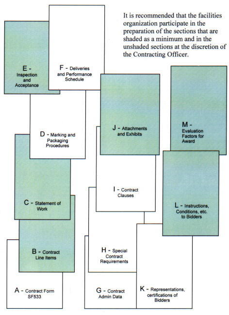 |
|
Performance-based specifications can be stated in terms of outputs or outcomes. For example, a typical performance-based contract will have numerous output requirements for maintaining facilities, such as performing PM, testing and treating circulating water in HVAC cooling towers and performing certain operational checks. An outcome requirement, however, simply might be that "buildings are available and fully functional to the user when needed," and integrates all service necessary to produce that result. Contractor flexibility is increased by allowing the contractor to decide what work tasks are needed and to propose cutting-edge technologies and techniques that may be more effective than traditional approaches. Government oversight is decreased and attention is devoted to managing final results. A certain amount of risk is introduced for NASA by transferring additional responsibility to the contractor and therefore is not appropriate for all functions. The use of output (versus outcome) requirements is suggested in the following circumstances:
a. The Center feels that the criticality of the function is too important to allow a contractor to deviate from proven work methods.
b. There is a mandated regulation or operational procedure that requires a specific work method to be followed.
c. A mandated procedural requirement is mandatory for safety considerations.
d. The function has very high visibility and a proven methodology has provided excellent results in the past.
12.3.1. Use of Metrics. Performance specifications require the identification of a standard of performance for the contractor's work. For example, an appropriate outcome specification may require the contractor to achieve a certain equipment availability. That is an outcome requirement. The metric or indicator associated with that requirement is percent (%) availability. The percentage number that the contractor must achieve is the standard (benchmark), set by the Center based on the current baseline performance that is acceptable to and being achieved by contractor or civil service forces at the Center. Unless these metrics are known, there is no rational basis for which to require a standard, and the use of the outcome specification may not be justified.
12.3.2. Reference. Refer to the NASA Guide Performance Work Statement for Center Operations Service Support Addendum (July 1999) for additional, detailed information on outcome specifications.
Partnering describes how well the customer and the contractor work together - that is, how well they communicate, how they resolve disputes, and how they execute the contract to fulfill each other's needs. It is a commitment by both parties to cooperate, to be fair, and to understand each other's expectations and values. It is an agreement between NASA and the contractor to work cooperatively as a team, to identify and resolve problems and to achieve mutually beneficial performance and result goals.
12.4.1. Partnering is a relationship between organizations where the following occurs:
a. All parties seek win-win solutions to problems rather than solutions that favor one side.
b. Value is placed on the relationship. There is an interdependence where if one party succeeds, all parties will benefit.
c. Trust and openness are a normal part of the relationship. The sharing of ideas and problems without fear of reprisal or exploitation promotes the fair and rapid solution to problems.
d. An environment of cost savings and profitability exists.
e. All understand that no one benefits from the exploitation of the other party.
f. Innovation is encouraged.
g. Each party is aware of the needs and concerns of the other. No actions are taken without first considering the effect they have on each other.
h. Each individual has unique talents and values that add value to the group.
i. Overall performance is improved. Gains for one party helps the whole group and are not at the expense of another.
12.4.2. NASA Centers should seek to partner with their support contractors. Benefits that are usually achieved by participating organizations include improvements in contractor-customer relationships, a reduction in claims, a reduction in time growth, a reduction in cost growth, and fair and mutual interpretations of the specifications.
In contracting for support it is assumed that the contractor will perform as specified in the contract. Experience has shown that contractors can meet contract requirements with performance ranging from a minimum of acceptable to a top performance of excellent. Incentives in Government service contracts are generally more negative than positive, with emphasis on invoice deductions for poor or nonperformed work. Rather than just deductions, incentives can be used to encourage the contractor to expend effort and resources and employ cutting edge breakthrough maintenance practices as used in industry to attain top performance. Following are examples of incentives that could be used.
12.5.1. Incentive Fee. An incentive fee provision can be included in a contract to encourage the contractor, through a suitable monetary incentive, to provide the management, equipment, materials, labor, and supervision necessary for performance improvement. Most often when positive fee type incentives are used the fee starts at 100- percent and then is reduced for subjective opinions of areas of dissatisfaction. A better incentive is the reverse that is starting at 0 and increasing for areas or instances of greater objectively measurable performance.
2.5.2. Award Term. The Award-Term is an innovative incentive approach, similar to ones used in private industry. This incentive approach potentially allows continued performance of the contracted effort for an additional period of time, not to exceed some specific potential total contract period, based on overall contractor performance. A provision for a reduction in the contract term for poor contractor performance, such as up to 18 months, could also be included. An example of an award term contract follows. The contract base period could be two or three years with the first year being a start up period where the evaluation results would not be included in any award term decision. Each subsequent year the contractor technical performance would be evaluated and the results used to reduce, maintain, or increase the contract term depending on the contractor performance. The performance requirements could also increase with time. For example, say the contract is a 3-year core term contract. If performance is rated very good for the 2nd and 3rd years then years 4 and 5 are added. If the 4th year rating is excellent, a 6th year is added. If the 5th year is rated excellent, a 7th year is added, and so on for a maximum contract term of 10 years. Of course an Award Term Evaluation Plan must be prepared for use in this process. Appendix I includes a draft plan included in a Glenn Research Center procurement for services at Plum Brook.
Quality Assurance (QA) is a program undertaken by NASA to provide some measure of the quality of goods and services purchased from a contractor. How much QA is necessary depends on the quality of the contractor, criticality of the services and the nature, amount and assumption of risk involved. The QA Plan should be developed concurrently with the Performance Work Statement (PWS), Section C, since the latter defines the work outputs and the quality standards, while the former defines how the work outputs will be observed and measured.
12.6.1. Risk Management. Risk Management is an organized method of identifying and measuring risk and developing, selecting, and managing options for handling these risks. It is NASA policy to include Risk Management as an essential element of the entire procurement process, including contract surveillance. It implies the control of future events, is proactive rather than reactive, and is comprised of four elements:
a. Risk Assessment. Identifies and assesses all aspects of the contract requirements and contractor performance where there is an uncertainty regarding future events that could have a detrimental effect on the contract outcome and on NASA programs and projects. As the contract progresses, previous uncertainties will become known and new uncertainties will arise.
b. Risk Analysis. Once risks are identified, each risk should be characterized as to the likelihood of its occurrence and the severity of its potential consequences. The analysis should identify early warning signs that a problem is going to arise.
c. Risk Treatment. After a risk has been assessed and analyzed, something should be done about it. Alternatives include:
(1) Transfer. Transfer the risk to the contractor. For example, modify the contract requirements so that the contractor has more or less direct control over the outcome.
(2) Avoidance. Determining that the risks are so great that the current method is removed from further consideration and an alternative solution is found. For example, deleting a specific element of work from the contract to have it assumed by the on-site researchers.
(3) Reduction. Minimizing the likelihood that an adverse event will occur and/or minimizing the risk of the outcome to the NASA program or project. For example, increasing the frequency of surveillance, changing the type of surveillance and/or identifying alarm situations and promptly meeting with the contractor to resolve this and future potential occurrences.
(4) Assumption. Assuming the risk if it can be effectively controlled, the probability of risk is small, or the potential damage is either minimal or too great for the contractor to bear. For example, allowing the contractor's own Quality Control of certain custodial functions at a remote location be the sole Quality Assurance surveillance method for the Center for that work.
(5) Sharing. When the risk cannot be appropriately transferred - nor is it in the best interest of the Center to assume the risk - the Center and contractor may share the risk.
d. Lessons Learned. After problems have been encountered, the Center should document any warning signs that, with hindsight, preceded the problem, what approach was taken, and what the outcome was. This will not only help future acquisitions, but could help identify recurring problems in the existing contract.
12.6.2. As part of the cost conscience emphasis practiced throughout NASA, it is undesirable to perform a 100-percent inspection on all work performed, but rather, considering risk as discussed in paragraph 12.6.1 select the optimum combination of inspection methods, frequencies and populations that, when applied to a sample population, will be indicative of the whole. The use of an ISO-9000-type QA program is predicated on the following:
a. The contract vehicle is a combination firm-fixed-price and IDIQ negotiated procurement based on evaluating technical and cost proposals and past performance.
b. The Request for Technical Proposal's evaluation criteria heavily considers past performance and requires the offerors (and their subcontractors) to address how they intend to meet the quality standards for the specific contract.
c. Award is based on a Best Value consideration of price and technical merit and past performance.
d. A partnering concept and agreement are in force to reduce adversarial relationships and foster a team approach to providing the required services.
In general, this approach starts with minimal performance evaluation, recognizing the high expectations of good performance from a quality contractor. The follow-on degree and type of monitoring of the contractor's work depends on the overall performance and the perception of increased or decreased risk to the desired outcomes. Closer scrutiny may be in order if there is a downward trend in performance, if the degree of unacceptable risk increases, or if the performance is otherwise unacceptable. Less frequent inspections, or a less stringent method, may be selected if the contractor's performance is constantly superb, if there is greater comfort level in risk to the desired outcome, and there is a high degree of satisfaction. The key is flexibility in assigning available Quality Assurance Evaluators (QAE) assets where they are needed most. Consult the NASA GPWS (Guide Performance Work Statement) for COSS for a more detailed discussion of the QA program.
12.6.3. Quality Assurance Methods of Surveillance. There are seven generally recognized QA surveillance methods. The successful QA Plan, considering the number of QAE's, will use a combination of any or all of these, based on the population of items inspected, their characteristics and criticality, and the locality of the service. Where sufficient Government QAE's are not available a third party (Contractor) could be used to perform the QA function for the Government. These seven methods are the following:
a. 100-percent Inspection. Usually used for services that are considered critically important, have no redundancy, have relatively small monthly populations, and/or are included in the indefinite quantity portion of the contract.
b. Random Sampling. Uses statistical theory to determine the performance of the whole while evaluating only a properly selected, statistical sample. Random sampling tables are used to determine the required sample sizes, and random number generators are used to determine the samples to be evaluated. Random sampling is useful when evaluating a large, homogeneous population.
c. Planned Sampling. Similar to random sampling (less the statistical accuracy) in that it is based on evaluating only a portion of the work for estimating the contractor's performance. Samples are selected based on subjective rationale and the sample sizes are arbitrarily determined. Planned sampling is most useful when population sizes are not large or homogeneous enough to make random sampling practical.
d. Unscheduled Inspections. These types of inspections should not be used as the primary surveillance method, but rather, in a supportive role. This inspection method may be used where there has already been an indication of poor performance or excessive complaints. The additional unscheduled inspection could confirm the situation.
e. Validated Customer Feedback. A valuable method of evaluating the contractor's performance with minimal QA assets expended. It is important that the QAE validates all feedback prior to addressing the situation with the contractor. This evaluation method is most valuable for routine, recurring and noncritical work, such as custodial services, grounds maintenance and refuse collection.
f. RCM Metrics and Trends. Another surveillance method is the use of RCM based metrics and reliability trending. The QAE can use metrics to assess the performance and effectiveness of maintenance actions as discussed in paragraph 7.9.6, Performance Contract Monitoring. See Appendix F for some of the metrics that may be used for this QA method.
g. Contractor Quality Control Centered. Obtaining self assessment feedback from the contractor's program and validating it as necessary is the least labor intensive method for NASA QAE's. It relies on the Quality of the contractor's own Quality Control (QC) program. It is best used when the contractor performance is repeatedly excellent and reliable, the work is relatively noncritical, and is used in conjunction with other inspection methods. In addition to the contractor's QC program the contractor may be required to perform QA of the QC program. In the contractor's QA program the contractor would have a specific approach to monitoring end services to ensure that they have been performed in accordance with the specifications and that the QC program is performing satisfactorily. The contractor QA reports could be used by the QAE as one input in evaluating the contractor's performance.
12.6.4. Performance Requirements Summary (PRS)
12.6.4.1. The PRS summarizes the work requirements, standards of performance, and Maximum Allowable Defect Rates (MADR) for each contract requirement. It is used by the QAE's in the QA program and by the Contracting Officer in making payment deductions for unsatisfactory performance or the nonperformance of the contract requirements.
12.6.4.2. MADR. MADR's are defect rates, or a specific number of defects, above which the contractor's quality control is considered unsatisfactory for any particular work requirement. The MADR value selected for any particular work requirement should reflect that requirement's importance. For example, the MADR for timely emergency TC response should be less than that for routine TC response. It is important to understand that in fixed price contracts, the contractor does not get paid for work not performed or that is unacceptable relative to the performance requirements summary, regardless of the MADR. However, the MADR is that point where the contractor should receive a formal notice of deficiency or where more serious administrative action is warranted. There is no need for the Government to advise the contractor of how much leeway is authorized for nonperformance, and therefore, no requirement to advise the contractor of the value of the MADR.
12.6.5. Quality Assurance Plans. QA Plans are systematic procedures that, in a planned and uniform manner, provide guidance for the quality assurance evaluator(s) in their methods and degree of scrutiny to be used in surveillance of contract performance requirements. Each QA Plan may have one or more Surveillance Guides for inspecting sub tasks. Items to be addressed include the following:
a. Identification of the contract requirements.
b. Work requirements and standards of performance.
c. Primary methods of surveillance to be employed.
d. Maximum Allowable Defect Rate.
e. Quantity of work to be performed.
f. Level of surveillance to be employed.
g. Size of the sample to be evaluated.
h. Evaluation Procedures.
i. How the results will be analyzed.
Each QA Plan should be a self-contained document written in sufficient detail to preclude extensive reference to other documents or manuals. The use of QA Plans ensures conformity, consistency and standardization in how QA inspections and evaluations will be made over time and between different QAE's monitoring like-functions. QA Plans may be modified and should be maintained up-to-date as necessary. The QA Plan supplements, but is not part of the contract, and as such, the contractor should be advised of the existence and use of a formal QA Plan, but not provided access to it.
12.6.6. Quality Assurance Evaluator (QAE) Staffing. The QAE assists in evaluating the adequacy of the contractor's performance under each work requirement in the Schedule of Prices (Section B of the contract). The following are specific QAE responsibilities:
a. Accomplishing surveillance required by the contract surveillance plan.
b. Completing and submitting to the COTR, inspection reports as required in the contract surveillance plans.
c. Recommending to the COTR the verification of satisfactorily completed work, payment deductions, liquidated damages and other administrative actions for poor or nonperformed work.
d. Assisting the COTR in identifying necessary changes to the contract, preparing Government estimates, and maintaining work files.
e. Making recommendations to the COTR regarding changes or revisions to the PWS and contract surveillance plan.
f. Maintaining accurate and up-to-date documentation records of inspection results and follow-on actions by the contractor.
12.6.6.1. Minimization. Ideally, QAE staffing should be based on a predetermined number of contract inspections and related work requirements rather than on the availability of QAE's. Realistically, personnel constraints are a way of life. Therefore, flexibility should be used and the number of QAE's determined by adjusting the degree of QA performed in terms of population and degree of scrutiny from month to month depending on the contractor's performance for the previous period and the criticality of the work being performed. Quality Assurance evaluations based solely on customer feedback and documentation for relatively routine, noncritical work require very few, if any, QAE's. One hundred-percent (100%) inspections of critical research-related processes, on the other hand, would likely require an extraordinary amount of QAE support. Where adequate staffing is not available all or part of the QA function could be contracted to a third party as a solution.
12.6.6.2. QAE Qualifications. Personnel tasked with monitoring the contractor's performance must be experienced in the technical area being evaluated and adequately trained in QA methods and procedures. Skills required include QA Plan development, inspection techniques, PT&I techniques (if appropriate), and contract administration skills such as documentation, making deductions, and calculating recommended payments.
As a means of reducing contract administration, small IDIQ purchases are successfully being procured by credit cards at several NASA Centers. NASA Management issues Government credit cards to various authorized Government employees for use in obtaining materials, equipment, and work and/or services for the Center. The contractor(s) would need to have and maintain an appropriate vendor's credit card account to accept these cards up to an authorized limit (commonly, $2,000 to $5,000 each purchase). When the contractor is contacted by the authorized cardholder requesting work or services, the contractor and requestor define and mutually agree on the task to be provided. Once agreement is reached concerning the scope, schedule and fixed price to accomplish the task, a credit card is presented by the requestor and accepted by the authorized contractor representative to consummate and document the understanding. All transactions and historical information must be recorded in the CMMS.
| A&E | Architect and Engineer |
| A/C | Air Conditioning |
| APQC | American Productivity and Quality Council |
| ASQ | American Society for Quality |
| AWP | Annual Work Plan |
| BCI | Building Cost Index |
| BMAR | Backlog of Maintenance and Repair |
| CADD | Computer Aided Design and Drafting |
| CFC | Chlorofluorocarbons |
| CFO | Chief Financial Officer |
| CMMS | Computerized Maintenance Management System |
| CoF | Construction of Facilities |
| COSS | Center Operations Support Services |
| COTR | Contracting Officer's Technical Representative |
| CRV | Current Replacement Value |
| DESC | Defense Energy Support Center |
| EMCS | Energy Monitoring & Control System |
| ENR | Engineering News Record |
| EPA | Environmental Protection Agency |
| EPS | Engineered Performance Standards |
| FAR | Federal Acquisition Regulation |
| FCA | Facility (Facilities) Condition Assessment |
| FEJE | Facilities Engineering Job Estimating |
| FM | Facility Management |
| FMM | Financial Management Manual |
| FMS | Functional Management System |
| FY | Fiscal Year |
| GIS | Geographic Information System |
| GSA | General Services Administration |
| HVAC | Heating, Ventilating, and Air Conditioning |
| IDIQ | Indefinite Delivery/Indefinite Quantity |
| IPO | Institutional Program Office |
| IRT | Infrared Thermography |
| JSC | Johnson Space Center |
| LCD | Liquid Crystal Display(s) |
| LOE | Level of Effort |
| M&R | Maintenance and Repair |
| MADR | Maximum Allowable Defect Rate |
| MCA | Motor Circuit Analysis |
| MCE | Motor Circuit Evaluation |
| MIL-STD | Military Standard |
| MOA | Memorandum of Agreement |
| MSDS | Material Safety Data Sheet |
| MSI | Maintenance Support Information |
| NASA | National Aeronautics and Space Administration |
| NPD | NASA Policy Directive |
| NPDES | National Pollutant Discharge Elimination System |
| NPG | NASA Procedures and Guidelines |
| NRC | National Research Council |
| NSN | National Stock Number |
| O&M | Operations and Maintenance |
| OMB | Office of Management and Budget |
| OSHA | Occupational Safety and Health Administration |
| P&E | Planner and Estimator |
| PBC | Performance-based Contract(ing) |
| PEC | Performance Evaluation Committee |
| PGM | Programmed Maintenance |
| PM | Preventive Maintenance |
| POC | Point of Contact |
| POP | Program Operating Plan |
| PRS | Performance Requirements Summary |
| PT&I | Predictive Testing & Inspection |
| PUC | Public Utility Commissions |
| PWS | Performance Work Statement |
| QA | Quality Assurance |
| QAE | Quality Assurance Evaluator |
| R&D | Research and Development |
| RCFA | Root-Cause Failure Analysis |
| RCM | Reliability Centered Maintenance |
| ROI | Replacement of Obsolete Items |
| RTP | Real-time Pricing |
| SOP | Standard Operating Procedures |
| SOW | Statement of Work |
| SR | Service Request |
| TC | Trouble Call(s) |
| WBS | Work Breakdown Structure |
| WCC | Work Control Center |
Addition. A physical increase to a real property facility that adds to the overall dimensions of the facility.
Allocation. (1) As used by the Office of Management and Budget and the Department of the Treasury, an amount set aside by an agency in a separate appropriation or fund account for the use of another agency in carrying out the purpose of an appropriation. This term applies to amounts set aside in transfer appropriation accounts and allocated working funds. (2) The authoritative assignment of a specific amount of funds or quantity of a resource to a specified agency or for a designated use, usually for a given period of time. (3) The portion of joint or indirect cost assigned to a specific objective such as a program, function, project, job, or service.
Allotment. An authorization, stated on a Form 504, Allotment Authorization, to incur commitments, obligations, and outlays within a specific amount pursuant to an appropriation or other statutory authority. The allotment constitutes a legal limitation on the total amount of funds stated thereon, in accordance with procedures governing the administrative control of appropriations and funds, as implemented by NPD 9050.3, Administrative Control of Appropriations and Funds.
Alterations. Work that changes the configuration of a facility (not maintenance or repairs) but that does not increase the value of the facility; for example, moving a door or electrical outlet.
Annual Work Plan (AWP). A plan prepared on an annual basis prior to the start of the applicable fiscal year that systematically lays out the maintenance and repair work to be accomplished within the budget constraints of the Center. The AWP is based on the 5-year Maintenance Plan and the mission of the Center.
Apportionment. The allocation of the appropriation made in writing by an official of the Office of Management and Budget of amounts available for obligation and outlay in an appropriation or fund account. OMB may specify that amounts apportioned may be available only for specified time periods, activities, functions, projects, objects, or combinations thereof. The amounts so apportioned limit the obligation to be incurred or, when so specified, outlays to be accrued.
Appropriation. Authority by an act of Congress to make payments out of the Treasury for specified purposes.
a. Annual Appropriation. An appropriation that is available for incurring obligations only during the one fiscal year specified in the appropriation Act.
b. Current Appropriation. An appropriation that is available for obligation during the current fiscal year.
c. Multiple-Year Appropriation. An appropriation that is available for incurring obligations for a definite period in excess of one fiscal year (e.g., Construction of Facilities (CoF)).
Appropriation Year. In the case of an annual appropriation, that fiscal year in which obligations were authorized to be incurred.
Assets - Any item of economic value owned by NASA. The item may be physical in nature (tangible) or a right to ownership (intangible) that is expressed in terms of cost or some other value. (From NASA FMM)
Authorization. A separate Act that authorizes appropriations to be made.
Availability. The ratio of the actual run time of a machine or system divided by the scheduled time for the machine or system. Usually expressed as a percentage. For example, if an air handler is scheduled to run from 6 a.m. to 6 p.m., 5 days a week and in fact does run during those times, its Availability was 100 percent. If the air handler was stopped 1 day during the week for 1 hour, its Availability for that week was 98.3 percent (59 hours divided by 60 hours).
Backlog of Maintenance and Repair (BMAR). Also known as "Deferred Maintenance". The NASA unfunded facilities maintenance required to bring facilities and collateral equipment to a condition that meets acceptable facilities maintenance standards. See also Facilities Maintenance.
Bar Code. A series of parallel lines whose width and spacing represent a number when scanned by a laser reader.
Benchmark. A standard against which something is measured.
Benchmarking. To seek out the best examples of methods, processes, procedures, and products in order to establish a standard and assess one's own performance in terms of quality, productivity, or cost.
Book Value. The original capitalized value of an asset, adjusted for modifications where appropriate, as stated in the Agency 's accounting records. (From NASA FMM)
Breakdown Maintenance. See Repair.
Budget. A formal estimate of future revenues, obligations to be incurred, and outlays to be made during a definite period of time and, when determined to be appropriate, upon the basis of accrued expenditures and costs to be incurred.
Budget Cycle. The period of time that elapses from the initiation of the budget process to the completion thereof for a particular fiscal year.
Budget Execution. The processes involved at every level in budgetary administration subsequent to passage of an appropriation act. This includes preparation of operating budgets, apportionment's, funding actions, review and approval of operating budgets, fund reporting, and report reviews.
Budget Formulation. The processes in preparation, review, and establishment of the annual budget presented to the Congress as a basis for appropriations.
Budget Guidelines. Both general and specific instructions furnished by a higher level of management as a basis for budget formulation and execution.
Budget Process. The process embracing all the stages through which the budget passes, namely, the formulation stage, the review and enactment stage, and the execution stage.
Budget Year. The Fiscal Year (FY) for which estimates are submitted. Budget submissions generally contain data concerning the Prior Year (the FY immediately preceding the current year), the Current Year (the FY immediately preceding the budget year), the Budget Year (the FY for which estimates are submitted) and 4 subsequent years. (From NASA Financial Management Manual)
Buildings. The classification "buildings" includes the cost of buildings, capital improvements of buildings, and fixed equipment that is normally required for the functional use of the building and becomes permanently attached to and made a part of the building and that cannot be removed without cutting into the walls, ceilings, or floors, such as plumbing, heating, and lighting equipment; elevators; central air-conditioning systems; and built-in safes and vaults. Also included is all equipment of any type built in, affixed to, or installed in real property in such manner that the installation cost, including special foundations or unique utilities or services, or the facility restoration cost after removal is substantial.
Capitalized Equipment. Individual items of Property, Plant, and Equipment (PP&E) that has an acquisition cost of $100,000 or more, an estimated useful life of two years or more, is not intended for sale in the ordinary course of operations, and is acquired or constructed with the intention of being used or available for use by the Agency. If an item, when originally installed, consists of "severable components," each component should be individually subjected to the capitalization criteria. Maintenance costs involving collateral equipment valued between $5,000 and $100,000 shall be tracked as an expense versus a capitalization. These criteria are retroactive to October 1, 1997.
Center Support. A building, area, or system which supports the overall operation of the Center/Facility but does not meet the Mission Critical or Mission Support criteria.
Central Utility Plant Operations and Maintenance. This category is unique in that it includes the cost of operations in addition to maintenance costs. It should be used only to capture the costs of operating and maintaining institutional central utility plants such as a central heating or steam plant, wastewater treatment plant, or a central air conditioning (chiller) plant. The concept is that operators are assigned full-time to operate the plant, but they perform maintenance between various operating tasks, making it almost impossible to segregate operational and maintenance costs; therefore, the costs of the full-time operators (and their materials) are shown here.
Collateral Equipment. Encompasses building-type equipment, built-in equipment, and large, substantially affixed equipment/property and is normally acquired and installed as part of a facility project as described below (also see Noncollateral Equipment):
a. Building-Type Equipment. A term used in connection with facility projects to connote that equipment normally required to make a facility useful and operable. It is built in or affixed to the facility in such a manner that removal would impair the usefulness, safety, or environment of the facility. Such equipment includes elevators; heating, ventilating and air conditioning systems; transformers; compressors; and other like items generally accepted as being an inherent part of a building or structure and essential to its utility. It also includes general building systems and subsystems such as electrical, plumbing, pneumatic, fire protection, and control and monitoring systems.
b. Built-in or Large, Substantially Affixed Equipment. A term used in connection with facility projects of any type other than building-type equipment that is to be built in, affixed to, or installed in real property in such a manner that the installation cost, including special foundations or unique utilities service, or the facility restoration work required after its removal is substantial.
Component Facility. Applies to organizations that are geographically separated from the NASA Center to which assigned. (From NASA FMM)
Computerized Maintenance Management System (CMMS). A set of computer software modules and equipment databases containing facility data with the capability to process the data for facilities maintenance management functions. They provide historical data, report writing capabilities, job analysis, and more. The data describe equipment, parts, jobs, crafts, costs, step-by-step instructions, and other information involved in the maintenance effort. This information may be stored, viewed, analyzed, reproduced and updated with just a few keystrokes. The maintenance-related functions typically include the following:
a. Facility/Equipment Inventory
b. Facility/Equipment History
c. Work Input Control
d. Job Estimating
e. Work Scheduling and Tracking
f. Preventive and Predictive Maintenance
g. Facility Inspection and Assessment
h. Material Management
i. Utilities Management
Condition Assessment. It is the inspection and documentation of the material condition of facilities and equipment, as measured against the applicable maintenance standard. It provides the basis for long-range maintenance planning as well as annual work plans and budgets.
Condition-Based Maintenance (CBM). Facility and equipment maintenance scheduled only when the condition of the facility or equipment requires it. CBM replaces maintenance scheduled at arbitrary time or usage intervals. It usually involves the application of advanced technology to detect and assess the actual condition. See PT&I and RCM.
Condition Monitoring. Also known as Predictive Maintenance is the continuous or periodic monitoring and diagnosis of systems and equipment in order to forecast failure. Also see Predictive Testing and Inspection (PT&I).
Construction. The erection, installation, or assembly of: (1) a new or replacement facility, or (2) an addition in area, volume, or both to an existing facility.
Construction Project. A facility project relating to the erection, installation, or assembly of a new facility, replacement facility, or an addition in area, volume, or both to an existing facility.
Continuous Inspection. A program of periodic, scheduled inspections of facilities and equipment to determine their condition with respect to specified standards (including safety).
Contracting Officer. Any person who, by appointment in accordance with procedures prescribed by the Acquisition Regulation (see Appendix B, resource 4, Part 1, Subpart 4), has the authority to enter into and administer contracts and make determinations and findings with respect thereto, or has any part of such authority.
Contractor. The supplier of the end item and associated support items to the Government under the terms of a specific contract.
Contracts. All types of agreements and orders for the procurement of supplies or services. Includes awards and notices of award; contracts of a fixed-price, cost, cost-plus-a-fixed-fee, or incentive type; contracts providing for the issuance of job orders, task orders, or task letters thereunder; letter contracts; and purchase orders. It also includes supplemental agreements with respect to any of the foregoing.
Corrective Maintenance. See Repair.
Current Replacement Value. Approximate cost to replace an existing facility in its present form. NASA calculates CRV by escalating facility and collateral equipment acquisition cost, and any incremental book value changes of $5,000 or more to present-year dollars using the Engineering News Record (ENR) Building Cost Index (BCI). The NASA Real Property Data System program or NASA Headquarters-approved equivalent is used in performing the required calculations.
Current Year. The fiscal year immediately preceding the budget year.
Descriptor. A description of the relationship of the work units used in a metric.
Design. This term is used to encompass both preliminary design and final design for facility projects. Design costs are normally funded under the Construction of Facilities appropriation. Design costs of facility projects proposed for funding under appropriations other than CoF are normally funded under the same appropriation from which the facility project is to be funded with such costs being identified separately from the facility project cost estimate.
Drawings. Graphic data, including drawings as defined in MIL-STD 100A and prepared in accordance with MIL-STD-1000, Category D; aperture cards in accordance with MIL-C-9877; and graphs or diagrams in accordance with industry standards and industry specifications on which details are represented with sufficient information to define completely, directly, or by reference the end result for use in the selection, procurement, and manufacture of the item required.
Emergency Repair. The restoration of an existing facility or the components thereof when such facilities or components have been made inoperative by major breakdown, accident, or other circumstances that could not be anticipated in normal operations and the repair thereof is of such urgency that it cannot await programming and accomplishment in the normal budget cycle. In the process of emergency repair, the replacement of components or materials will be of the size or character currently required to meet firm demands or needs.
Estimated Cost. A calculated anticipated amount, as distinguished from an actual outlay, based upon related cost experience, prevailing wages and prices, or anticipated future conditions, usually for the purposes of contract negotiation, budgetary control, or reimbursement.
Facilities Condition Assessment. See Condition Assessment
Facilities Contract. A contract type under which Government facilities and equipment are provided to a contractor by the Government for use in connection with the performance of separate, related procurement or support services contract(s) for supplies or services. The term includes facilities acquisition contracts, facilities use contracts, and consolidated facilities contracts.
Facilities Management. The planning, prioritizing, organizing, controlling, reporting, evaluating, and adjusting of facility use to support NASA activities based upon customers' facility needs and Center mission requirements. See also Facilities Maintenance Management.
Facilities Maintenance. The recurring day-to-day work required to preserve facilities (buildings, structures, grounds, utility systems, and collateral equipment) in such a condition that they may be used for their designated purpose over an intended service life. It includes the cost of labor, materials, and parts. Maintenance minimizes or corrects wear and tear and thereby forestalls major repairs. Facilities maintenance includes Preventative Maintenance, Predicative Testing & Inspection, Grounds Care, Programmed Maintenance, repair, Trouble Calls, Replacement of Obsolete Items, and Service Request (Not a maintenance item but work performed by maintenance organizations). Facilities Maintenance does not include new work or work on noncollateral equipment.
Facilities Maintenance Management. The planning, prioritizing, organizing, controlling, reporting, evaluating, and adjusting of facilities maintenance operations to support NASA activities with quality facilities based upon customers' facility needs and predetermined maintenance goals at minimum cost.
Facility. A term used to encompass land, buildings, other structures, and other real property improvements, including utilities and collateral equipment. The term does not include operating materials, supplies, special tooling, special test equipment, and noncapitalized equipment. (See FMM 9250-32 for criteria for capitalized equipment.) The term facility is used in connection with land, buildings (facilities having the basic function to enclose usable space), structures (facilities having the basic function of a research or operational activity), and other real property improvement.
Facility Improvement. That construction necessary to replace obsolete facilities or to expand a facility in order to improve the operating efficiency of an installation.
Facility Project. The consolidation of applicable specific individual types of facility work, including related collateral equipment, which is required to fully reflect all of the needs, generally relating to one facility, which have been or may be generated by the same set of events or circumstances that are required to be accomplished at one time in order to provide for the planned initial operational use of the facility or a discrete portion thereof.
Find. Discovery utilizing PT&I of an impending failure or degrading condition of a facility, system or equipment that indicates an action is required to prevent failure.
Fiscal Year. In the Federal Government, it is the 12-month period from October 1 of 1 calendar year through September 30 of the following year.
5-year Maintenance Plan. The plan of maintenance work anticipated for the 5-year period beginning with the budget year. It comprises the maintenance (planned, level of effort, and anticipated unknowns) required to support the Center mission needs and to correct the deficiencies identified by the current assessment of facilities.
Funding. The issuance of allotments (Form 504) that provides authority to incur commitments and obligations and make payments within appropriations made by the Congress, within the apportionment limitations established by the Office of Management and Budget, and within the approved resources authorization (Form 506), Resources Authority.
Funding Availability. The amount of obligating authority provided by appropriations, contract authorizations, actual transfers to or from other appropriations, and anticipated reimbursements.
Grounds Care. Grounds Care is the maintenance of all grassy areas, shrubs, trees, sprinklers, right-of-ways and open fields, drainage ditches, swamps and water holding areas (lakes, ponds, lagoons, canals), fences, walls, grates, and other similar improvements to land that are included in the NASA Real Property Accountability System, and exterior pest and weed control. The maintenance tasks include mowing, spreading fertilizer, trimming hedges and shrubs, clearing ditches, snow removal, and related work. Included in this category is the cost of maintaining Grounds Care equipment such as mowers and tractors.
Improvements. An addition to land, buildings, other structures, and other attachments or annexations to land that are intended to remain so attached or annexed such as sidewalks, drives, tunnels, utilities, and installed collateral equipment.
Inventory. The facilities and equipment inventory is the foundation of an effective facilities maintenance management program. It is the baseline for what is to be maintained. The inventory should permit identifying maintainable items, including those subject to preventive maintenance or operator maintenance.
Life-Cycle Costs (LCC). A form of economic analysis that considers the total cost of owning, operating, and maintaining a building over its useful life. Life-cycle costs are the sum of the present value of the following:
a. Investment costs, less salvage values, at the end of the study period;
b. Nonfuel operation and maintenance costs;
c. Replacement costs, less salvage costs, of replaced building systems; and
d. Energy costs.
Major Facility Work. Construction and revitalization work in excess of $1,500,000 and Land Acquisition and Emergency Repair approved under the provisions of Section 308(b) of the National Aeronautics and Space Act of 1958 (as amended) at any cost.
Metrics. Meaningful measures. For a measure to be meaningful, it must present data that encompasses the right action. In the context of this procedures guide, metrics refers to management and performance measures.
Minor Facility Work. Construction and revitalization work in excess of $500,000 but not exceeding $1,500,000.
Mission Critical. A building, area, or system that is critical to the Center mission or essential for Center of Excellence performance.
Mission Support. A building, area, or system that provides support to the Center primary mission or Center of Excellence assignment.
Modification. See Rehabilitation and Modification.
Noncollateral Equipment. All equipment other than collateral equipment. Such equipment, when acquired and used in a facility or a test apparatus, can be severed and removed after erection or installation without substantial loss of value or damage thereto or to the premises where installed. Noncollateral equipment imparts to the facility or test apparatus its particular character at the time, e.g., furniture in an office building, laboratory equipment in a laboratory, test equipment in a test stand, machine tools in a shop facility, computers in a computer facility, and it is not required to make the facility useful or operable as a structure or building. (see also Collateral Equipment.)
Obligation. An obligation is incurred when an order is placed, a contract awarded, a service received, or other similar transactions occur requiring disbursement of money. Obligations are the sum of undelivered orders, liabilities, and disbursements.
Operating Plan. A budget plan, when approved, that is the basis for funding and financial control of obligations, costs, and disbursements.
Operator Maintenance. The examination, lubrication, minor repair (usually no larger than Trouble Call scope) and adjustment of equipment and systems in the assigned plant.
Outage. The planned or unintentional interruption or termination of a utility service such as electricity, water, steam, chilled water, or communication.
Past Year. The fiscal year immediately preceding the current year.
Payback. The amortization period, in years, calculated by dividing the budget estimate by the total expected annual savings.
Planned Repair. Repair performed prior to failure. Material condition degradation, usually identified through PM, PT&I, or other inspection, is repaired to prevent catastrophic failure. Also see Repair.
Predictive Testing & Inspection (PT&I). The use of advanced technology to assess machinery condition. The PT&I data obtained allows for planning and scheduling preventive maintenance or repairs in advance of failure. Also see Condition Monitoring and Condition-Based Maintenance.
Preventive Maintenance (PM). Also called time-based maintenance or interval-based maintenance. PM is the planned, scheduled periodic inspection (including safety), adjustment, cleaning, lubrication, parts replacement, and minor (no larger than Trouble Call scope) repair of equipment and systems for which a specific operator is not assigned. PM consists of many checkpoint activities on items that, if disabled, would interfere with an essential Center operation, endanger life or property, or involve high cost or long lead time for replacement. In a shift away from reactive maintenance, PM schedules periodic inspection and maintenance at predefined time or usage intervals in an attempt to reduce equipment failures. Depending on the intervals set, PM can result in a significant increase in inspection and routine maintenance; however, a weak or nonexistent PM program can result in safety and/or health risks to employees, much more emergency work, and costly repairs.
Proactive Maintenance. The collection of efforts to identify, monitor and control future failure with an emphasis on the understanding and elimination of the cause of failure. Proactive maintenance activities include the development of design specifications to incorporated maintenance lessons learned and to ensure future maintainability and supportability, the development of repair specifications to eliminate underlying causes of failure, and performing Root Cause Failure Analysis (RCFA) to understand why in-service systems failed.
Program Operating Plan (POP). A time-phased projection of resource requirements in terms of planned rates of obligations (and in the case of major cost-reimbursement contracts, of planned rates of cost incurred), submitted periodically by Centers to Strategic Enterprises, and by Enterprise officials to the NASA CFO. These estimates serve as a guide for resources and allotment authorizations, and provide a baseline for measuring performance and future budget planning.
Program Year. A concept of accounting for funds, obligations, and outlays under a no-year appropriation by the identification of transactions in fiscal-year segments identified by the fiscal year in which the individual items were obligated.
Programmed Maintenance (PGM). Those maintenance tasks whose cycle exceeds one year, such as painting a building every fifth year. (This category is different from PM in that if a planned cycle is missed the original planned work still remains to be accomplished, whereas in PM only the next planned cycle is accomplished instead of doing the work twice, such as two lubrications, two adjustments, or two inspections.)
Project. Within a program, an undertaking with a scheduled beginning and ending that normally involves one of the following primary purposes: (1) the design, development, and demonstration of major advanced hardware items; (2) the design, construction, and operation of a new launch vehicle (and associated ground support) during its research and development phase; and (3) the construction and operation of one or more aeronautical or space vehicles and the necessary ground support in order to accomplish a scientific or technical objective.
Reactive Maintenance. See Repair.
Real Property. Land, buildings, structures, utility systems, and improvements and appurtenances thereto permanently annexed to land. Also includes collateral equipment (i.e., building-type equipment, built-in equipment and large substantially affixed equipment).
Recurring Maintenance. Maintenance performed on an item of equipment that is planned and performed on a set work schedule. The work and work schedules are based upon established standards.
Rehabilitation and Modification. That facility work required to restore and enhance, alter, or adjust a facility or component thereof, including collateral equipment, to such a condition that it may be more effectively used for its presently designated purpose or to increase its functional capability. For simplification in facility project titles, work may be properly identified as rehabilitation provided the primary reason for accomplishment is that the basic restoration work must be done in any event. It is deemed prudent to accomplish any related enhancement, alteration, or adjustment work at the same time. If the pressing requirement is for the alteration and adjustment work to achieve an increase in functional capability, then this may be simply classified as "Modification" even though restoration is also involved.
Reimbursement Source Code. A section of the Agencywide Coding Structure (AWCS) that provides information on the source of reimbursements.
Reimbursements. Amounts collected or to be collected for commodities, work, or services furnished or to be furnished to another appropriation or fund or to an individual, firm, or corporation that by law may be credited to an appropriation or fund account. Amounts to be collected include accounts receivable, reimbursements earned but not billed, and amounts anticipated for the remainder of the year. They may also include interagency orders accepted and on hand for which delivery has not been made, to the extent that the order is a valid obligation of the ordering agency and the collection will be credited to the appropriation being reported.
Reliability Centered Maintenance (RCM). The process that is used to determine the most effective approach to maintenance. It involves identifying actions that, when taken, will reduce the probability of failure and which are the most cost effective. It seeks the optimal mix of Condition-Based Actions, other Time- or Cycle-Based actions, or a Run-to-Failure approach. (see also Condition-Based Maintenance, Predictive Testing & Inspection.)
Repair. That facility work required to restore a facility or component thereof, including collateral equipment, to a condition substantially equivalent to its originally intended and designed capacity, efficiency, or capability. It includes the substantially equivalent replacements of utility systems and collateral equipment necessitated by incipient or actual breakdown. Also, restoration of function, usually after failure. Also see Planned Repair.
Replacement of Obsolete Items (ROI). There are many components of a facility that should be programmed for replacement as a result of becoming obsolescent (no longer parts-supportable), not meeting electrical or building codes, or being unsafe; the components, however, are still operational and would not be construed as a repair; for example--
a. Electric switchgear, breakers, and motor starters.
b. Elevators.
c. Control systems.
d. Boiler and central HVAC systems and controls.
e. Fire detection systems.
f. Cranes and hoists.
g. A/C systems using CFC refrigerants.
Resources. The actual assets of a governmental unit such as cash, human resources, and material.
Root-cause Failure Analysis (RCFA). The process of exploring, in increasing detail, all possible causes related to a machine failure. Failure causes are grouped into general categories for further analysis. For example, causes can be related to machinery, people, methods, materials, policies, environment, and measurements.
Service Requests. Service requests are not maintenance items, but are so often performed by facilities maintenance organizations they become a part of the baseline. Service requests are requests for facilities-related work that is new in nature and as such should be funded by the requesting organization. They are requests initiated by anybody on the Center, are usually submitted on a form, often require approval by someone before any action is taken, and usually are planned and estimated, materials procured, and shop personnel discretely scheduled to accomplish the work.
Specifications. A document that stipulates methods, materials, performance, testing, limitations, or other criteria that must be adhered to during the construction of a facility.
Standard. Maintenance standards are defined as the expected condition or degree of usefulness of a facility or equipment item. A maintenance standard may be stated as both a desired condition and a minimum acceptable condition beyond which the facility or equipment is deemed unsatisfactory.
Time-based Maintenance. See Preventive Maintenance.
Trouble Calls. Trouble Calls are generally called in by telephone or submitted electronically by occupants of a facility (or facility managers or maintenance workers). This category is composed of two types of work.
a. Routine calls are minor facility problems that are too small to be estimated (usually less than about 20 workhours or $2,000) and generally are responded to by grouping Trouble Calls by craft and location.
b. Emergency calls, which normally start as a Trouble Call, require immediate action to eliminate hazards to personnel or equipment, to prevent loss of, or damage to Center property; or to restore essential services that have been disrupted. Emergency work is usually a response-type work effort, often initially worked by Trouble Call technicians. Due to its nature, emergency work is not restricted to a level of effort such as Trouble Calls.
Unconstrained Maintenance and Repair (M&R). The maintenance and repair work that a reasonable manager would estimate is needed to maintain a facility inventory in a "good commercial" level of condition without funding restraints. The estimate would not allow BMAR to grow and would provide a level of reliability that the supported programs would find acceptable for their missions.
Work Control Center. The central organizational point for receipt, tracking, and management of work generated from all sources.
Work Generation. The process of identifying and documenting maintenance deficiencies and requirements.
Work Order. The document directing the shops to perform certain items of maintenance work. It includes the specific maintenance task requirements (usually by craft), labor, material, and equipment estimates, coordinating instructions, and administrative and financial information.
Work Request. A written or oral request from a customer or internal maintenance person who has observed a deficiency and perceives a need for maintenance or repair work or who has a request for new work. The work request is evaluated by management and, if approved, converted into a work order for accomplishment.
Work year Equivalents. Computed by dividing the total hours compensated (includes regular hours, annual leave, sick leave, compensatory time used, and overtime, and excludes leave without pay) by 2,087 hours. (From NASA FMM)
This appendix contains a representative sample of publications and information sources for facilities maintenance managers. The information presented, including telephone numbers and points of contact, is based upon information correct at the time of publication. This is not an all- inclusive list and commercial publications contained herein are only representative and not all inclusive of any organization or source and are not specifically endorsed or promoted by NASA.
Publication No. |
Title | Date |
|
| (1) | NPD 1440.6E | NASA Records Management | April 97 |
| (2) | NPR 1441.1C | Records Retention Schedules (With Changes 1-23, dated July 31, 2000). | March 97 |
| (3) | NPR 1700.6A | Guide for Inservice Inspection of Ground-Based Pressure Vessels and Systems (With Changes 1-8, dated July 13, 2000). | December 97 |
| (4) | NPR 5100.4B | Federal Acquisition Regulation Supplement (NASA/FAR Supplement). | August 97 |
| (5) | NPD 7330.1F | Delegation of Authority - Approval Authorities for Facility Projects. | October 99 |
| (6) | NPD 8500.1 | NASA Environmental Management. | April 00 |
| (7) | NPR 8570.1 | Energy Efficiency and Water Conservation Techniques and Practices. | March 01 |
| (8) | NPD 8621.1G | NASA Mishap Reporting and Investigation Policy. | December 97 |
| (9) | NPR 8621.1 | NASA Procedures and Guidelines for Mishap Reporting, Investigating, and Recordkeeping. | June 00 |
| (10) | NPD 8700.1 | NASA Policy for Safety and Mission Success. | June 97 |
| (11) | NPD 8710.2B | NASA Safety and Health Program Policy. | June 97 |
| (12) | NPD 8710.5 | NASA Safety Policy for Pressure Vessels and Pressurized Systems. | March 98 |
| (13) | NPR 8715.3 | NASA Safety Manual. | January 00 |
| (14) | NPD 8730.3 | NASA Quality Management System Policy (ISO 9000). | June 98 |
| (15) | NPR 8800.15A | Real Estate Management Program Implementation Manual. | September 98 |
| (16) | NPR 8820.2C | Facility Project Implementation Handbook. | April 99 |
| (17) | NPD 8831.1B | Management of Facilities Maintenance. | July 96 |
| (18) | FMM 9090 | NASA Financial Management Manual - Reimbursable Agreements. | |
| (19) | FMM 9100 | NASA Financial Management Manual - Agencywide Coding Structure. | |
| (20) | FMM 9321 | NASA Financial Management Manual - Financial and Contractual Status. | |
| (21) | N/A | NASA Environmental Management Reference Manual. | April 00 |
| (22) | N/A | NASA GPWS for Center Operations Support Services (COSS). | March 97 |
| (23) | N/A | NASA GPWS for Center Operations Support Services (COSS) Addendum. | July 99 |
| (24) | N/A | Reliability Centered Maintenance Guide for Facilities and Collateral Equipment. | February 00 |
| (25) | N/A | NASA Environmental Management Reference Manual. | April 00 |
| (26) | N/A | NASA Reliability Centered Building and Equipment Acceptance. | June 00 |
| (27) | N/A | NASA - A Report on NASA's Facilities Maintenance. | June 90 |
| (28) | U.S. General Accounting Office, NASA Maintenance: Stronger Commitment Needed to Curb Facility Deterioration, Report to the Chair, Subcommittee on VA, HUD, and Independent Agencies, Committee on Appropriations, U.S. Senate, Washington, DC, December 1990. | ||
| (29) | U.S. Department of Defense, Renewing the Built Environment, Washington, DC, March 1989. | ||
| (30) | U.S. Department of Defense, Naval Sea Systems Command, Reliability Centered Maintenance Handbook, Publication Number S9081-AB-GIB-010/MAINT, Washington, DC, January 1983. | ||
| (31) | U.S. General Accounting Office Report to the Chairman, House Republican Task Force on Privatization, March 1997, Privatization Lessons Learned by State and Local Governments. | ||
| (32) | Office of Management and Budget, U.S. Government Performance of Commercial Activities (OMB Circular A-76 Revised), Washington, DC, August 1983. | ||
| (33) | U.S. Office of the Federal Register, National Archives and Records Administration, Federal Acquisition Regulation (FAR), 48 CFR Chapter 1. | ||
| (34) | Office of Management and Budget, Office of Federal Procurement Policy, Policy Letter 91-2, Service Contracting, April 1991. |
NAVFAC technical publications are available through the Naval Facilities Engineering Service Center at http://www.nfesc.navy.mil.
Publications are available under the listed stock number from--
Naval Publications and Forms Directorate
5801 Tabor Avenue, Philadelphia, PA 19120
(215) 697-2997
Engineered Performance Standards are available in a computerized format as part of the Public Works Management Automation (PWMA), Facilities Engineering Job Estimating (FEJE) program, available for IBM-AT-compatible computers. FEJE is composed of three sub-modules that cover Scoping Estimates, Detailed Estimates, and Preventive Maintenance and Inspection (PM&I). The FEJE program permits addition of locally developed estimating standards to the EPS database. FEJE is available from:
National Technical Information Service
U.S. Department of Commerce, 5285 Port Royal Road, Springfield, VA 22161
(703) 487-4650 (http://www.ntis.gov.)
Publications are available on-line through the Army Corps of Engineers, Construction Engineering Research Laboratory homepage at http://www.cecer.army.mil.
The Facilities Engineering Guidance Inventory, TN-310-1-1, 1 June 1993, maintained by the U.S. Army Center for Public Works, contains a variety of facilities engineering publications to include current technical notes. Current information and availability may be obtained by calling (703) 355-3931. U.S. Army Publications are also available from:
National Technical Information Service
U.S. Department of Commerce, 5285 Port Royal Road, Springfield, VA 22161
(703) 487-4650 (http://www.ntis.gov.)
General Services Administration Publications are available from:
General Services Administration
National Forms and Publications Center (7CAFW), Warehouse 4, Dock No. 1,
4900 South Hemphill Street, Fort Worth, TX 76102
(817) 334-5500 (http://www.gsa.gov)
Publications are available from:
U. S. Environmental Protection Agency
Public Information Center (PM-211B), 401 M Street SW, Washington, DC 20460
(202) 260-2080
Forrestal Building, 1000 Independence Avenue SW, Washington, DC 20585
http://www.energy.gov/
(202) 586-8800 (http://www.eia.doe.gov/)
888 First Street NE, Washington, D.C. 20426
(202) 208-0200 (http://www.ferc.fed.us/)
1100 Pennsylvania Avenue NW, Suite 603, Post Office Box 684, Washington, D.C 20044-0684
(202) 898 2200/ Fax (202) 898 2213 (http://www.naruc.org/)
100 N. Union Street, Montgomery, AL 36104
(334)242-5218 or 220-5218
(http://www. psc.state.al.us/)
Headquarters, 505 Van Ness Avenue, San Francisco, CA 94102
(415) 703-2782 (http://www.cpuc.ca.gov/)
861 Silver Lake Boulevard, Cannon Building, Suite 100, Dover, DE 19904
(302) 739-4247/ Fax: (302) 739-4849 (http://www.state.de.us/delpsc/)
2540 Shumard Oak Boulevard, Tallahassee, FL 32399-0850
(850) 413-6044 (http://www2.scri.net/psc/psc_toc.html)
One American Place, Baton Rouge, LA 70802
800-256-2397/504-342-4404/Fax: 504-342-2831 (http://www.lpsc.org/)
William Donald Schaefer Tower, 6 St. Paul Street, Baltimore, MD 21202
(410) 767-8000, 1-800-492-0474 (http://www.psc.state.md.us/psc/)
Walter Sillers State Office Bldg., P.O. Box 1174, Jackson, MS 39215-1174
http://www.psc.state.ms.us/
1120 Paseo de Peralta, Pera Bldg Rm. 536, PO Box 1269, Santa Fe, NM 87504-1269
(505) 827-4500/ Fax (505) 827-4387 (http://www.nmprc.state.nm.us)
180 E. Broad Street, Columbus, OH 43215-3793
In Ohio call toll free: 1-800-686-PUCO (7826), All others call: 614-466-3292
(http://www.puc.ohio.gov/)
1701 N. Congress Avenue, P.O. Box 13326, Austin, TX 78711-3326
(512) 936-7000 (http://www.puc.state.tx.us/)
Geographic Areas of Coverage: Connecticut, Maine, Massachusetts, New Hampshire, Rhode Island and Vermont:
Thomas O'Neil Federal Building, 10 Causeway Street, Boston, MA 02222
(617) 565-4693/ Fax (617) 565-4690(http://www.gsa.gov/Portal/content/orgs_content.jsp?contentOID=114952&contentType=1005)
Geographic Areas of Coverage: New Jersey (except areas covered by the Mid-Atlantic Region), New York, Puerto Rico and the Virgin Islands:
Federal Plaza, Room 16-12826, New York, NY 10278
(212) 264-0591 (http://www.gsa.gov/Portal/content/orgs_content.jsp?contentOID=114952&contentType=1005)
Geographic Areas of Coverage: Delaware, Maryland (except areas covered by NCR), New Jersey (except areas covered by the Northeast and Caribbean Region), Pennsylvania, Virginia (except areas covered by NCR) and West Virginia:
Code 3PDH, Wanamaker Building, 100 E. Penn Square, Room 642, Philadelphia, PA 19107
(215) 656-5980/ Fax (215) 656-6150 (http://www.gsa.gov/Portal/content/orgs_content.jsp?contentOID=114952&contentType=1005)
Geographic Areas of Coverage: Alabama, Florida, Georgia, Kentucky, Mississippi, North Carolina, South Carolina and Tennessee:
Code 4PMR, 401 West Peachtree Street, NW, Suite 2550, Atlanta, GA 30365-2550
(404) 331-5844 (http://www.gsa.gov/Portal/content/orgs_content.jsp?contentOID=114952&contentType=1005)
Geographic Areas of Coverage: Illinois, Indiana, Michigan, Minnesota, Ohio and Wisconsin:
Code 5PMFC, John C. Kluczynski Federal Building, 230 S. Dearborn St.,
Room 3820, Chicago, IL 60604
(312) 886-3348 (http://www.gsa.gov/Portal/content/orgs_content.jsp?contentOID=114952&contentType=1005)
Geographic Areas of Coverage: Iowa, Kansas, Missouri and Nebraska:
Code 6PMT, 1500 E. Bannister Rd., Kansas City, MO 64131
(816) 926-7276 (http://www.gsa.gov/Portal/content/orgs_content.jsp?contentOID=114952&contentType=1005)
Geographic Areas of Coverage: New Mexico, Oklahoma, Texas, Arkansas and Louisiana:
Code 7PMCA, 819 Taylor Street, Room 12A26, Ft. Worth, TX 76102
(817) 334-2553 (http://www.gsa.gov/Portal/content/orgs_content.jsp?contentOID=114952&contentType=1005)
Geographic Areas of Coverage: Colorado, Montana, North Dakota, South Dakota, Utah and Wyoming:
Code 8PMF, P.O. Box 25546,
Denver Federal Center, Bldg. 41, Denver, CO 80225
(http://www.gsa.gov/Portal/content/orgs_content.jsp?contentOID=114952&contentType=1005)
Geographic Areas of Coverage: Arizona, California, Guam, Nevada and Northern Mariana Islands:
Code 9PMFT, 450 Golden Gate Avenue, 4th Floor - East, San Francisco, CA 94102
(415) 522-3370 (http://www.gsa.gov/Portal/content/orgs_content.jsp?contentOID=114952&contentType=1005)
Geographic Areas of Coverage: Alaska, Idaho, Oregon and Washington:
400 15th Street, SW, Auburn, WA 98001
(206) 931-7145 (http://www.gsa.gov/Portal/content/orgs_content.jsp?contentOID=114952&contentType=1005)
Geographic Areas of Coverage: District of Columbia, Maryland (Montgomery and Prince George's Counties) and Virginia (City of Fairfax, counties of Arlington, Fairfax, Loudoun and Prince William):
Code WPMOE, 7th & D Streets, SW, Room 7512, Washington, DC 20407
(202) 708-9010 (http://www.gsa.gov/Portal/content/orgs_content.jsp?contentOID=114952&contentType=1005)
| (35) | National Research Council, Building Research Board, Committing to the Cost of Ownership: Maintenance and Repair of Public Buildings, Washington, DC, 1990. | ||
| (36) | National Research Council, Stewardship of Federal Facilities - A Proactive Strategy for Managing the Nation's Public Assets, National Academy Press, Washington, D.C, 1998. | ||
| (37) | Federal Facilities Council Standing Committee on Operations and Maintenance, Federal Facilities Council Technical Report #141, Deferred Maintenance Reporting for Federal Facilities - Meeting the Requirements of the Federal Accounting Standards Advisory Board Standard Number 6, as Amended, National Academy Press, Washington, DC, 2001 | ||
| (38) | The Construction Specifications Institute, Masterformat - Master List of Titles and Numbers for the Construction Industry, Alexandria, VA, April 1989. | ||
| (39) | Construction Specification Institute, Masterformat - Manual of Practice, Alexandria, VA, October 1988. | ||
| (40) | The Association of Higher Education Facilities Offices (APPA), The Building Commissioning Handbook, John A. Heinz, PE, Alexandria, VA, 1996. |
The following is a sample of organizations that produce publications applicable to the maintenance and repair of NASA Centers. A listing of publications and special reports is available upon request from each of the organizations.
4301 North Fairfax Drive, Suite 425, Arlington, VA 22203
(703) 528-3816.
11 West 42nd Street, 13th Floor, New York, NY 10036
(212) 642-4900, (http://www.ansi.org).
106 W. 11th Street, Suite 1800, Kansas City, MO 64105-1806
(816) 472-6100.
611 East Wisconsin Ave., PO Box 3005, Milwaukee, WI 53201-3005
(800) 248-1946 (http://www.asq.org).
1640 King St., PO Box 1443, Alexandria, VA 22313-2043
(703) 683-8100 (http://www.astd.org).
1801 Alexander Bell Drive, Reston, VA 20191-4400
(703) 295-6300, (http://www.asce.org).
1791 Tullie Circle, NE, Atlanta, GA 30329
(404) 636-8400 (http://www.ashrae.org)
Three Park Ave., New York, NY 10016-5990,
Telephone (800) 843-2763 (http://www.asme.org).
4025 Pleasantdale Rd., Suite 420, Atlanta, Georgia 30340-4278
Telephone (404) 925-9558.
8180 Corporate Park Dr., Suite 305, Cincinnatti, OH 45242
(888) 222-0155 (http://www.afe.org)
1446 Duke Street, Alexandria, VA 22314-3492.
(703) 684-1446 (http://www.appa.org)
2101 Constitution Avenue, N.W., Washington, D.C. 20418
(202) 334-3376.
601 Madison St., Alexandria, VA 22314-1791
(800) 689-2900, (http://www.csinet.org).
455 Hoes Ln., PO Box 459, Piscataway, NJ 08855-0459
(800) 678-4333 (http://www.ieee.org)
1, rue de Varembe', Case postale 56, CH-1211 Geneve 20 Switzerland
Telephone +41 22 749 01 11, http://www.iso.ch).
PO Box 218340, Houston, TX 77218
(713) 492-0535.
5-7 Springfield St., Chicopee, MA 01013
(413) 592-6273.
1300 North 17th St., Suite 1847, Rosslyn, VA 22209
(703) 841-3200 (http://www.nema.org).
1 Batterymarch Park, P.O. Box 9101, Quincy, MA 02269-9101
(800) 344-3555 (http://www.nfpa.org).
1201 L Street, N.W., Suite 400, Washington, DC 20005
(202) 289-7800, (http://www.nibs.org)
4201 Lafayette Center Drive, Chantilly, VA 22021
(703) 803-2989. (http://www.smacna.org)
401 N. Michigan Ave., Chicago, IL 60611-4267
(800) 950-7354(http://www.smrp.org).
P. O. Box 800, Kingston, MA 02364-0800
http://www.rsmeans.com/
The R. S. Means Company, Inc. offers a series of cost estimating guides. Most of the guides are oriented toward facilities construction and repair work; however, they can be used for estimating construction-like facilities maintenance work. The Means Facilities Cost Data guide contains entries for facilities maintenance. The Means' guides are updated each year. Means offers over 35 publications related to cost estimating. Those of greatest interest to facilities maintenance managers include:
| (41) | Facilities Maintenance and Repair Cost Data. | ||
| (42) | Means Facilities Construction Cost Data. | ||
| (43) | Means Building Construction Cost Data. | ||
| (44) | Means Repair and Remodeling Cost Data. | ||
| (45) | The New ADA: Compliance and Costs. | ||
| (46) | How to Estimate with Metric Units. | ||
| (47) | Means Facilities Maintenance Standards. | ||
| (48) | The Facilities Manager's Reference. | ||
| (49) | Facilities Maintenance Management. | ||
| (50) | The Maintenance Management Audit. | ||
| (51) | Maintenance Manager's Standard Manual, Thomas A. Westerkamp, 1993, Prentice-Hall, Inc., Englewood Cliffs, NJ 7632. | ||
| (52) | Complete Building Equipment Maintenance Desk Book, Second Edition, Sheldon J. Fuchs, P.E., 1992, Prentice-Hall, Inc., Englewood Cliffs, NJ 07632. | ||
| (53) | Reliability-Centered Maintenance, Anthony M. Smith, P.E., 1993, McGraw-Hill, Inc. | ||
| (54) | Reliability-Centered Maintenance, John Moubray, Butterworth Heinemann Ltd. Oxford, England, 991. | ||
| (55) | Reliability-Centered Maintenance, Nowlan, F.S. and Heap, H.F., Dolby Access Press, San Francisco, CA 1978. | ||
| (56) | An Introduction to Predictive Maintenance, R. Keith Mobley, 1990, Van Nostrand Reinhold, 115 Fifth Avenue, New York, NY 10003. | ||
| (57) | The Practical Vibration Primer, Charles Jackson, Gulf Publishing Company, Houston, Texas. 1979. | ||
| (58) | Guidelines for Infrared Inspection of Electrical and Mechanical Systems, Infraspection Institute, Shelburne, VT, 1993. | ||
| (59) | Complete Building Equipment Maintenance Desk Book, Sheldon J.Fuchs, Second Edition, Prentice-Hall, Englewood, NJ, 1992. | ||
| (60) | Facilities Maintenance Management, Gregory H. Magee, R.S. Means Company, Inc., Kingston, MA, 1988. | ||
| (61) | Maintenance Engineering Handbook, Lindley R. Higgins, McGraw Hill, New York, NY, 1988. | ||
| (62) | Maintenance Computerization Handbook, K. L. Petrocelly, The Fairmont Press, Inc., Lilburn, GA, 1993. | ||
| (63) | Benchmarking: The Search for Best Practices that Lead to Superior Performance, Robert C. Camp, ASQC Quality Press, Milwaukee, WI, 1989. |
In addition to publishing their own professional journals, many of the organizations listed below serve as clearing houses for textbooks, technical papers, presentations and other publications that are available at a reasonable cost. The magazines and groups listed below usually have advertisements and articles related to condition monitoring technologies. Some of the magazines are free to "qualified" individuals while others are only available to members
| (64) | AFE Facilities Engineering Journal Association of Facilities Engineers (AFE) 8180 Corporate Park Dr., Suite 305, Cincinnatti, OH 45242 (888) 222-0155 (http://www.afe.org) | ||
| (65) | IEEE Spectrum Institute for Electrical and Electronic Engineers (IEEE) 455 Hoes Ln., PO Box 459, Piscataway, NJ 08855-0459 (800) 678-4333 (http://www.ieee.org) | ||
| (66) | Maintenance Technology. Applied Technical Publications, Inc. 1300 S. Grove Ave., Suite 205, Barrington, IL 60010 (847) 382-8100 (http://www.mt-online.com) | ||
| (67) | Industrial Maintenance and Plant Operation (IMPO) Cahners Business Information (610) 964-4659. (http://www.impomag.com), | ||
| (68) | Buildings, The Facilities Construction and Management Magazine Stamats Communications, Inc. 427 Sixth Ave., SE, P.O. Box 1888, Cedar Rapids, IA 52406-1888 (319) 364-6167. | ||
| (69) | Facilities Net: Trade Press Publishing Corp. (http://www.facilitiesnet.com). | ||
| (70) | Plant and Facilities Engineer's Digest Adams/ Huebcore Publishing, Inc. 29100 Aurora Road, Suite 200, Cleveland, OH 44139 (440) 248-1125/ Fax (440) 248-0187 | ||
| (71) | P/PM Technology SC Publishing Division, Second Childhood Inc., P.O. Box 2770, Minden, NV 89423 (702) 267-3970 | ||
| (72) | Reliability Magazine Industrial Communications, Inc. 1704 Natalie Nehs Drive, Knoxville, TN 37931-4554 (423) 531-2193/2194/ Fax (423) 531-2459 (http://www.reliability-magazine.com) | ||
| (73) | Society for Machinery Failure Prevention Technology (MFPT) 4193 Sudley Road, Haymarket, VA 20169-2420 (703) 754-2234/ Fax (703) 754-9743 (http://www.mfpt.org) | ||
| (74) | Society for Maintenance & Reliability Professionals (SMRP) 401 N. Michigan Avenue, Chicago, IL 60611-4267 (800) 950-7354 or 312-321-5190/Fax: 312-527-665 (http://www.smrp.org) | ||
| (75) | The International Society for Optical Engineering (Thermosense Working Group) 1000 20th Street, Bellingham WA 98225-6705 (360) 676-3290/ Fax (360) 647-1445 (http://www.spie.org) | ||
| (76) | Vibration Institute 6262 S. Kingery Highway, Suite 212, Willowbrook, IL 60514 (630) 654-2254/ Fax: (630) 654-227 (http://www.vibinst.org) | ||
| (77) | AIPE Facilities - The Journal of Plant and Facilities Management and Engineering AIPE 8180 Corporate Park Drive, Suite 305, Cincinnati, OH 45242. | ||
| (78) | Plant Services - The How-to Magazine for 100+ Employee Plants Putman Publishing Company 301 S. Erie Street, Chicago, IL 60611. | ||
| (79) | The American Society of Nondestructive Testing (ASNT) P.O. Box 28518, Columbus, OH 43228-0518 (800)-222-ASNT |
This appendix recommends sample forms for use in facilities maintenance management. The information in the forms should be part of a Computerized Maintenance Management System (CMMS) database, and the forms themselves should be tailored to meet the needs of the users, the capabilities of the CMMS, and the other automation systems used. (The sample forms also should prove useful when comparing reports and formats during the evaluation of candidate CMMS.)
1.1. Sample Trouble Call Ticket. Figure C-1 is a sample Trouble Call ticket. It is used with Trouble Calls, may be used as an alternative to a standard work order for small jobs (typically involving 20 workhours or less effort), and is usually not planned or estimated. It contains data fields considered essential for effectively managing Trouble Calls and small jobs. Usually, it is printed on half-size sheets (often card stock) or is in electronic format on palm-top computers for use by the mechanic in the field. A printer may be located in the shops, remote from the work reception center to speed Trouble Call ticket delivery.
1.2. Data Elements. The following data elements are recommended for the Trouble Call ticket system. The elements provide the information that the crafts personnel needs to perform the work and that management needs to analyze the work. All listed information need not be recorded if it is available in the CMMS or can be obtained from other data elements. For example, the FMS code does not need to be recorded if it can be obtained from the accounting data.
Data Fields |
Definition |
|
| 1. | Date | The date the work was received by the work reception desk. |
| 2. | Time | The time the work was received by the work reception desk. |
| 3. | Work Order Number
| The unique identifying number assigned to the Trouble Call ticket. On the example, it is shown in bar code as well as in numerals. (The use of bar codes can speed data entry and reduce data entry errors.) |
| 4. | Location | The facility number and any other pertinent data regarding the location or work site of the requested work. |
| 5. | Priority | The work priority rating. |
| 6. | POC | Point of Contact (POC), the name of the person requesting the work. |
| 7. | Phone | The telephone phone number of the POC. |
| 8. | Title | A short description of the work. This should contain descriptive key words that can be used for database searches for similar work at a later date. |
| 9. | Work | A detailed statement of the work. |
| 10. | Comments | A space for the shops to record comments on the work performed. |
| 11. | Material Used | The material used for the Trouble Call ticket if beyond that carried as bench stock or in preexpended bins. |
| 12. | Shop | The craft shop performing the work. (The form permits entering up to three shops.) |
| 13. | Hrs | Hours, the amount of labor used to complete the Trouble Call ticket by each shop involved. |
| 14. | Mech | Mechanic, the initials (or other identifier) of the mechanic performing the work. |
| 15. | Acct | Accounting, the accounting data or charge number for financial accounting. |
| 16. | Class | Class, a locally definable descriptor for the work that can be used for analysis of Trouble Call tickets. |
| 17. | Type | Work Element, defined in paragraph 1.5.1.3(b) of Chapter 1. |
| 18. | SI | Special Interest, the indicator defined in paragraph 5.5.3.4 of Chapter 5. |
| 19. | Rcvd By | Received By, the person receiving the request for work. |
| 20. | Checked By | The person checking the completed work, if any (usually the supervisor). |
| 21. | D/C | Date Completed, date work completed (could include time also). |
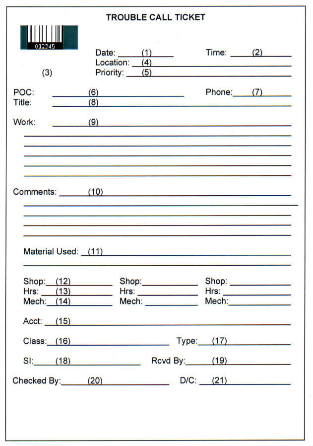
|
1.3. Instructions for Use. The Trouble Call ticket should be automated as part of the CMMS. Initial data entry can then be accomplished at a computer terminal by the work reception clerk as the work is received. In many cases requests will be received by telephone; however, they may be received by electronic mail where it is implemented. A Trouble Call ticket may be the means of issuing facilities maintenance work requested by other means, such as a request for facilities maintenance services (see paragraph 2, Request for Facilities Maintenance Services), or as the result of an inspection, when the scope of work is small. The following discusses use of the form.
a. The work order number is normally assigned by the CMMS; however, this can be accomplished manually. If it is assigned manually, it should be checked for duplications. The use of a bar code can speed subsequent processing and closing the Trouble Call ticket while reducing data entry errors. (Most CMMS support printing of bar codes.)
b. The work reception clerk enters the Date, Time, Location, Priority, POC, Phone, Title, and Work data. Normally, this information is obtained during the initial telephone request. The clerk must use the Center's priority system when assigning the priority. The Work data entry may take the form of a description of the problem or the desired end result; for example, "Door closer is broken" or "Fix leaking sink". The Work data entry also can include special coordination instructions or specific due dates. It is essential that the POC and Phone data entries be correct to permit the shops to obtain additional information, if required. Based on the foregoing information, the work reception clerk determines and enters the Scope, Type, SI (Special Interest), and Acct (accounting data). The clerk completes the form by entering the name or other identifier in the Rcvd By block. (Bar coding can expedite completion of the ticket by using a dictionary of standard terms, phrases, and other data available to the work reception clerk. The clerk can scan a bar code dictionary entry in lieu of typing a data field. This offers the dual advantages of reducing keyboard errors and using standard vocabulary for the data element.) Once this data is entered, the Trouble Call ticket is sent to the shops.
c. The shop supervisor reviews the Trouble Call ticket and assigns it to a mechanic for accomplishment, in accordance with its priority. Routine work is normally grouped by location and craft to minimize time lost in travel. In some cases a job may require specialized skills not found in the shop that normally performs Trouble Call tickets, in which case it is assigned to another shop for completion; for example, machining a special fitting.
d. The mechanic performing the work enters the work performed in the Comments area and the Material Used if material beyond that carried as bench stock or in preexpended bins is required. Alternatively, the Materials Used information may be obtained as part of a materials management module in the CMMS when the material is issued to the mechanic. Unusual conditions encountered are noted in the Comments block as well. The mechanic initials the form upon completion.
e. The shop supervisor enters the identification and the labor hours used on the Trouble Call ticket. The shop supervisor checks the completed form to ensure that all entries are made and returns it to the work control center to be closed. If the supervisor or other official inspects the competed work, this is indicated by initialing the Checked By block.
f. When the completed form is returned to the work control center, it is closed by entering the completion data in the CMMS. This will normally include labor and material expenditures, completion date, and applicable comments on work performed. The information becomes part of the maintenance history file. A hard copy of the Trouble Call ticket need not be retained if the data is stored in the CMMS and backed-up. If it is determined by the mechanic or supervisor that followup action is required, the work reception clerk enters the required action into the work control system. This may take the form of another Trouble Call ticket or a request for facilities maintenance services (see paragraph 2, Request for Facilities Maintenance Services).
2.1. Sample Form: Request for Facilities Maintenance Services. Figure C-2 is a sample form to be used by customers to document Service Requests or to request other facilities maintenance services. The primary purpose for this form is to document requests for work. The key factors are ensuring that sufficient data is obtained to identify, describe, and manage the work; that the work is properly authorized; that the work is properly tracked; and that accountability is maintained. The work may be accomplished as a Trouble Call ticket, a work order, or by separate contract, depending on its urgency, scope, and cost. The determination on how the work is accomplished is made as part of the facilities maintenance management process.
2.2. Data Elements
Data Fields |
Definition |
|
| 1. | Originator: | The name (or other identifier) of the requesting organization/customer. |
| 2. | Date: | The date the request is submitted. |
| 3. | POC: | Point of Contact, the name of the person to be contacted regarding the request. |
| 4. | Phone: | The telephone number for the POC. |
| 5. | Cust. No.: | Customer Number, an identification number assigned by the submitting organization. (This is optional, but it gives the originator the ability to assign the organizations own identification or tracking number.) |
| 6. | Location: | The facility number and any other pertinent data regarding the location where the work is to be done. |
| 7. | Priority: | The work priority rating. |
 |
| 8. | RCD: | Requested Completion Date, the completion date requested for the services. |
| 9. | Estimate Only: | An indicator that the originator wants a cost estimate for the work requested rather than immediate performance of the work. |
| 10. | Customer Signature:
| The signature of an individual authorized to submit requests from the requesting organization. (Other validation systems may be used, such as an authorization number if received by electronic mail.) |
| 11. | Requested Work: | A description of the requested work and a justification for the request if it is for other than maintenance. |
| 12. | Special Instructions: |
Any special permits, coordination, outages, or other requirements the originator is aware of that apply to this work. |
| 13. | WICN: | Work Input Control Number, a unique identifier assigned by the facilities maintenance organization to identify the request for subsequent tracking by the facilities maintenance organization. |
| 14. | Date Rcvd: | The date the request is received by the facilities maintenance organization work reception desk. |
| 15. | W.O. #: | Work Order number, the identifying number of the work order that the requested work is being accomplished under, if applicable. |
| 16. | Labor: | Estimated labor cost for the work. |
| 17. | Material: | Estimated material cost for the work. |
| 18. | Equipment: | Estimated equipment cost for the work. |
| 19. | Other: | Estimated other costs for the work. (This could include items such as one-time contracts for portions of the work.) |
| 20. | Total Est: | Total estimated cost. |
| 21. | Approval Status: | An indicator to document that fact that: (a) the work is approved and will be performed by the facilities maintenance organization using the funds cited in block 23, (b) is approved subject to funding by the originator, or (c) is disapproved. |
| 22. | Comments: | Additional information such as the reason for disapproval or a note regarding sketches or attachments to a returned estimate. |
| 23. | Fund Citation: | A fund citation or accounting data to cover the work. |
| 24. | Authorizing Signature: |
Signature by competent authority granting approval to charge the funds in the Fund Citation data field for the work. |
| 25. | Date: | The date the Authorizing Signature is affixed. |
| 26. | Internal
Status: | This information is not shown on the sample printed form, but should be contained in the CMMS database. It is a series of status tracking data fields used by the facilities maintenance organization. The status data includes the date and current processing status of the request as well as whom has the request for action and what actions have been completed. |
2.3. Instructions for Use. The Request for Facilities Maintenance Services should be automated as part of the CMMS; however, because it originates with a customer, entry into the CMMS may not take place until after it is submitted by the originator and received by the work control center. Where electronic mail is available or customers have network access to the CMMS, it may be possible to automate the submission and initial data entry. The form is used as follows:
a. The originator provides the required information for data fields 1 through 12, 23, 24, and 25. The remaining fields are the responsibility of the facilities maintenance organization. Normally, fields 1-12 are filled in at the time of the initial submission. The Estimate Only "Y" block is selected if the originator is requesting only a cost estimate.
b. When the facilities maintenance work reception desk, in the Work Control Center (WCC), receives the request, the work reception clerk enters the date received and assigns a work input control number for tracking purposes.
c. The WCC (typically the work reception clerk) screens the request to determine what action is required. If the request is for work properly accomplished as a Trouble Call ticket, the WCC prepares a Trouble Call ticket and notes this in the Work Order block (15) and the Comments block (22). The WCC notifies the originator by completing the Approval Status (21) and returning a copy to the originator./p>
d. If the request is for an estimate only, the WCC forwards it to the estimators. When the P&E's complete the estimate, they fill in the Labor, Material, Equipment, Other, and Total blocks (16-20) and return it to the WCC. The WCC notifies the originator by returning a copy of the request with the estimate data. The returned package may include the detailed estimate and job plan prepared by the P&E, a request for funds, and a tentative or conditional scheduling window for the work.
e. If the request is for the performance of work that requires planning and estimating and it has received preliminary approval, the WCC forwards it to the P&E's for detailed job planning and estimating. When the P&E's complete the job package (including a work order), they return it to the WCC. The WCC then forwards it to the proper official for final review and approval.
f. If approved, the WCC completes the Work Order #, Approval Status, and Comments blocks (15, 21, and 22) and notifies the originator. If the originator should fund the job, it proceeds as a request for estimate as discussed in paragraph 2.3d. The reasons for originator funding should be stated in the comments. If the originator provided funding data for the request, it is entered into the shop load plan for execution when final approval is given.
g. If the request is disapproved, the WCC enters this in the Approval Status and Comments blocks (21 and 22) and notifies the originator. Because disapproval's can cause customer discontent, the WCC should ensure review by an appropriate manager in the facilities maintenance organization before notifying the originator.
h. The Internal Status data elements (item 26, not shown on the form) are used to track the status and progress of the request. As the request moves through the facilities maintenance management process and facilities maintenance organization, the WCC enters the date, status, and responsible action party. This provides a history of the request.
3.1. Sample Form: Facilities Maintenance Work Order. Figure C-3 is a sample facilities maintenance work order form. The form is generic, but it illustrates the information recommended for a work order. The form shown in Figure 10-2, Equipment/Discrepancy Classification Form, also generic, can be used to identify work items, usually trouble call work, that do not have identification numbers. Using these standardized equipment terms and discrepancies will allow the work to be coded into the CMMS for data integration and analysis. Figure C-4 is a sample continuation sheet that supports the sample facilities maintenance work order form. Figure C-5 is a sample facilities maintenance work order material/equipment requirements form that can be used to document the materials and equipment required for the work order. The actual forms used should be tailored to the Center's needs and the CMMS used.
3.2. Data Elements
| 1. | W. O. #:
| Work Order number, this number is used to track the work order and related actions throughout its life. On the sample it is shown both as a bar code and as numerals. One work order may be issued to cover more than one work request. |
| 2. |
WICN: | Work Input Control Number, a unique number assigned by the facilities maintenance organization to identify a request for facilities maintenance services for subsequent tracking of the request. One work request may result in more than one work order. |
| 3. | Priority:
| The work priority rating. This may not be the same as the priority requested by the originator on the Request for Facilities Maintenance Services form. |
| 4. | RSD: | Required Start Date, the date work can or must start as applicable. This may be determined by the availability of the facility or the time required to meet the completion date. |
| 5. | RCD: | Required Completion Date, the required completion date for the work order. Where possible, this should be the same date as on the Request for Facilities Maintenance Services form. |
| 6. | Type: | The type of work as defined in paragraph 1.5.1.3(b) of Chapter 1 or locally. |
| 7. | SI: | Special interest, an indicator as defined in paragraph 5.5.3.4. of Chapter 5 or locally. |
| 8. | Class: | Class, a locally definable descriptor for the work that can be used for analysis of work. |
| 9. | Facility #: | The facility number as recorded in property records. |
| 10. | UDF: | User definable field, a locally definable descriptor for the work that can be used for analysis of work. |
| 11. | Accounting Data: | This is the applicable accounting data for the work order. |
| 12. | UDF: | User definable field, a locally definable descriptor for the work that can be used for analysis of work. |
| 13. | POC: | Point of Contact, the name of the customer organization's POC responsible for this request. This is needed by the shops for coordination purposes. |
| 14. | Phone: | The telephone number for the POC. |
 |
 |
| 15. | Equipment #:
| The equipment inventory number, as recorded in property records. This field applies only when the work is to be done on an equipment item. It can be the principal equipment item if the work order covers multiple equipment items. |
| 16. | Title: | Short descriptive title of the work order. |
| 17. | General Description: | A narrative description of the scope and intent of the work order. |
| 18. | Line #: | Sequential task numbers. |
| 19. | Shop: | Shop, the shop or craft group planned to perform the task. |
| 20. | Work Tasks: | A statement of each task required to complete the work order. |
| 21. | HRS: | Hours, the amount of labor required to complete the task. Normally, this is based on an estimating standard. |
 |
| 22. | Special Instructions: | Any special instructions or directions not covered in the listed work tasks. |
| 23. |
Continuation: | Statement that material and continuation sheets are provided where all tasks and material/equipment requirements are not entered on this form. Continuation sheets are forms that contain the work order number and additional work breakdown lines (see Figure C-4). |
| 24. | Sketches:
| Reference to drawings or sketches. Ideally, drawings would be from a graphics information system or CADD system that is integrated with the CMMS. The drawings, sketches, and other graphics would be prepared, printed, and attached to the work order. |
| 25. | Estimate
Summary: | This multi-field section is a summary of the work order estimate by shop, listing the estimated hours, labor cost, material cost, and total costs, together with any overall reservations for contingencies, overhead, or surcharges, and the total estimate. |
| 26. | Approved: | Signature authorizing release and execution of the work order. |
| 27. | Date: | Date the work order is approved for execution. |
| 28. | Estimate Basis: | A field to identify the basis of the cost estimate or the estimating standard used. |
| 29. | Completed: | The date the work order is completed. |
The work order material/equipment requirements form (Figure C-5) includes the following additional data elements:
| 30. | Item #: | Sequential number of item on the requirements list. |
| 31. |
Stock #: | The stock number of the required item. This may be a local stock number, a National Stock Number (NSN), a manufacturer's part number, or other identifier. If other than a local stock number or NSN, supporting information (e.g., the identity of the manufacturer) should be given with the description. |
| 32. | Description: | Nomenclature, supplier, and other descriptive data of the required item or equipment. |
| 33. | UM: | This multi-field section is a summary of the work order estimate by shop, listing the estimated hours, labor cost, material cost, and total costs, together with any overall reservations for contingencies, overhead, or surcharges, and the total estimate. |
| 34. | Qty: | Quantity required. |
| 35. | Unit Cost: | Unit cost of the item. |
| 36. | Total: | Total cost of the specified quantity of the item. |
| 37. | Avail: | Availability of the material. Enter the material delivery due date or a symbol to show that the material is in stock and ready for issue to the shops. |
3.3. Instructions for Use
a. The facilities maintenance work order form provides the work authorization and direction to the shops. It also documents the work phases and cost estimate. Except for the accounting data and approval signatures, the work order form, continuation form, and material/equipment requirements forms usually are prepared by the P&E's. Normally, the accounting data is assigned as part of the final approval process. The use of a bar code on the work order form, the work order continuation form, and the material/equipment requirements form speeds subsequent processing, material issue, and closing of the work order while reducing data entry errors. (Most CMMS support printing of bar codes.)
b. After the work order has final approval, it is distributed to the shops, the material manager, the customer (in the case of customer-requested work), and others as determined by Center policy. Distribution may be accomplished electronically if e-mail is available, or if the CMMS work order database is shared on a network. The form shown contains all information concerning the work order and goes beyond the information requirements of many users of the form. For example, the material manager may not need the detailed task breakdown. With electronic distribution it is possible for users to receive only necessary extracts of the data.
c. When the work order is completed, it is closed and the information is added to the facility history files. The completion date is recorded and reported to the work control center.
4.1. Sample Form: Shop Load Plan. Figure C-6 (see reproducible and enlargeable page at the end of this appendix) is a sample shop load plan form. The CMMS used by the Center should support computer-aided scheduling, including interactive manpower and other resource scheduling and schedule balancing. The shop load plan should be automated as a standard report in the CMMS. A single database should support all three levels of scheduling (i.e., shop load plan, master schedule, and shop schedule) in a networked system. While it is possible to examine the shop load plan on a video display terminal, the practical limitation on the number of lines and columns that can be displayed at one time makes a printout on wide paper convenient for use by managers.
4.2. Data Elements. The following data elements are shown on the Shop Load Plan. The information either is contained in the CMMS database or is derived from the CMMS database. It is defined below as an aid to understanding the schedule format. The only item that should require entry in the scheduling process is for the scheduling period. The rest of the information is based on other data entered in the CMMS during the work reception and planning process or extracted from other databases, such as labor accounting.
| 1. | Period
Covered: | The time period this schedule considers. Normally, for The Shop Load Plan this is a quarter; however, the immediate next three months may be subdivided into a 1-month short-term and a 2-month midterm load plan for additional scheduling control. |
| 2. | Shop: | The shop or craft group being scheduled; e.g., carpenters. (The sample form shows 12 shops; this should be adjusted to meet local needs.) |
| 3. | No. of Employees: | The average number of employees available in each shop |
| 4. | Gross Workhours Avail: | The total number of workhours available in each shop during the schedule period. |
| 5. |
Adjustments: | The number of workhours that will not be Available in each shop for facilities maintenance work due to leave, training, jury duty, and similar nonproduction activities. (This may be presented on more than one line if it is desired to have a line for each type of adjustment.) |
| 6. | Net Workhours Avail: | The net workhours available in each shop for facilities maintenance work, computed as item 4 less item 5. |
| 7. | TC LOE: | Trouble Call ticket Level of Effort (LOE), the number of hours allocated by shop for jobs issued under Trouble Call tickets. Usually, this is based on past experience. |
| 8. | PM Scheduled: | The number of hours for scheduled PM work by shop. This is determined from the PM schedule contained in the CMMS database. |
| 9. | PT&I Scheduled: | The number of hours for scheduled PT&I work by shop. This is determined from the PT&I schedule contained in the CMMS database. |
| 10. | Scheduled,
Recurring: | The number of hours by shop for other scheduled recurring work. This may be determined from the CMMS database. It may be presented on more than one line if grouped, such as by type or work order. |
| 11. | Total LOE Scheduled: | Total hours committed to items 7, 8, 9, and 10 above, etc: |
| 12. | Carry-over From Prior Period: | Work scheduled or started in the prior period, but not completed, and thus, carried over to this period. This may be automatically computed by comparing work order labor estimates against labor charges to date. |
| 13. | Available to
Schedule: | Net Workhours available (6) less item Total LOE Scheduled (11), and Carryover (12). This is the workforce available for scheduling new work orders. |
| 14. | W.O. #: | Work Order number for each work order listed. |
| 15. | Description: | An entry giving a short title for each work order. The number of hours estimated for each shop for the work order follows on the same line. |
| 16. | RSD: | Requested start date for the work order. |
| 17. | RCD: | Required completion date for the work order. |
| 18. | PRI: | Priority of the work order. |
| 19. |
MAT: | Material status indicator. Normally, this block contains the date on which the required material is expected to be available, or that the material is available. This is the overall status of the field "Avail" on the Work Order Material/Equipment Requirements form, Figure C-5. |
| 20. | Workhours: | The estimated workhours for the work order for each shop. |
| 21. | Total: | The total labor hours for the work order for all shops. |
| 22. | Labor: | Estimated total labor cost for the work order. |
| 23. | Mtl: | Estimated total material cost for the work order. |
| 24. |
Other: | Estimated total other cost for the work order. This would include items such as equipment rentals and contracted services. |
| 25. | Total: | The total cost for the work order. |
4.3. Instructions for Use
a. Normally, the shop load plan is prepared covering a quarter. However, shop load plans should be prepared and maintained looking 18 months into the future. The last period should include all work that is in an "estimated and approved but unscheduled" status. A Center also may wish to extract a short term (next month) and a midterm (following two months) shop load plan for closer work scheduling and management. After final approval of a work order, it is assigned to a shop load plan. Normally, this level of scheduling is done by a senior maintenance planner, not in the shops organization. This starts the work performance phase and triggers material acquisition to ensure that the required material is available for the assigned start period. Approved work orders remain in the shop load plan until completed or canceled.
b. The primary purpose of the shop load plan is to provide for the orderly scheduling of work in accordance with the Center's mission priorities, to assist in resource scheduling and management, and to provide senior managers with information on pending work. It also provides a valuable tool for evaluating the workforce skill mix against workload requirements. If the shop load plan consistently shows a significant amount of over scheduling or unscheduled backlog in a shop coupled with under scheduling in another shop, realignment of workforce assets from the under scheduled to the over scheduled shop may be in order.
5.1. Sample Form: Master Schedule. Figure C-7 (see reproducible and enlargeable page at the end of this appendix) is a sample form for a master schedule. The master schedule is based on the shop load plan. However, its focus is on scheduling work performance to a specific week and tracking material status of work orders that are due for master scheduling in the future according to the current and approaching shop load plans. Normally, master schedules are prepared covering 6 to 10 weeks into the future. Jobs with long-lead time material requirements may be scheduled further in the future. Of special interest is the Work Orders Waiting Material section. This is used to highlight the material status of work orders waiting material that need to start during the master schedule period covered.
5.2. Data Elements. The following data elements are shown on the master schedule form. As with the shop load plan, the information either is contained in the CMMS database or is derived from the CMMS database by manipulation and calculation. The data elements are defined below as an aid to understanding the schedule form. The only data that should require entry in the scheduling process is for the period during which the work order is being scheduled (normally, the specific workweek). The rest is based on other data entered in the CMMS during the work reception and planning process, the material management process, or extracted from other databases such as labor accounting.
| 1. | Period
Covered: | The time period this schedule considers. Normally, for the master schedule this is a workweek. |
| 2. | Shop: | The shop or craft group being scheduled; e.g., shop 01, carpenters. |
| 3. | No. of Employees: | The average onboard manpower in each shop during the schedule period. |
| 4. | Gross Workhours Avail: | The total number of workhours in each shop available during this period. |
| 5. |
Adjustments: | The number of workhours that will not be available for facilities maintenance work due to leave, training, jury duty, and similar nonproduction activities. This may be presented on more than one line if it is desired to have a line for each type of adjustment. |
| 6. | Net Workhours Avail: | The net available workhours for facilities maintenance work |
| 7. | TC LOE: | Trouble Call ticket level-of-effort, the number of hours allocated for jobs, usually issued under Trouble Call tickets. Usually, this is based on past experience. |
| 8. | PM Scheduled: | The number of hours for scheduled PM work. |
| 9. | PT&I Scheduled: | The number of hours for scheduled PT&I work. |
| 10. | Scheduled &
Recurring: | The number of hours for other scheduled or recurring work. This may be presented on more than one line if grouped, such as by type or work order. |
| 11. | Total LOE Scheduled: | Total hours committed to items 7, 8, 9, and 10. etc: |
| 12. | Available to Schedule: | Net Workhours Available (item 6) less item 11. This is the workforce available for scheduling specific work orders. |
| 13. | W.O. #: | Work Order number for each specific work order listed. |
| 14. | Description: | Entry giving a short title for each work order. Also, the number of workhours scheduled for the work order by each shop during this schedule period are entered under the shop number on the same line. |
| 15. | RSD: | Requested start date for the work order. |
| 16. | RCD: | Requested completion date for the work order. |
| 17. | PRI: | The work order priority rating. |
| 18. |
MAT: | Material status indicator. Normally, this entry is the date on which material required for the work order is expected to be available, or a code indicating that the material is currently available. |
| 19. | Total: | Total labor hours for the shops. |
| 20. | Labor: | Expended labor hours. The total labor hours used or scheduled for the work order prior to this schedule period. |
| 21. | Mtl: | Cumulative material cost of material used for work order. |
| 22. | Other: | Cumulative costs of other than labor and material used for the work order. This includes such items as equipment rentals and contracted services. |
| 23. | Total: | Cumulative total cost. |
5.3. Instructions for Use
a. The master schedule is used to direct and coordinate the execution of work in the shops. It provides the coordinating linkage between the shops on jobs involving more than one shop and it highlights the material status of pending work orders. Normally, it is maintained under the direction of the shop supervisor working in close coordination with the shop supervisors and the maintenance planners. Work is scheduled by assigning it to a specific workweek; the automation program used should perform all necessary calculations, including computing estimated carryover work and resources expended (or projected to be expended) up to the period under consideration.
b. It is essential for the master schedule to give close attention to balancing the work to each shop to ensure that all forces are productively employed. To this end, the master scheduler will assign labor hours to each scheduled job within available manpower and job phasing requirements.
c. While it is possible to examine the master schedule on a video display terminal, the practical limitation on the number of lines and columns that can be displayed at one time makes it difficult to see all work that is subject to scheduling. Accordingly, printouts on wide paper and wall-mounted scheduling boards normally are used to display job status.
6.1. Sample Form: Shop Schedule. A form for a shop schedule is provided as Figure C-8 (see reproducible and enlargeable page at the end of this appendix). The shop schedule provides the day-to-day scheduling/assignment of workers and equipment to work orders. It is used by the shop supervisor as an aid in scheduling personnel and shared equipment assets.
6.2. Data Elements. The following data elements are shown on the Shop Schedule form. The information either is contained in the CMMS database or is derived from the CMMS database by manipulation and calculation. The data elements are defined below as an aid to understanding the schedule form. The only data elements that should be entered during the scheduling process are the assigned hours for each work order and employee being scheduled. The remaining data elements should be provided by the computer based on other data entered in the CMMS during the work reception and planning process, the material management process, or extracted from other databases.
| 1. | Period
Covered: | The time period this schedule considers. Normally, for the shop schedule it is a specific day. |
| 2. | Shop: | The shop or craft group being scheduled; e.g., shop 01, carpenters. |
| 3. | Employee: | The name or other identifier of the worker being scheduled. |
| 4. | Gross Workhours Avail: | The total number of workhours available for each worker during this period, normally eight. |
| 5. |
Adjustments: | The number of workhours that will not be available for facilities maintenance work due to leave, training, jury duty, and similar nonproduction activities. This may be presented on more than one line if it is desired to have a line for each type of adjustment. |
| 6. | Net Workhours Avail: | The net available workhours for each employee for facilities maintenance work. |
| 7. | W.O. #: | Work order number for each work order listed. |
| 8. | Description: | An entry giving a short title for each work order. The hours assigned to each employee for each work order number follows on the same line under the employee's identification. |
| 9. | RSD: | Requested start date for the work order. |
| 10. | RCD: | Requested completion date for the work order. |
| 11. | PRI: | The work order priority rating. |
| 12. |
MAT: | Material status indicator. Normally, this is a code or symbol indicating that the material is currently available. |
| 13. | Total: | Total hours for all employees. |
| 14. | Labor: | Cumulative labor hours for the work order prior to this schedule period. This information is provided as part of the labor distribution/timekeeping process. |
| 15. | Mtl: | Cumulative cost of material used for the work order. |
| 16. | Other: | Cumulative cost of other than labor and material used for the work order. This includes such items as equipment rentals and contracted services. |
| 23. | Total: | Cumulative total cost. |
6.3. Instructions for Use. The shop supervisor in scheduling and managing craft personnel uses the shop schedule. It is typically prepared on a weekly basis for each day of the following week, based on jobs scheduled in the master schedule. The shop supervisor enters the hours each employee is scheduled to work on each assigned job for each day. The workforce availability is determined from leave, training, and related activities that are also scheduled through the shop supervisor.
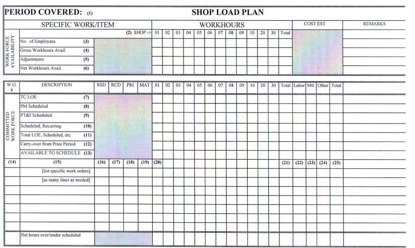
|
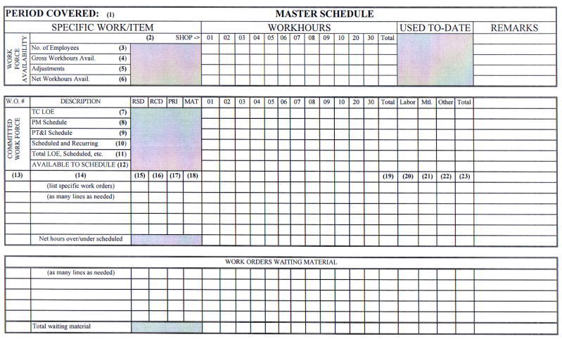
|
 |
This appendix includes sample computer screens for various facilities maintenance functions that may be included in a Center's CMMS. These samples are from a commercially available system and are presented as a sample of some of the types of data handling capability available.
The sample screens in Figures D-1 and D-2 are from an Operating Location application that allows the operator to enter and track locations of equipment and organize these locations into logical hierarchies or network systems. Operating locations are the locations in which equipment operates. Work orders can then be written either against the location itself or against the equipment in the operating location. Using locations allows for the tracking of the equipment's life-cycles (history) and provides the capability to track equipment's performance at specific sites.
Figure D-3 is a sample screen from an equipment module that allows the operator to keep accurate and detailed records of each piece of equipment. Accurate historical data can be used to help make cost effective replace or repair decisions. All equipment related data is available, such as bill of material, preventive maintenance schedule, service contracts, safety procedures, measurement points, multiple meters, inspection routes, specification data (name plate), equipment downtime, and related documents. This equipment data is used for managing day-to-day operations. The data can be used to develop additional management information, such as building equipment downtime failure code hierarchies to use in maintenance management metrics.
|
|
|
|
|
|
Figure D-4 shows the tag out screen of the safety plan module of this example system. With the emphasis placed of safety in NASA this module or similar capability is an important addition to the CMMS. This sample module provides the following capabilities:
a. Manual or automatic safety plan numbering.
b. Safety plans can be built ad-hoc for special work or defined for re-use in the Safety Plans application.
c. Track hazards for multiple equipment and locations.
d. Multiple precautions can be associated to a hazard.
e. Track hazardous materials for multiple equipment and locations.
f. Once hazards and precautions are entered, convenient pop-up list in this sample system is available for reference and data entry.
g. Track ratings for health, flammability, reactively, contact, and MSDS for hazardous materials.
h. Define lock-out/tag-out procedures.
i. Define tag identifications for specific equipment and locations.
j. Define safety plans for multiple equipment or locations.
k. View link documents.
l. Associate safety plans to job plans, to preventative maintenance masters and to work orders.
m. Safety plans are printed automatically on work orders.
n. Flexible business rules allows tag outs procedures to be associated to hazards OR directly to locations, equipment, safety plans or work orders.
o. Copy existing safety plans to new safety plans.
|
|
The Inventory Control application shown in Figures D-5 allows the operator to track inventory movement such as move items in or out of inventory, or from one location to another. Stocked, nonstocked, and special order items can be tracked. The application as shown in Figure D-5 also allows the tracking of item vendors, the locations where an item can be found, item cost information, and the substitute or alternate items that can be used if necessary.
Figure D-6 is a sample work request screen that could be used by anyone at a Center to input-request, such as trouble calls, or by work control to record-request. The simple to use data entry screen was designed for minimal data entry. The work order number is assigned manually or automatically. A requester would enter minimal data, as shown on the sample, with work control entering additional information as required. Data is entered once, and pop-up tables in this system eliminate the need to memorize codes. This computer system could be used by a Center in their CMMS rather than the Trouble Call Ticket shown in Appendix C.
The Sample Work Order Tracking Screen shown in Figure D-7 is the heart of a work order system. The data is entered once, and pop-up tables eliminate the need to memorize codes. This tracking system provides instant access to all of the information needed for detailed planning and scheduling, including work plan operations, labor, materials, tools, costs, equipment, blueprints, related documents, and failure analysis. Of course, this is dependent on how many modules have been installed and how much information has been entered in the system.
a. The Work Manager module in this example system lets the planner specify which labor to apply to specific work orders and when. It has two modes, Dispatching and Planning.
b. In the Planning Mode shown in Figure D-8, labor assignments are planned for future shifts. Each person's calendar availability is considered when the assignments are made. The assignments are created sequentially over the shift, filling each person's daily schedule with priority work for the craft. It can even split larger jobs over multiple shifts - automatically.
c. In the Dispatch Mode shown in Figure D-9 labor assignments are carried out as soon as possible. This system in this example can even begin tracking labor time from the instant the assignment is made. The system operator can interrupt work already in progress in order to reassign labor resources to more crucial work.
|
|
|
|
|
|
|
|
Figure D-10 shows a sample Quick Reporting screen that provides a rapid and easy means for opening, reporting on, and closing work orders, reporting work on small jobs after-the-fact, and even creating work orders on-the-fly. Labor, materials, failure codes, completion date, and downtime can all be reported on this one screen.
Sample preventive maintenance screens are shown in Figures D-11 and 12. The following capabilities provided in this sample system are listed to show how a CMMS can be utilized in managing a Center's PM program:
a. Supports multiple criteria for generating PM work orders. If a PM master has both time-based and meter-based frequency information the program uses whichever comes due first, and then updates the other.
b. Generates time-based PM work orders based upon last generation or last completion date. Next due date and job plans are displayed.
c. Permits and tracks PM extensions with adjustments to next due date.
d. Triggers meter based PMs by two separate meters.
e. Prints sequence Job Plans when wanted.
f. Creates a PM against an item so new parts have PMs automatically generated on purchase.
g. Specifies the number of days ahead to generate work orders from PM Masters that may not yet have met their frequency criteria.
h. Consolidates weekly, monthly, and quarterly job plans on a single master.
i. Assigns sequence numbers to job plans to tell the system which job plan to use when a PM work order is generated from a PM Master.
j. Permits overriding frequency criteria in order to generate PM work orders whenever plant conditions require.
k. Routes PMs with multiple equipment or locations.
l. Generates work orders in batch or individually for only the equipment wanted.
m. Can be used with the system Scheduler to forecast resources and budgets.
|
|
|
|
|
|
|
|
This appendix provides brief descriptions of the most commonly used predictive testing techniques, reference sources, detailed data sheets on those techniques that are considered state of the art, and applications of miscellaneous inspection techniques. Refer to the NASA Reliability Centered Maintenance Guide for Facilities and Collateral Equipment for a more comprehensive and detailed discussion of PT&I.
1.1 Vibration Analysis
a. Frequency and Time Domain Measurement. Analyzes the spectra of frequencies to identify the main causes of rotating equipment mechanical problems; (e.g., mechanical imbalance and misalignment).
b. Shock Pulse. Often used in evaluating the condition of bearings; measures the high-frequency noise generated when the moving elements in a bearing strike a defect and release mechanical energy.
c. Torsional Vibration Monitoring. Employs a pair of matched sensors to detect vibration of the equipment housing or structure caused by gear rotation and shaft torque.
1.2 Tribology and Lubricant Analysis (Condition Analysis)
a. Physical Analysis. Evaluates the color, appearance, and purity of a given oil, fuel, or grease sample to determine the presence of contaminants, breakdown of additives, corrosiveness, and viscosity.
b. Infrared Spectography. Compares new oil and fuel samples with samples that have been in service to determine the degree of degradation that has occurred.
1.3. Tribology and Lubricant Analysis (Wear Particle Analysis)
a. Direct Reading Ferrography. Measures the concentration of wear particles found in a fluid, segregates them by size using a graduated magnetic field, and trends the data.
b. Analytical Ferrography. After segregating wear particles, uses microscopic and other technical means to identify their types and compositions and then compares their characteristics with reference photographs to determine the severity of wear.
c. Magnetic Chip/Particle Counters. On-line systems that measure solid particles, ranging in size from 200 to 1,000 microns, in lubricating or hydraulic oil.
d. Graded Filtration/Micropatch. Passes a sample of the oil through a series of sequentially sized (graded) filters or a single micropatch and examines the filter or patch to determine the size and composition of particles in the sample.
1.4. Temperature Monitoring
a. Infrared Thermography. A noncontact technique employing either a video system or a scanning-type temperature probe that measures infrared radiation emitted and reflected from surfaces. The technique is also effective in detecting thermal cavities and roof leaks.
b. Contact Devices. Devices such as thermometers, resistance temperature detectors, thermocouples, decals, and crayons that detect temperatures within 0.25oC.
c. Deep-Probe Temperature Analysis. Using temperature probes inserted into the soil in the vicinity of buried pipes carrying steam or hot fluid to determine the degree of leakage and energy loss.
1.5. Electrical Testing
a. Megohmmeter Testing. Using a hand-held generator to determine the insulation phase-to-phase and phase-to-ground resistance from which the polarization index is calculated and the data trended to determine system degradation.
b. High Potential Testing (Highpot). Applies twice the operating voltage plus 1,000 volts to motor windings to test new and rewound motors. Caution is advised, because the test can induce premature failure.
c. Surge Testing. Using two capacitors and an oscilloscope to determine the condition of motor windings by measuring the current generated by applying a voltage pulse to two windings simultaneously. Like Highpot, applies a voltage equal to twice the operating voltage plus 1,000 volts, and consequently, it can induce premature failure.
d. Conductor Complex Impedance. Measures the total resistance of a conductor to detect motor coil degradations, worn or missing motor insulation, the presence of moisture, and other abnormalities.
e. Time Domain Reflectometry. Precisely locates cable faults by sending a fast-rise voltage pulse through a conductor and measuring the time delay in receiving a fault-caused reflected pulse.
f. Motor Current Signature Analysis. Using motor current spectra to determine if broken or cracked rotor bars or high-resistance end ring connections are present in motors.
g. Radio Frequency Monitoring. Monitors and trends radio frequency emissions from arching caused by broken windings in generators.
h. Power Factor and Harmonic Distortion. Determines the phase relationship between voltage and current, from which power factor is calculated and electrical power reduction decisions can be made.
i. Starting Current and Time. Measures the amount of current drawn, the sequence, and the time for equipment to come to operating speed to assess the operation of electrically driven equipment. For example, misaligned equipment may require more starting torque and, consequently, a higher peak and duration of startup current.
j. Motor Circuit Analysis. Combines several of the previously defined tests and factors to detect motor circuit voltage imbalances caused by such conditions as loose connections, corrosion, bad solder joints, and maladjusted contacts.
k. Insulation Power Factor Testing. Determines the phase relationship between the test currents and voltages. From this information, insulation impedance changes can be calculated and trended. Premature failures can then be predicted using operational and industry standards.
1.6. Leak Detection
a. Vibration Monitoring. Detects leaking steam traps by measuring vibration levels upstream, downstream, on the trap itself, and then comparing the vibration spectra.
b. Acoustic Emissions. Involves the use of two acoustic sensors that operate in the 100-200 kHz range to listen for sounds made by fault or failure conditions such as leaks in pressurized or vacuum systems.
c. Airborne Ultrasonics. Uses either contact or standoff devices, similar in purpose to stethoscopes, to detect emitted high frequency (over 20 kHz) sound as a fluid or gas flows through an orifice.
1.7. Flow Measurement
a. Doppler Shift. Measures flow rates by comparing the frequency shift between transmitted and reflected signals. Usually used in fluids with entrained particles or gas bubbles.
b. Time of Flight. Employs two transmitters and detectors separated by some predetermined distance and measures the difference in time of flight between upstream and downstream detectors.
c. Tracer Element. Inserts a tracer element in the fluid and measures the elapsed time and amount of dilution when the tracer element arrives at a predetermined downstream location.
1.8. Imaging
a. Macro Imaging. Employs fiber optics, endoscopes, borescopes, and miniature cameras to archive on film or to record digitally the actual condition of equipment and components.
b. Ultrasonic Imaging. Uses a pulse-echo thickness gauge to determine the presence of subsurface flaws, their size, and their orientation.
c. Radio Imaging. Uses portable x-, gamma-, or neutron-ray equipment to identify flaws; operates on the theory that the film will be darker where there is less wall thickness.
1.9. Corrosion Monitoring
a. Dew Point Monitoring. Calculates the dew point of a compressed gas system by determining pressure and temperature conditions within the system. When temperature drops below the dew point, water vapor condenses and corrosion increases.
b. Conductivity Monitoring. Measures the conductivity of ionic impurities in a fluid from which corrosion rates can be calculated.
c. Ultrasonic Corrosion Monitoring. Measures the thickness of metal ultrasonically by sending high-frequency sound waves into an object and measuring the amount of time for them to be reflected back.
1.10. Process Parameters/Visual Inspection
a. Diagnostic Monitoring. Recording process related data such as temperature and pressure and using changes in those parameters to identify emergence of a problem.
b. Visual Inspection. Visual detection of problems such as oil leaks that are not detected by other, more technical means.
1.11. Other Flaw Detection Techniques
a. Acoustic Emissions Detection. Uses special equipment to listen for sounds made by fault or failure conditions such as leaks in pressurized or vacuum systems. One application uses multiple sensors and computer algorithms to locate shear defects resulting from subsurface intragranular flaws. As these defects grow in size, they emit high frequency, highly directional noise in the 100-500 kHz range. Drawbacks in using this technique are (1) analysis is hampered by other noises in the same frequency range and (2) while this technology measures changes in the flaw size, it does not measure the size of the flaw itself.
b. Sulfur Hexaflouride (SF6). Finds leaks in systems by filling them with SF6 gas and then using special detectors to sense above-normal SF6 concentrations, which indicate the locations of the leaks.
c. Eddy Current Testing. Uses an induced magnetic field to detect cracks in metal test objects, such as heat exchanger tubes. Current flow caused by the magnetic field is reduced by electrical resistance at the defects and forms distinguishable current patterns. These patterns are then amplified and visually displayed allowing the analyst to determine both the flaw location and its size.
d. Liquid Penetrant Testing. Uses a low-viscosity liquid, penetrating dye and developer to penetrate and highlight surface defects.
e. Magnetic Flux. Magnetizes a specimen, causing fine, sprayed-on iron particles to concentrate at surface discontinuities.
f. Insulating Oil Test. Examines the oil properties such as dielectric strength, power factor, contaminant levels, acidity, and combustible gas content.
g. Replication. Makes a plastic foil casting of a portion of an item, then subjects the casting to microscopic examination. Defects such as stress cracks show up in the casting.
h. Electromagnetic Pipe Location. Locates and maps underground piping systems. It traces a piping system by directly applying or inducing a signal in the system and then uses an induction coil pickup to detect the signal.
i. Radar Mapping. Uses ground-penetrating radar to locate and map underground systems and to detect buried items.
j. Holographic Interferometry. Record deformations caused by stress or vibration. Determines degree of deformation by comparing the interference patterns that arise with normal conditions.
k. Boring. Bores holes into the tested item such as a utility pole and determines the item's condition by examining the shavings.
l. Holiday and Fault Location. Finds breaks in the insulation of piping and cable systems by detecting electrical signal leakage above the pipe or cable.
2.1. Vibration Analysis
a. Purpose
(1) Vibration analysis is used to detect, identify, and isolate specific component degradation and its causes prior to serious damage or actual failure. Vibration monitoring helps to determine the condition of rotating equipment, a system's structural stability, and sources of airborne noise.
(2) When equipment is known to be operating properly, its vibration baseline is established by taking vibration measurements at that time. Subsequent vibration readings can then be compared to the baseline, the components causing deviant readings can be identified, and the rate of component deterioration and the magnitude of any problems determined.
b. Techniques
(1) Frequency and Time Domain Measurement.
(2) Shock Pulse Analysis.
(3) Torsional Vibration Monitoring.
c. Applications
(1) All rotating and reciprocating equipment; i.e., motors, pumps, turbines, compressors, engines and their bearings, shafts, gears, pulleys, blowers, belts, couplings.
(2) Induction motors (to diagnose for broken rotor bars, cracked end rings, high-resistance connections, winding faults, casting porosity, and air-gap eccentricities).
(3) Structural support resonance testing, equipment balancing, faulty steam trap detection, and airborne noise measurements.
d. Effects
(1) Detects equipment component wear, imbalance, misalignment, mechanical looseness, bearing damage, belt flaws, sheave and pulley flaws, gear damage, flow turbulence, cavitation, structural resonance, and fatigue. Can provide several weeks or months warning of impending failure.
(2) When measurements of both amplitude and frequency are available, diagnostic methods (spectrum analysis) are used to determine both the magnitude of the problem and its probable cause.
(3) Vibration analysis systems are composed of microprocessor data collectors, vibration transducers, equipment-mounted sound discs, and a host personal computer with software for analyzing trends, establishing alarm points, and assisting in diagnostics.
e. Operators
(1) Requires personnel with the ability to understand the basics of vibration theory and possessing a basic knowledge of machinery and failure modes.
(2) Though site-dependent, usually one experienced vibration analyst plus two level I-trained technicians are sufficient.
f. Training Available
(1) Training is available through equipment vendors and the Vibration Institute, 6262 South Kingery Highway, Suite 212, Willowbrook, IL 60514, Internet: www.vibinst.org Phone: 630-654-2254; Fax: 630-654-2271.
(2) The Vibration Institute has published certification guidelines for vibration analysts. Passing a written examination is required for certification.
g. Cost
$30,000 to $70,000 for a single-channel, multi-channel, or on-line vibration datalogger (price varies with degree of technology), software, and primary training.
2.2 Tribology and Lubricant Analysis (Condition Analysis)
a. Purpose
(1) Oil analysis is used to determine the condition of a given oil, fuel, or grease sample by testing for viscosity; particle, fuel, and water contaminants; acidity/alkalinity (pH); breakdown of additives; and oxidation.
(2) Coupled with other technologies such as vibration and temperature measurements, oil analysis identifies the equipment condition and aids in identifying the root cause of failures.
b. Techniques
(1) Physical Analysis.
(2) Infrared Spectrography.
c. Applications
(1) Engines, compressors, turbines, transmissions, gearboxes, sumps, transformers, and storage tanks.
(2) Receipt inspection of incoming lubricating and fuel oil and grease supplies for condition, viscosity, and contamination.
(3) Spot-checking new, rebuilt, or repaired equipment as part of the acceptance process.
d. Effects
(1) Monitoring the condition of lubricants determines whether they are suitable for continued use or should be changed.
(2) Analysis of both the quantity and type of metal particle contamination in a sample can identify the specific component experiencing wear.
(3) Maintaining exceedingly clean lubricating fluids extends the life of bearings and other components. Maintaining proper acidity/alkalinity and the proper composition of additives keeps the corrosiveness of the lubricant in check.
(4) Lubricant monitoring protects equipment warranties that otherwise would not be honored based on manufacturer allegations that the equipment operated with contaminated oil.
(5) Use of oil analysis as part of the quality control associated with an equipment acceptance test will indicate if all lubrication or hydraulic systems were properly installed, cleaned, flushed, and filled with the appropriate lubricant.
(6) Long-term trending of oil analysis data can identify poor maintenance or repair practices that contribute to high maintenance costs, downtime, and reduced machine life.
e. Equipment Required
Extensive and expensive laboratory equipment is required for detailed analysis; thus, in-plant analysis is not justified. However, portable, stand-alone analyzers are now available for prescreening samples on site to determine if a more thorough or specific analysis is warranted.
f. Operators
One individual should be trained in tribology and should in turn train equipment operators and maintenance craft personnel on proper sample-taking techniques.
g. Training Available
Training is available from equipment vendors and from independent laboratories that perform oil analysis.
h. Cost
(1) "Free" to approximately $150 per sample, depending on the type of analysis desired, disposal fees, and the level of service provided by the vendor.
(2) $13,000 to $20,000 for equipment (on-site, stand-alone analyzer for prescreening) and tribology training.
2.3. Tribology and Lubricant Analysis (Wear Particle Analysis)
a. Purpose
(1) Wear particle analysis is a technique that determines the condition of a machine or machine components through examining particles contained in a lubricating oil sample. Wear particles are separated and subjected to ferrographic and microscopic analysis.
(2) Coupled with other technologies such as vibration and temperature measurements, wear particle analysis identifies the equipment condition and aids in identifying the root cause of failures.
b. Techniques
(1) Direct Reading Ferrography.
(2) Analytical Ferrography.
(3) Magnetic Chip/Particle Counters.
(4) Graded Filtration/Micropatch.
c. Applications
Engines, compressors, turbines, transmissions, gear boxes, etc.
d. Effects
(1) Analysis of both the quantity and type of metal particle contamination in a sample can identify the specific component experiencing wear, the magnitude of the wear, and the type of wear being experienced.
(2) Particle count indicates the effectiveness of existing filtration and measures overall system cleanliness.
(3) Long-term trending of oil analysis data can identify poor maintenance or repair practices that contribute to high maintenance costs, downtime, and reduced machine life.
e. Equipment Required
Extensive and expensive laboratory equipment is required for detailed analysis; thus, in-plant analysis is not justified. However, portable, direct-reading contamination monitors and analyzers are now available for prescreening samples on site to determine if a more thorough or specific analysis is warranted.
f. Operators
One individual should be trained in tribology and should in turn train equipment operators and maintenance personnel on proper sample-taking techniques.
g. Training Available
Training is available from equipment vendors and from independent laboratories that perform oil analysis.
h. Cost
(1) "Free" to approximately $150 per sample, depending on the type of analysis desired, disposal fees, and the level of service provided by the vendor.
(2) $10,000 to $20,000 for equipment (on-site, stand-alone analyzer for prescreening) and tribology training.
2.4. Temperature Monitoring
a. Purpose
(1) Noncontact- and contact-type devices are used to detect temperature variances in machines, electrical systems, heat transfer surfaces, and structures and the relative magnitude of those temperature variances. Large changes in temperature often precede equipment failure.
(2) Infrared thermography, in particular, is a reliable technique for finding roof leaks and determining the thermal efficiency of heat exchangers, boilers, building envelopes, etc.
(3) Deep-probe temperature analysis can detect buried pipe energy loss and leakage by examining the temperature of surrounding soils. The technique can be used to quantify energy loss and its cost.
(4) Temperature monitoring can be used as a damage control tool to locate mishaps such as fires and leaks.
b. Techniques
(1) Infrared Thermography (Noncontact).
(2) Contact Devices (Thermometers, Resistance Temperature Detectors, Thermocouples, Decals, and Crayons).
(3) Deep-Probe Temperature Analysis.
c. Applications
Heat exchangers; electrical distribution and control systems; roofing; building envelopes; direct-buried pipes carrying steam or hot water; bearings; conveyors; piping; valves; steam systems; air handlers; and boiler insulation, casing, and tubes.
d. Effects
(1) Temperature monitoring techniques are used to locate hot spots due to loose, corroded, or dirty electrical connections; friction; damaged or missing insulation; and thermal system cavities, leaks, and blockages.
(2) Infrared thermography successfully locates roof leaks and is used in energy conservation programs by locating sources of heating and air-conditioning losses through building envelopes.
(3) The use of deep probes for measuring soil temperatures near buried pipes will detect insulation system failures and leaks. With knowledge of soil properties, the losses can then be estimated. This technique requires knowledge of piping locations.
(4) Noncontact heat measurement can be done from a distance and will accurately measure temperatures on items that are hard to reach, such as power lines or equipment that is normally inaccessible.
e. Equipment Required
(1) Equipment ranges from simple contact devices such as thermometers and crayons to full-color imaging and computer-based systems that can store, recall, and print thermal images.
(2) The deep-probe temperature technique requires temperature probes, analysis software, and equipment to determine the location of piping systems.
f. Operators
(1) Operators and mechanics with minimal training can perform temperature measurements and analyses using contact-type devices.
(2) Because thermographic images are highly complex and difficult to measure and analyze, training is required to obtain accurate and repeatable thermal data and to interpret the data. With adequate training (level I and level II) and certification, this technique can be performed by electrical/mechanical technicians and/or engineers.
(3) Although deep-probe temperature monitoring is often contracted because of the technician's required familiarity with soil properties, this technique can be applied by maintenance personnel with adequate training.
. Training Available
(1) Training is available through infrared imaging system manufacturers and vendors.
(2) The American Society of Nondestructive Testing (ASNT), P.O. Box 28518, Columbus, OH 43228-0518, Internet: www.asnt.org has established guidelines for thermographer certification. General background, work experience, and thermographic experience and training are all considerations for certification.
h. Cost
(1) Point-of-use black-and-white scanners are less than $1,000. Full-color microprocessor systems with data storage and print capability range from about $25,000 up to $70,000.
(2) Average thermographic system rental is approximately $1,500 per week.
(3) Subcontractor services are approximately $1,000 per day; for deep probe temperature analysis, the cost for contract services ranges from $1,500 to $2,000 per day with $5,000 to $6,000 for the first day.
(4) Operator training costs are approximately $1,250 per week.
2.5. Electrical Testing
a. Purpose
(1) Electrical testing is used to measure the complex impedance of electrical conductors, starters, and motors and their insulation resistance. By various methods, it detects faults such as broken windings, broken motor rotor bars, voltage imbalances, cable faults, etc.
(2) Current, voltage, and power factor also are monitored to determine power quality and to form a basis for reducing energy costs.
(3) Coupled with other technologies such as temperature monitoring and ultrasound, electrical testing identifies equipment condition and aids in identifying the root cause of failures.
b. Techniques
(1) Megohmmeter Testing.
(2) High Potential Testing (Highpot).
(3) Surge Testing.
(4) Conductor Complex Impedance.
(5) Time Domain Reflectometry (TDR).
(6) Insulation Power Factor Testing.
(7) Motor Current Signature Analysis.
(8) Radio Frequency (RF) Monitoring.
(9) Power Factor and Harmonic Distortion.
(10) Starting Current and Time.
(11) Motor Circuit Analysis (MCA).
(Note: Highpot and surge testing should be performed only with caution. The high voltage being applied in these tests may induce premature failure of the units being tested. For that reason, they normally are not recommended for condition monitoring.)
c. Applications
Electrical distribution and control systems, motor controllers, cabling, transformers, motors, generators, and circuit breakers.
d. Effects
(1) Electrical testing is used to monitor the condition or test the remaining life expectancy of electrical insulation; motor and generator components such as windings, rotor bars, and connections; and conductor integrity.
(2) Electrical testing is used as a quality control tool during acceptance tests of electrical systems such as new or rewound motors.
(3) During equipment startup, electrical testing is used to check proper motor starting sequencing and power consumption.
(4) Electrical testing is used to monitor power factor so that improvements can be made in the interest of reducing electricity consumption.
e. Equipment Required
A full electrical testing program would include the following equipment: multimeters/volt-ohmmeters, current clamps, time domain reflectometers, motor current signature analysis software, and integrated motor circuit analysis testers.
f. Operators
Electricians, electrical technicians, and engineers should be trained in electrical PT&I techniques such as motor current signature analysis, motor circuit analysis, complex phase impedance, and insulation resistance readings and analysis.
g. Training Available
Equipment manufacturers and RCM consultants specializing in electrical testing techniques provide classroom training and seminars to teach their testing techniques.
h. Cost
(1) Equipment costs vary from $20 for a simple multimeter to more than $25,000 for integrated MCA testers. A full inventory of electrical testing equipment should range from about $30,000 to $50,000.
(2) Training averages between $750 and $1,000 per week.
2.6. Leak Detection
a. Purpose
Leak detection techniques measure the sound or vibration resulting from cavitation, flow turbulence, or influx (in the case of vacuum systems) or escape of gas or fluid.
b. Techniques
(1) Vibration Monitoring.
(2) Acoustic Detectors.
(3) Airborne Ultrasonics.
c. Applications
Piping and process systems, compressed gas and vacuum systems, boiler and heat exchanger tubes, steam traps, refrigeration systems, electrical switchgear, and rotating machinery.
d. Effects
(1) Leak detection techniques are used to detect gas, fluid, and vacuum leaks; locate areas of turbulent or restricted flow; and measure corrosion and erosion in piping and vessels.
(2) In addition to detecting leaks, ultrasonic technology also can be used to detect electrical switchgear malfunctions, gear noise, faulty rolling element bearings, and other harmful friction in plant equipment. Ultrasonic frequencies range between 20,000 and 100,000 kHz.
e. Equipment Required
(1) Ultrasonic monitoring scanner for airborne sound or ultrasonic detector for contact mode through metal rod.
(2) Vibration monitoring equipment (see section 2.1 of this appendix).
f. Operators
Maintenance technicians and engineers.
g. Training Available
Minimal training required.
h. Cost
Scanners and accessories range from less than $1,000 to about $8,000.
2.7. Flow Measurement
a. Purpose
Liquid or gas flow rates are measured using either intrusive or nonintrusive flow measuring devices to aid in determining the condition of heat exchangers, pumps, and other plant components.
b. Techniques
(1) Intrusive Flow Measurement Devices (Ventures and Pitot Tubes).
Note: Use of these devices may not be feasible because of hazards involved in breaching the integrity of the system being monitored.
(2) Nonintrusive Flow Measurement Techniques (Doppler Shift, Time of Flight, Tracer Elements).
c. Applications
Equipment instrumentation, pumps, heat exchangers.
d. Effects
(1) Flow measurement techniques are used to check the accuracy of instrumentation installed on equipment.
(2) Flow measurement techniques are used to determine pump and heat exchanger performance and whether scale buildup or fouling is affecting system efficiency.
e. Equipment Required
Required equipment for nonintrusive flow measurement is generally nonspecialized (e.g., flow meters, two pairs of transmitters and receivers, and dyes or other tracer elements).
f. Operators
Maintenance technicians and engineers.
g. Training Available
Minimal (on-the-job) training required.
h. Cost
Flow meters, transmitters and scanners can be purchased for less than $1,000.
2.8. Imaging
a. Purpose
Imaging techniques are used to monitor on film or other visual display the actual condition, including material flaws, faulty welds, and blockages, of equipment and facility components.
b. Techniques
(1) Macro Imaging.
(2) Ultrasonic Imaging.
(3) Radiographic Imaging.
c. Applications
High-pressure piping, tank walls, valve and pump casings, and shafts.
d. Effects
(1) Macro imaging employs fiber optics, endoscopes, borescopes, and miniature cameras to archive on film or to record digitally the actual condition of equipment and facility components.
(2) Ultrasonic imaging in its simplest form uses a pulse-echo thickness gauge that makes point measurements and determines the presence of subsurface flaws, their size, and their orientation.
(3) Radio imaging uses portable X-ray or gamma ray equipment to identify flaws; it operates on the theory that the film will be darker where there is less wall thickness.
e. Equipment Required
Imaging equipment consists of the following types: ultrasonic thickness gauges, flaw detectors, ultrasonic imageries, and video devices.
f. Operators
Imagining should be performed by technicians trained in nondestructive testing techniques.
g. Training Available
Training is available from equipment vendors. Additional information is available from the American Society for Nondestructive Testing (ASNT), P.O. Box 28518, Columbus OH 43228-0518, Internet: www.asnt.org.
h. Cost
(1) The cost of imaging equipment ranges from about $3,000 for ultrasonic thickness gauges to about $250,000 for ultrasonic imageries.
(2) Training costs vary, but average about $1,000 per week.
2.9. Corrosion Monitoring
a. Purpose
(1) Corrosion monitoring techniques are used to detect the presence of corrosion in a system and to monitor its progression so that its causes can be treated and damage repaired before it progressively damages other components and systems.
b. Techniques
(1) Dew Point Monitoring.
(2) Conductivity Monitoring.
(3) Ultrasonic Corrosion Monitoring.
c. Applications
Chilled water, condensate, and pure water systems; compressed air systems; boiler water interfaces; storage tanks.
d. Effects
(1) Corrosion monitoring techniques determine the conditions under which condensation is likely to take place (dew point monitoring), the amount of ionic impurities in a fluid (conductivity monitoring), and the rate at which corrosion is taking place (ultrasonic corrosion monitoring).
(2) By knowing the degree and cause of corrosion in a system, timely actions can be implemented to prevent or to control corrosive deterioration. These include the proper selection of materials, sound engineering design, dehumidification, use of neutralizing alkalis in an acidic environment, application of protective coatings, and the addition of inhibitors in anodic and cathodic reactions.
e. Equipment Required
(1) Dew point monitoring uses relatively simple devices such as temperature and pressure gauges and steam tables to determine water vapor pressure, temperature, and saturation temperature.
(2) Conductivity monitoring uses a low-voltage generator and probes and a volt-ohmmeter to determine the conductivity of the fluid being monitored.
(3) Ultrasonic corrosion monitoring requires an ultrasonic measuring device and a personal computer and software for downloading data for evaluation.
f. Operators
Maintenance technicians and engineers with an understanding of the causes and effects of corrosion.
g. Training Available
Minimal (on-the-job) training is required.
h. Cost
The cost of ultrasonic monitoring equipment is less than $ 5,000; software costs are approximately $9,000.
2.10. Process Parameters/Visual Inspection
a. Purpose
Knowledge of normal process-related factors such as pressure, temperature, amperage, flow data information, etc., for a given equipment item, coupled with visual inspection of the equipment often identifies the emergence of a problem not otherwise detected by other predictive technologies.
b. Techniques
(1) Diagnostic Monitoring.
(2) Visual Inspection.
c. Applications
Virtually all facilities and plant equipment.
d. Effects
(1) By recording process-related data such as temperature, pressure, etc., every time equipment operators and maintenance personnel operate, monitor, or repair an equipment system, the information can be stored in a database and support other predictive efforts in cause-and-effect analyses.
(2) Visual inspection is an effective predictive technique that may detect problems, such as an oil leak, not noticed by other more technical means. Visual inspections should be habitual and continuous.
e. Equipment Required
No specialized testing equipment is necessary.
f. Operators
Operators and maintenance technicians. Any observant individual can assist by notifying maintenance personnel of apparent problems.
g. Training Available
Minimal (on-the-job) training is required to become a trained observer.
h. Cost
None.
Listed below are the organizations that offer training and certification in PT&I technologies and reliability. This list is by no means complete, as changes in industry are occurring constantly.
AVO International Training Institute (All Electrical Certifications)
4555 Westmoreland Way, Dallas, TX. 75237
Phone: 214-330-3522; Fax: 214-333-0104
Internet: www.avo.com
Bently-Nevada Corporation
1617 Water Street
Minden, Nevada 89423
Phone: 800-227-5514
Computational Systems Inc. (CSI) (Vibration I, II & III, and IRT I & II)
835 Innovation Way
Knoxville, TN. 37932
Phone: 423-675-2400; Fax: 423-675-4726
Internet: www.compsys.com
Diagnetics Inc. (Vibration I, II & III)
5410 S. 94E Ave.
Tulsa, OK 74145
Phone: 800-788-9774
EPRI M&D Center (Electrical Testing Training)
3 Industrial Highway
Eddystone, PA 19022
Phone: 800-745-9982
Flir Systems (FSI) (IRT level I, II & III)
16505 SW 72 nd Ave.
Portland, OR 97224
Phone: 503-684-3731; Fax: 503-684-3207
Inframetrics Inc. (IRT level I, II & III)
16 Esquire Road
N. Billerica, MA 01862
Phone: 508-670-5555; Fax: 508-677-2702
Ludeca Inc. (Alignment Training)
1527 NW 89 th Court
Miami, FL. 33172
Phone: 305-591-8935; Fax: 305-591-1537
Internet: http://www.ludeca.com/
National Environmental Balancing Bureau (NEBB)
8575 Grovemont Ct.
Garthersburg, MD 20877
Phone: 301-977-3698
Internet: www.nebb.org.
PdMA Corporation (Motor Testing Training)
5909-C Hampton Oaks Parkway
Tampa, Fl 33610
Phone: 800-476-6463
Internet: www.PdMA.com
Predict/DLI (Vibration level I, II & III, Oil and Tribology)
9555 Rockside Road
Cleveland, OH 44125
Phone: 800-543-8786
Internet: www.predictDLI.com
Update International Inc. (Vibration level I, II & III)
2103 Wadsworth Blvd.
Denver, CO 80227-2400
Phone: 303-986-6761; Fax: 303-985-3950
VibraMetrics, (Vibration level I, II & III)
1041 Sherman Ave.
Hamden, CT 06514
Phone: 800-873-6748; Fax: 203-288-4937
4.1. Utility Systems: Compressed Air
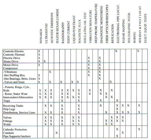 |
4.2. Utility Systems: Electrical
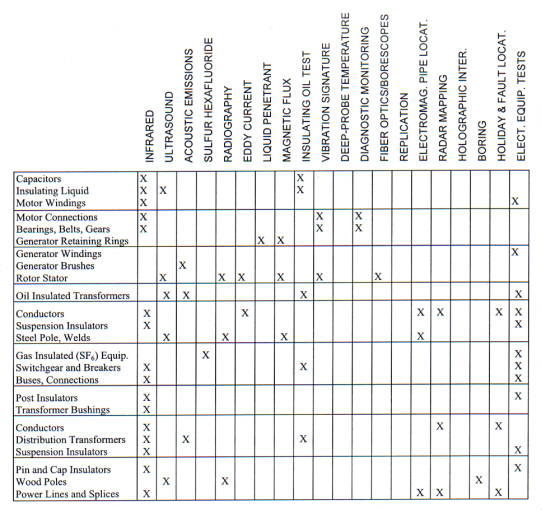 |
4.3. Utility Systems: Natural Gas
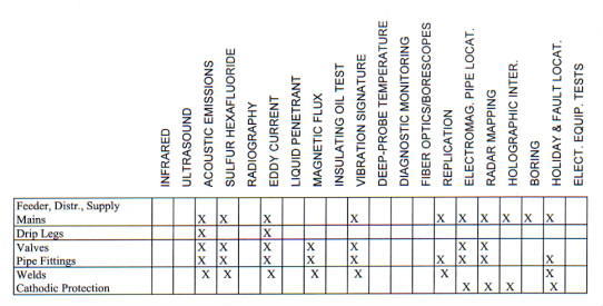 |
4.4. Utility Systems: Steam
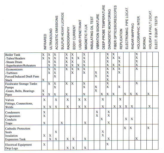 |
4.5. UTILITY SYSTEMS: HOT WATER
 |
This appendix provides maintenance management metrics from various sources. Centers and Component Facilities should consider their use, as applicable, as a means of measuring performance.
1.1 Facility Condition
The annual maintenance funding and resultant trends are a function of the BMAR and the needs of the Center. If the BMAR is high and increasing or staying the same, a positive trend would be observed. A downward trend would be expected if the backlog is low or decreasing. An elimination of the BMAR is not always possible or desirable since BMAR can provide an ability to balance resources in the long term. The following represent the applicable metrics and corresponding benchmarks:
a. Annual Maintenance Funding ($) should be between 2% - 4%. Current Replacement Value ($)
b. Annual Maintenance Funding ($) should show a downward or stabilized trend. Current Replacement Value ($)
1.2. Work Performance
The following metrics and corresponding benchmarks are used to trend work performance:
a. Emergency Trouble Call Response (hours) should show a downward trend.
b. Emergency Trouble Call Completion (hours) should show a downward trend.
c. Average Completion Time for Routine Trouble Calls (hours) should show a downward trend.
d. Average Completion Time for Repairs (days) should show a downward trend.
e. Jobs Completed as Scheduled (Number) should be 100%. Total Jobs Scheduled (Number)
f. Service Requests Completed (Number) should be 100%. Service Requests Committed (Number)
1.3. Work Element
1.3.1. The following metric may have a positive trend if repair rates are high, equipment/ facilities systems are not realizing their full useful life, and/or there is very little PT&I usage. A negative trend should develop if PT&I is increasing and repair rates are stable or decreasing. The benchmark is between 15% - 18%:
Preventive Maintenance ($)
Total Maintenance Cost ($)
1.3.2. The following metric should develop a positive trend as the maintenance program shifts from reactive and time-based maintenance to condition-based maintenance. The benchmark is between 10% - 12%:
Predictive Testing & Inspection ($)
Total Maintenance Cost ($)
1.3.3. The following metrics should develop a negative trend as the maintenance program shifts from reactive and time-based maintenance to condition-based maintenance:
a. Programmed Maintenance ($) should be 25% - 30%. Total Maintenance Cost ($)
b. Repair ($) should be 15% - 20%. Total Maintenance Cost ($)
c. Trouble Calls ($) should be 5% - 10%. Total Maintenance Cost ($)
1.3.4. The following metric should show an upward trend if a backlog of this type of work exists, and a negative trend if not much of this type work exists at the Center. The benchmark is between 15% - 20%:
Replacement of Obsolete Items ($)
Total Maintenance Cost ($)
1.3.5. The following metric should show a negative trend demonstrating increased focus on maintenance, and should be distinguished from customer reimbursed Service Requests. The benchmark is between 0% - 5%:
Service Requests ($)
Total Maintenance Cost ($)
1.4. RCM Performance Metrics
RCM analysis is an excellent indicator of performance.
1.4.1. Equipment Availability. The following metric is an indicator of equipment availability. The benchmark is 96%:
Hours Each Unit of Equipment is Available to Run at Capacity
Total Hours During the Reporting Time Period
1.4.2. Maintenance Overtime Percentage. The following metric is an indicator of maintenance overtime percentage. The benchmark is 5% or less:
Total Maintenance Overtime Hours During the Period
Total Regular Maintenance Hours During the Period
1.4.3. Emergency Percentage. The following metric is an indicator of the level of effort dedicated to emergency work. The benchmark is 10% or less:
Total Hours Worked on Emergency Jobs
Total Hours Worked
1.4.4. Percent of Candidate Equipment Covered by PT&I. The following metric is an indicator of the amount of candidate equipment covered by PT&I. The benchmark is 100%:
Number of Equipment Items in the PT&I Program
Total Equipment Candidates for PT&I
1.4.5. Percent of Emergency Work to PT&I and PM Work. The following metric is an indicator of the amount of emergency work relative to PT&I and PM work. The benchmark is 20% or less:
Total Emergency Hours
Total PT&I and PM Hours
1.4.6. Percent of Faults Found in Thermographic Survey. The following metric is an indicator of the percent of faults found through infrared thermography. The benchmark is 3% or less:
Number of Faults Found
Number of Devices Surveyed
1.4.7. Percent of Faults Found in Steam Trap Survey. The following metric is an indicator of the percent of faults found during steam trap surveys. The benchmark is 10% or less:
Number of Defective Steam Traps Found
Number of Steam Traps Surveyed
1.4.8. Ratio of PM/PT&I Work to Reactive Maintenance Work. The following metric is an indicator of the percentage of planned work relative to unplanned work:
A = 70% PM/PT&I
B = 30% Reactive Maintenance
where,
A%= Manhours of PM/PT & I Work Manhours of Reactive + PM/PT & I Work
B%= Manhours of Reactive Work Manhours of Reactive + PM/PT & I Work
A% + B% = 100%
The following metrics indicate how well the facilities maintenance budget is being executed:
a. Prior Year Execution ($) should be 100%. Prior Year Budget ($)
b. Current Year Expenditures to Date ($) should be 100%. Current Year Budget to Date ($)
h2>3. Other MetricsThe following are miscellaneous metrics used by organizations to measure performance. Their use by Centers is highly encouraged:
| a. | New Construction + Service Requests or New Work ($ or hours)
PM + PT&I + PGM + Repairs + ROI Maintenance ($ or hours) |
| should show a downward trend. | |
| b. | Repairs + Trouble Calls or Corrective Actions ($) PM + PT&I + PGM + ROI Preventive Actions |
| should show a downward trend. | |
| c. | Maintenance Backlog (BMAR) ($) should be less than 5% CRV ($) |
| d. | Average Age of Equipment (years) should show a downward trend. Average Useful life of Equipment (years) |
| e. | The number of disabling accidents per year should show a downward trend. |
| f. | The number of routine trouble calls per year should show a downward trend. |
| g. | The number of Work Orders per year or month should show a downward trend. |
| h. | The number of emergency trouble calls per year or month should show a downward trend. |
| i. | Customer Satisfaction, as measured by a numerical grade assigned to positive or negative feedback should show a positive, or upward, trend. |
| j. | The number of unplanned electric power outages should show a downward trend. |
| k. | The number of environmental violations should be zero. |
| l. | The number of OSHA violations should be zero. |
| m. | Maintenance Overtime (hours) should be less than 10% of payroll costs. Total Maintenance (hours) |
| n. | PM's Completed (number) should show an upward trend. PM's Scheduled (number) |
| o. | Scheduled Work (hours) should not exceed a locally determined benchmark. Total Work (hours) |
| p. | Actual Cost of Work ($) should be ¦ 10%. Estimated Cost of Work ($) |
| q. | Jobs Planned and Estimated (number) should not exceed a locally determined benchmark.
Total Jobs (number) |
| r. | Jobs Planned and Estimated ($) should not exceed a locally determined benchmark.
Total Jobs ($) |
| s. | Requisitions Met from Stock (number) should not exceed a locally determined benchmark.
Total Requisitions (number) |
| t. | Requisitions not in stock (number) should not exceed a locally determined benchmark.
Total Requisitions (number) |
| u. | Supervision (hours) should be less than 10%. Direct Labor (hours) |
| v. | Downtime Caused by Breakdown (hours) should not exceed a locally determined benchmark. Total Downtime (hours) |
| w. | Breakdown Labor (hours) should show a downward trend. Total Labor (hours) |
| x. | Maintenance Cost ($) should not exceed a locally determined benchmark.
Center Mission Cost ($) |
| 3.1. | The following two metrics must be carefully used and on a job-by-job or like-work basis. This may create conflict between shops and management. Care should be exercised to preclude adversarial relationships between the shops and management. |
| a. | Actual Hours per Job (hours) should be ¦ 10%. Scheduled Hours per Job (hours) |
| b. | Maintenance Work Orders Completed (number) should show an upward trend. Maintenance Work Planned & Scheduled (number) |
| 3.2. | The following two metrics should be trended with the locally accepted employment index factor: |
| a. | Material Cost ($) should not exceed a locally determined benchmark. Direct Labor Cost ($) |
| b. | Maintenance Cost ($) should not exceed a locally determined benchmark. Total Maintenance Workhours (hours) |
| 3.3. | Metric 3.2.b., when evaluated with metric 3.3.a. below, will help determine peaks of work resulting from the Center mission or weather related work. This evaluation can help in the planning process and use of alternative labor or contract methods. |
| a. | The monthly cost of maintenance operations should not exceed a locally determined benchmark. |
| b. | Equipment Covered by PT&I (number) should show an upward trend. Items of Equipment Potential for PT&I (number) |
| 3.4. | A downward trend of the spare parts inventory is desirable provided that the maintenance response time and completion times are not adversely affected. Given that, the desired metric is the following: |
| a. | The inventory value of spare parts should show a downward trend. |
NASA has adopted a maintenance philosophy that emphasizes using the optimal mix of strategies to provide required facility availability and reliability at minimum cost in order to support current and planned NASA programs.
One of the recognized deficiencies in complying with this philosophy is the lack of an effective long and short range planning process at most of the Centers and their Component Facilities across NASA. Since all the Centers are moving towards a fully implemented Reliability Centered Maintenance (RCM) program, the next step is to provide them with a vehicle to display long and short range facility requirements in a manner that can be used to articulate needs based upon mission impact and most probable facility availability outcomes under varying budget scenarios.
This document provides an Annual and 5-year Maintenance Work Plan template. A business plan approach has been used to integrate smoothly into NASA's strategic management process, afford Center Facility Management (FM) and senior managers the ability to make risk-based decisions regardless of the budget environment, and also allow Center FM organizations to pursue and measure their continuous improvement efforts.
Factors considered in developing the template include NASA's Integrated Financial Management Program (IFMP) and full-cost accounting; the asset management initiative; Performance-based Contract (PBC) conversion initiative, implementation of ISO 9000 quality process requirements into the NASA business; and Agencywide metrics requirements recently incorporated in the facilities maintenance self-assessment policy.
This is a template, a suggested approach to structuring (format and content) an Annual and 5-year Maintenance Work Plan. It has been designed to assist Center FM managers in preparing sound strategies, performing risk-based management and identifying the required resources to help enable Center and Agency goals. Center FM managers have maximum flexibility in tailoring the plan to meet individual Center needs.
Funding throughout the Plan is based upon current year dollars. All funding amounts within any category should reflect fully loaded (that is, all support costs) funds. For example, if a NASA contractor is developing their Plan, which may become part of a larger Plan, then all funding should reflect the fully loaded price to NASA. The fully loaded price would include all costs and fees (profit). In some cases, the Plan will reflect contract fixed prices.
Funding needs are developed within the Requirements Analysis section. When coupled with criticality issues, such as affect on Mission or Safety, it becomes an effective tool for identifying work which cannot be accomplished if the budget is reduced, as well as the highest priority backlogged work which could be accomplished if additional resources were made available.
The Annual Work Plan (AWP) is the first year, or base year, of this Plan. The base year information must be as complete and accurate as possible. In addition, the base year must identify work that will be deferred if the proposed budget is not completely funded and the effect on the Center/Facility if that work is not performed. The out-years, beyond the base year, are estimates that will form the basis of future AWP's.
NOTE TO AUTHOR: The Executive Summary will summarize the long and short-term goals and funding requirements for the facilities maintenance organization. The objective is to present the" big picture" including any requirements that cannot be accomplished within the established budget guidelines. Any adverse trends that could effect facility availability need to be described along with their probability of occurrence and their effects on safety, mission, or other costs. This is the opportunity for you to clearly articulate potential problems from reduced funding and the adverse impact they could have on mission support. If space allows, describe new initiatives and objectives, successes achieved to date, other initiatives outside of facilities maintenance, and funding requirements to continue them.
An effective Executive Summary should be short and concise. A good length is two to five pages. The goal is no surprises. If it is important it should be mentioned here. You must provide details, somewhere within the Plan, for every item mentioned in this summary. The details are backup information, a table or appendix, or a reference to other Center data.
All funds are in actual/current year $ (identify if k$ or M$).
| Funding | Actual | Projected |
| Source | FY(X-2) | FY(X-1) | FY(X) | FY(X+1) | FY(X+2) | FY(X+3) | FY(X+4) |
| ROS | |||||||
| R&D | |||||||
| Other | |||||||
| Other | |||||||
| Total |
NOTE TO AUTHOR: The funding chart above will show "big picture" funding for all Fund Sources (FS) received in current and previous fiscal years as well as proposed for the 5-year period. The NASA Financial Management Manual (FMM) provides details regarding funding sources. The FMM can be examined using the internet(www.hq.nasa.gov/fmm/). Adverse trends depicted in the chart should be identified and there impact on mission support described. The text that follows provides an example of what could be included in this section.
The term "Center" is inclusive of its' Component Facilities, as applicable.
The funding history and projected requirements to support facility maintenance for <INSERT CENTER NAME> are shown above. The funding for <INSERT CATEGORY> has been <INSERT "INADEQUATE," "FALLS SHORT" ETC.> and has resulted in <INSERT ADVERSE AFFECTS>. If additional funding is not made available <INSERT POTENTIAL FUTURE PROBLEMS>.
The following chart, together with backup details, is the proposed <INSERT CENTER NAME> Annual Work Plan for the upcoming fiscal year.
All funds are in current year $ (identify if k$ or M$).
| Work Element | FY<X> | % Effort | FY<X + 1> | % Effort |
| PM/PT&I | ||||
| Grounds Care | ||||
| PGM | ||||
| Repair | ||||
| Trouble Calls | ||||
| ROI | ||||
| Plant O&M | ||||
| Subtotal | ||||
| BMAR | ||||
| Special Programs | ||||
| Service Requests | ||||
| Subtotal | ||||
| CoF - Discrete | ||||
| CoF - Minor | ||||
| Total | 100 | 100 |
NOTE TO AUTHOR: The chart above should show all NASA categories of work and all other categories of work to be managed by the facilities maintenance group. The Work Element column in the chart can include any number of items. Keep in mind, to be effective, the chart should limit the items by rolling up funds from the details contained within this Plan. Backup details of specific requirements within each Work Element item should be available in an appendix, within the Plan or in a specifically referenced document or source. The percent effort refers to the percentage of overall effort that particular category represents. Include other charts and graphs to highlight performance and new initiatives. Include pictures here, and in the body of the Plan, if they add value.
NOTE TO AUTHOR: The following section is an overall assessment of past, present and future funding trends, anticipated needs, and the ability of current budget estimates to meet needs required to successfully support the Center mission. This section is a summary of Section 4.3 and Appendix F. An example of information that can be portrayed is shown below.
<INSERT CENTER NAME> mission is to <INSERT MISSION> and is NASA's Center of Excellence for <INSERT COE RESPONSIBILITY>. Facilities maintenance organization's vision and mission are <INSERT VISION AND MISSION>. Major active facilities maintenance programs include <INSERT MAJOR PROGRAMS TO SUPPORT MISSION>. Future Center programs planned include <INSERT FUTURE PROGRAMS PLANNED>. The current State of <INSERT CENTER NAME> facilities for providing the required reliability and availability to support these programs is <INSERT "GOOD," "FAIR," "MARGINAL," OR"POOR" >.
The current budget <INSERT EITHER "MEETS" OR "FALLS SHORT" > of anticipated needs to ensure facilities maintain a reasonably high probability of supporting current mission needs. <INSERT THE FOLLOWING APPROPRIATE ITEMS WHEN REQUIREMENTS ARE GREATER THAN RESOURCES AVAILABLE - "THE FOLLOWING IDENTIFIES ACTUAL RESOURCE REQUIREMENTS, RESOURCE SHORTFALLS, REQUIRED WORK WHICH CANNOT BE ACCOMPLISHED WITHIN THE AVAILABLE BUDGET, AND POTENTIAL MISSION IMPACT OF NOT ACCOMPLISHING THE REQUIRED WORK:" >
Preventive/Predictive Maintenance - <IDENTIFY RESOURCE REQUIREMENTS, RESOURCES BUDGETED, REQUIREMENTS WHICH CANNOT BE ACCOMPLISHED, AND SHORT AND LONG TERM PROJECTED MISSION IMPACTS>
Programmed Maintenance - <SAME AS PM/PT&I>
Repairs - <SAME AS PM/PT&I>
Replacement of Obsolete Items - <SAME AS PM/PT&I>
Utility Plant Operations - <SAME AS PM/PT&I>
Grounds Care - <SAME AS PM/PT&I>
Proactive Maintenance - <IDENTIFY COST EFFECTIVE METHODS REQUIRED TO MINIMIZE FAILURES NOT ABLE TO BE ACCOMPLISHED DUE TO BUDGET SHORTFALLS AND THE POTENTIAL SHORT AND LONG TERM IMPACTS>
Special Programs - <INSERT SPECIAL PROGRAMS NOT ABLE TO BE ACCOMPLISHED DUE TO BUDGET SHORTFALLS AND THEIR BENEFITS AND POTENTIAL IMPACTS ON CAPABILITY TO SUPPORT MISSION>
CoF Repairs/Revitalization - <IDENTIFY CURRENT YEAR NEEDS, FUNDED PROJECTS, AND POTENTIAL IMPACT OF UNFUNDED PROJECTS>
Backlog of Maintenance and Repair (BMAR) is currently at <INSERT $$ VALUE> or <INSERT %> of Current Replacement Value (CRV), and is expected to increase/decrease by <INSERT VALUE> in the coming year due to <INSERT PRIMARY CAUSE>. Primary mission impacts of existing BMAR are as follows:
1. <INSERT MOST SIGNIFICANT IMPACTS>.
2. ETC.
Facilities systems having a high probability of incurring unplanned downtime due to system condition and the most probable mission impact are as follows:
<INSERT SYSTEM #1 AND PROBABLE IMPACT>.
2. ETC.
Facilities systems having a medium probability of incurring unplanned downtime due to system condition and the most probable mission impact are as follows:
<INSERT SYSTEM #1 AND PROBABLE IMPACT>.
2. ETC.
| 1.0 | Introduction............................................................................................................................................ |
| 2.0 | Center Mission........................................................................................................................................ |
| 3.0 | Requirements Analysis........................................................................................................................... |
| 3.1 | Requirements by Builing or Area.......................................................................................................... |
| 3.2 | Requirements for Broad Center Support ............................................................................................ |
| 3.3 | 5-year Funding Plan ............................................................................................................................... |
| 4.0 | Facilities Maintenance.............................................................................................................................. |
| 4.1 | Maintenance Organization...................................................................................................................... |
| 4.2 | Maintenance Performance....................................................................................................................... |
| 4.3 | Budget Shortfall........................................................................................................................................ |
| Appdx A: | Abbreviations and Acronyms................................................................................................................... |
| Appdx B: | Definitions.................................................................................................................................................... |
| Appdx C: | Center Function Categories...................................................................................................................... |
| Appdx D: | Developing System Criticality .................................................................................................................. |
| Appdx E: | Sources of Data ........................................................................................................................................... |
| Appdx F: | Budget Shortfall/Plus-Up Planning Sheet ............................................................................................... |
| Appdx G: | Long Term Budget Planning Sheet.......................................................................................................... |
NOTE TO AUTHOR: This section of the Annual and 5-year Maintenance Work Plan provides the opportunity to explain to "outsiders" what the Plan is, why it was prepared and how it can be used. The text that follows provides examples of subjects that may be included in this section.
The term "Center" is inclusive of its Component Facilities, where appropriate.
This document describes the Annual and 5-year Maintenance Work Plan (the Plan) for <INSERT CENTER NAME> and represents a business plan for the facilities maintenance organization. The Plan identifies long term and short term maintenance requirements, describes the resources available and required to manage and accomplish facility maintenance, outlines the maintenance philosophy and approach for <INSERT CENTER NAME>. Further, it will allow managers to make risk-based decisions on the work to be accomplished regardless of the budget environment and it identifies specific areas to improve the overall effectiveness of facility maintenance. Overall effectiveness means PROVIDING THE REQUIRED FACILITY AVAILABILITY AT THE LOWEST COST. The Plan identifies metrics to be used in tracking progress towards accomplishing these improvements. The AWP is the first year, or base year, of this Plan. The out years, beyond the base year, are estimates that will form the basis of future AWPs.
Throughout this document, the term maintenance is used to represent the compilation of activity undertaken to ensure the required facility availability at the lowest cost. That activity includes: traditional maintenance, work done to reduce the probability of failure; repair, the restoration of function following failure; custodial, work done to maintain appearance or sanitation; and some operations. Sometimes it is difficult to place a single activity within one of the above categories. For example, painting provides both a failure prevention and appearance function. In addition, often the most effective maintenance approach is based upon monitoring a system or machine condition and performing some activity based upon that condition. Is the resultant activity maintenance or repair? This document will provide guidance for working through these issues. The activities include all of the elements identified in NPG 8831.2, Facilities Maintenance Management Abbreviations and acronyms are contained in Appendix A. Other definitions, which are based on the NPG, other NASA documents, and discussions with NASA personnel, are contained in Appendix B.
Facilities maintenance at <INSERT CENTER NAME> is absolutely crucial in ensuring facility availability for our critical missions. The effect of reduced maintenance is not always felt immediately. It is therefore essential that we have sufficient management information to plan short-term and long-term maintenance requirements properly, recognize adverse funding trends, make the right decisions on what work is not accomplished and be able to articulate the effect of reduced maintenance on facility availability and the mission.
The Plan builds upon <INSERT CENTER NAME> existing mission statements to develop guidance on categorizing facilities and equipment in terms of their criticality and current condition and considers long range plans that will affect real property assets and future maintenance requirements.
NOTE TO AUTHOR: This section of the Plan builds upon the Center mission, defines the facilities supported and their priority relative to that mission, and looks at long-term facility changes to support the mission. Sample statements are provided below.
The <INSERT CENTER NAME> mission is <INSERT MISSION> and is NASA's Lead Center of Excellence for <INSERT COE RESPONSIBILITY>. The key mission elements at <INSERT CENTER NAME> that directly and indirectly effect facilities are:
<DEFINE KEY ELEMENTS THAT EFFECT FACILITIES, BASED ON THE CENTER'S STRATEGY TO IMPLE MENT THE MISSION>.
NOTE TO AUTHOR: Categorize facilities (Table 2-1) in terms of mission criticality (determined in partnership with site users and managers), square footage and CRV for comparison/analysis purposes. One way to do that is to identify the entire Center by core or support function categories. The following terms, currently being considered for use Agencywide, are suggested:
Mission Critical: A building, area, or system that is critical to the Center mission or essential for Center of Excellence performance.
Mission Support: A building, area, or system, which provides support to the Center primary mission or Center of Excellence assignment.
Center Support: A building, area, or system, which supports the overall operation of the Center but does not meet the Mission Critical or Mission Support criteria.
An example of how to collect and categorize the facilities is provided in Appendix C. An appendix is useful for providing detailed information that is summarized in tables in this section. A map of the Center may also be useful to identify building and area locations.
NOTE TO AUTHOR: Describe any specific requirements that will drive your priorities or philosophy of maintenance accomplishment. Describe any known mission changes, funded or unfunded, that will impact existing or future maintenance requirements. Information may be available from the Installation Master Plan which is prepared and maintained by the Facilities Planning Office. Describe new facilities or facility modifications/repairs that will increase or decrease current maintenance requirements. Sample statements are shown below.
Over the next <INSERT TIME PERIOD>the following known mission changes will have the following impact on maintenance responsibility:
<INSERT KNOWN MISSION CHANGES AND THEIR EXPECTED INCREASE AND/OR DECRESE IN MAINTENANCE RESPONSIBILITY>
Additionally the scope of maintenance coverage will be <INSERT INCREASES DECREASES IN TOTAL AREA TO BE MAINTAINED, BUILDINGS OR AREAS THAT WILL BE BUILT, MODIFIED, BECOME REACTIVATED OR INACTIVE>.
Table 2-1 categorizes facilities in terms of mission criticality, square footage and CRV for comparison analysis purposes.
NOTE TO AUTHOR: Buildings/Areas are based on detailed breakdown (usually in an appendix). Space is gross floor space and does not include Grounds (which may be separately identified). CRV is in base year $ and includes noncollateral equipment (collateral and noncollateral may be separately identified).
| Mission | Actual | Projected |
| Category | FY(X-2) | FY(X-1) | FY(X) | FY(X+1) | FY(X+2) | FY(X+3) | FY(X+4) |
| Mission Critical | |||||||
| Building/Areas (No.) | |||||||
| Space (gross sq. ft.) | |||||||
| CRV ($) | |||||||
| Mission Support | |||||||
| Building/Areas (No.) | |||||||
| Space (gross sq. ft.) | |||||||
| CRV ($) | |||||||
| Center Support | |||||||
| Building/Areas (No.) | |||||||
| Space (gross sq. ft.) | |||||||
| CRV ($) | |||||||
| Totals | |||||||
| Building/Areas (No.) | |||||||
| Space (gross sq. ft.) | |||||||
| CRV ($) |
Note: Space is gross floor space and does not include Grounds. CRV is in base year $ and includes noncollateral equipment.
NOTE TO AUTHOR: Identify the staffing of the Center. This may provide an indication of the level of work being performed at the Center. The people may be NASA civil service, other Government civil service, or contract personal. For Fixed Price contracts, personnel figures may not be available or meaningful. A table, similar to the one below, is often effective.
Table 2-2 identifies the actual and projected staffing requirements at <INSERT CENTER NAME>
Numbers are Full-Time Equivalent people.
| Staff | Actual | Projected |
| Source | FY(X-2) | FY(X-1) | FY(X) | FY(X+1) | FY(X+2) | FY(X+3) | FY(X+4) |
| NASA | |||||||
| Other Gov. | |||||||
| Contract or | |||||||
| Contract or | |||||||
| Total |
NOTE TO AUTHOR: This section is used to develop facility maintenance requirements. Because each center is unique in its mission, physical plant and available resources, the method used in determining requirements will vary. In order to accurately identify overall maintenance requirements, key information will need to be available. Some examples of this information include (1) clear identification of the assets to be maintained (facilities and equipment); (2) their relative importance from a mission/safety/cost standpoint; and, (3) indicators of their current material condition from PT&I data and routine or special testing, operational performance data, failure rates, or, in some cases, visual presentation. Comparison to historical funding information will indicate any potential funding shortage and identify backlogs. For all elements defined in this section, you may need to develop an appendix, or reference data outside the Plan, that will document a source. Estimates, when used, should be clearly identified. Tables have been developed for this section to identify maintenance funding equirements and to articulate those needs throughout the organization. It is important that your Plan build upon the suggested elements, adding and deleting as needed, and settle on a final array of needed data. When that is completed, you can call upon the people who have the facility knowledge, to provide the data. This template builds upon the information and definitions detailed in NPG 8831.2, Facilities Maintenance Management. Expansion of definitions or clarification of information is provided when necessary to help in formulating your Plan.
This Section identifies the facility maintenance requirements at <INSERT CENTER NAME>. The Tables that follow identify the assets (facilities and equipment) that must be maintained, their relative importance to the mission of <INSERT CENTER NAME>, and their current condition, operational performance data and failure rates. Historical funding data, including funding shortfalls and consequent maintenance backlogs, are also presented.
NOTE TO AUTHOR: This section is used to develop facility maintenance requirements for each Building or Area identified in Section 2. This section provides suggested elements to consider. The Building/Area approach is suggested in order to ensure a systematic development, prioritization of needs for varying budget scenarios, and to enable gathering information from knowledgeable people, such as systems engineers and building or area managers. Those systems which provide broad Center support, such as utilities, are documented in Section 3.2.
This Section identifies the facility maintenance requirements for each building or area identified in Section 2. Those systems that provide broad Center support, such as utilities, are discussed in Section 3.2.
NOTE TO AUTHOR: It is obvious that even if a building or area is Mission Critical, not all systems within that area are necessarily critical. Conversely, it is expected that some systems that provide Center Support will be important from a maintenance perspective. It is therefore necessary to identify systems within the building or area (or, if needed, subsystems) by a criticality code. Several methods for assigning criticality have been developed to support the RCM evaluation process and other reliability efforts. The methods are discussed in Appendix D, Developing System Criticality. In addition to criticality, the condition of a facility component or item of equipment is also an important factor in identifying long-term requirements and their relative priorities. Condition codes, based upon NPG 8831.2, Facilities Maintenance Management. Appendix G (Sample Facilities Condition Assessment Checklists and Guides), have been expanded and are listed below. As written in the NPG, the codes focus on age and appearance. The expanded definitions, while still subjective in nature, build upon NASA's PT&I and other monitoring capabilities. Table 3-1 is a listing of systems and their Criticality and Condition Codes. When the table is prepared using a spreadsheet or database program, it can be sorted easily on any one of the columns. The table is useful in that it establishes a relationship between criticality and condition for all systems within the building or area. If the table is included in the Plan, it should be in an appendix.
Table 3-1 is a listing of systems and their Criticality and Codes based on an expanded version of the definitions in NPG 8831.2, Facilities Maintenance Management, as follows:
Condition Code 5 - Excellent - No work required - Good for at least 5 years.
Condition Code 4 - Good - Only scheduled maintenance and/or condition monitoring required - Good for at least 5 years.
Condition Code 3 - Fair - Minor repairs required - Repair/replace within 3-5 years.
Condition Code 2 - Poor - Significant repairs required within 1-2 years.
Condition Code 1 - Bad - Replacement required now.
The expanded definitions, while still subjective in nature, build upon NASA's PT&I and other monitoring capabilities.
The Table correlates criticality and condition for all systems within their respective buildings or areas.
Criticality Codes are based on the Dual Code method (see Appendix D).
| System | Criticality Code Condition Code |
| Function | Cost | ||
| Chiller 5 | 3 | 1 | 4 |
| Air Handler 20 | 4 | 4 | 3 |
| Air Handler 9 | 3 | 1 | 4 |
| Lift Pump 1 | 2 | 1 | 2 |
| Lighting System A | 4 | 2 | 5 |
| Motor Control Center 4A | 1 | 1 | 5 |
NOTE TO AUTHOR: Keep in mind that the material condition (as reflected in the Condition Code) is a snap shot in time. Plan on updating the condition, at a minimum, every five years. Most organizations try to update the condition of at least 20-percent of all systems each year, as part of their Facilities Condition Assessment (FCA) program. Condition monitoring (PT&I) will provide a much more accurate indication of condition because the data is collected and analyzed on a more frequent basis.
Table 3-2 provides a summary of the number of systems within each Condition Code category. For example, in Table 3-1 there are two systems that have Function Code 3 and Cost Code 1 (Chiller 5 and Air Handler 9). Also from Table 3-1, those two systems are Condition Code 4. So, in the summary table below, there would be the number 2 in row 3,1.
Table contains the number of systems that meet the Criticality and Condition criteria.
| Criticality | Condition Code |
Codes |
(1-Bad, 2-Poor, 3-Fair, 4-Good, 5-Excellent) |
Function Cost |
1 |
2 |
3 |
4 |
5 |
| 1 1 | 1 |
||||
| 1 2 | |||||
| 1 3 | |||||
| 1 4 | |||||
| 2 1 | 1 | ||||
| 2 2 | |||||
| 2 3 | |||||
| 2 4 | |||||
| 3 1 | 2 | ||||
| 3 2 | |||||
| 3 3 | |||||
| 3 4 | |||||
| 4 1 | |||||
| 4 2 | 1 | ||||
| 4 3 | |||||
| 4 4 | 1 | ||||
| Total | 0 | 1 | 1 | 2 | 2 |
NOTE TO AUTHOR: Use this section to develop PM and PT&I funding for the next five years. Funding requirements are the funds needed to perform the scheduled PM and PT&I on all equipment covered by this plan and includes all labor, parts, materials, and special tools. A listing of the equipment covered is normally available from the Computerized Maintenance Management System (CMMS) and/or the PT&I database. This could also be specified in a fixed-price contract, if one is place. The RCM process enables you to clearly identify what is the most effective maintenance. That is, what activity provides the highest reliability (reduced probability of failure) at the lowest cost. When systems are analyzed using the RCM process, it is often the case that existing PM is identified as ineffective and can be replaced with PT&I or a run-to-fail approach. PT&I is used to monitor the system condition and take action (which can be a maintenance or repair activity) when conditions change. Therefore, this section should identify changes expected as the RCM process is used. For fixed-price contracts, this may be a step change when the contact ends (due to changes in the maintenance approach over the life of the contract). Note that PM and PT&I are scheduled activities. Work resulting from changing material conditions, as monitored by PT&I, is not part of this category. System and equipment changes (additions or deletions) may also result in changes in this section. Only major changes (for example, deactivation of a building wing or removal of a test area) need to be discussed.
Table 3-3 identifies required PM and PT&I funding for the next five years. Funding requirements are the funds needed to perform the scheduled PM and PT&I on all equipment covered by this plan and include all labor, parts, materials, and special tools.
All funds are in current year $ (identify if k$ or M$).
| Activity | Fiscal Year |
| FY(X) | FY(X+1) | FY(X+2) | FY(X+3) | FY(X+4) | |
| PM | |||||
| PT&I | |||||
| Total |
NOTE TO AUTHOR: Usually grounds care funding requirements are for broad Center areas and should be identified in Section 3.2. Include the funding in this section only if it is clearly associated with this Building or Area. As was the case for PM and PT&I, funding requirements are the funds needed to perform the scheduled work (grass cutting, plant trimming, etc.) for the building or area covered by this section of the plan and includes all labor, parts, materials, and special tools. A listing of the grounds care may be available from the CMMS or in a fixed-price contract. In order to improve planning and management, the work to be performed may be identified by area, zone, or season.
Table 3-4 identifies grounds care for a specific Area or Zone.
All funds are in current year $ (identify if k$ or M$).
Grounds | Fiscal Year |
Care | FY(X) | FY(X+1) | FY(X+2) | FY(X+3) | FY(X+4) |
| Area/Zone 1 | |||||
| Area/Zone 2 | |||||
| Area/Zone 3 | |||||
| Total |
NOTE TO AUTHOR: Programmed Maintenance is similar to PM and PT&I in that it is a scheduled activity intended to prevent failure. However, as identified in NPG 8831.2, Facilities Maintenance Management, the activity occurs on a greater than one-year cycle. Use this section to identify funding requirements, which by the nature of the work, are not expected to be a "level" amount. In addition, this section needs to be adjusted based upon emerging conditions as discussed in the NPG. Ensure that these requirements are not duplicated in any other category of work.
Table 3-5 identifies Programmed Maintenance requirements for a specific Area or Zone.
All funds are in current year $ (identify if k$ or M$).
| Fiscal Year |
| FY(X) | FY(X+1) | FY(X+2) | FY(X+3) | FY(X+4) | |
| PGM Area/Zone 1 | |||||
| PGM Area/Zone 2 | |||||
| PGM Area/Zone 3 | |||||
| Total |
NOTE TO AUTHOR: From NPG 8831.2, Facilities Maintenance Management, repair is "...fixing something broken or failing." This means to restore the function within the funding guidelines identified in the NPG. Trouble calls are a subset of repair in that they are low cost repairs. The funding limit guidelines for repair and trouble calls (currently $500,000 and $2,000 respectively) are identified in the NPG and may change from time-to-time.
Individual failures are usually unplanned events, however, they are not unexpected. In fact, one outcome of the RCM analysis process could be that run-to-failure may be the most cost effective maintenance approach for some equipment. When this is the case, the equipment or system is usually a low cost, noncritical, easily repaired item. This section is used to budget funds to provide for repairs and trouble calls. Funding requirements are the funds needed to perform repairs and trouble calls on all equipment covered by this plan and includes all labor, parts, materials, and special tools. The systems to be repaired may have items not included in the CMMS and/or the PT&I database.
The repair and trouble call budget is built upon past history. First, determine how much repair work this Building or Area has required in the past, then factor in the material condition and the maintenance approach established by the RCM process. For example, suppose you reduce a large amount of scheduled maintenance and replace it with monitoring through a PT&I program. Initially you can expect your repair cost to increase because the PT&I program is uncovering degraded conditions that must be repaired. They are repaired to reduce the effects of catastrophic failure and to improve the availability to perform operations, testing, research, or whatever the Building or Area is designed to produce. Then, over time, the repair cost should decrease as the systems perform at a higher level of reliability.
This work may be specified in a fixed-price contract, if one is in place, and will have an upper level limit on the amount of money the contractor must commit to repair an item (sometimes called the limit of liability). There may be a need to budget for repair beyond the upper limit or to budget for trouble calls above a level specified in the contract.
Carefully consider other funding categories that may influence the out year projections. For example, a Replacement of Obsolete Items project (discussed in the next section) would be expected to reduce the projected repair costs.
Table 3-6 identifies funding requirements needed to perform repairs and trouble calls on all equipment covered by this Plan and includes all labor, parts, materials, and special tools.
All funds are in current year $ (identify if k$ or M$).
| Activity | Fiscal Year |
| FY(X) | FY(X+1) | FY(X+2) | FY(X+3) | FY(X+4) | |
| Repair | |||||
| Trouble Calls | |||||
| Total |
NOTE TO AUTHOR: ROI is a category of systems that are cheaper to replace than to continue to operate or repair. Candidates for ROI are identified through RCM analysis, periodic review of repair costs, and the PT&I program. This section provides the opportunity to present ROI items and to discuss the cost and availability implications of not completing. One result may be increased repair costs or reduced safety margins. Another result could be extended loss of availability of the Building or Area if a failure were to occur.
Table 3-7 identifies total planned ROI for a specific Building or Area. The table also shows any projected increase in other categories (such as Repair and Trouble Calls) if the ROI is not funded.
All funds are in current year $ (identify if k$ or M$).
| Fiscal Year |
| FY(X) | FY(X+1) | FY(X+2) | FY(X+3) | FY(X+4) | |
| ROI Project 1 | |||||
| ROI Project 2 | |||||
| Increase Due to Unfunded ROI | |||||
| Repair | |||||
| Trouble Calls | |||||
| Total Other |
NOTE TO AUTHOR: Service requests requirements can be stated as a lump sum item or by area/zone. Funding for Service Requests is provided by the requester. Budget estimates are developed from historical levels of work and are useful for estimating staffing or sub-contracting levels.
Table 3-8 identifies Service Request requirements and are shown as lump sum items or by area/zone.
All funds are in current year $ (identify if k$ or M$).
Service | Fiscal Year |
Requests | FY(X) | FY(X+1) | FY(X+2) | FY(X+3) | FY(X+4) |
| Area/Zone 1 | |||||
| Area/Zone 2 | |||||
| Area/Zone 3 | |||||
| Total |
NOTE TO AUTHOR: As discussed in NPG 8831.2, Facilities Maintenance Management, the central utility plant O&M funds account for operators and operator performed maintenance (Other facilities work may also fit this category. For example, research facilities may utilize the same people to perform operations and maintenance.). Do not include funding for other work performed in the Building or Area, such as PT&I or repair. There is also a need to account for automation improvements, including on-line condition monitoring systems that could reduce the funding requirements.
Table 3-9 identifies Central Utility Plant funding requirements.
All funds are in current year $ (identify if k$ or M$).
Central Utility | Fiscal Year |
Plant O&M | FY(X) | FY(X+1) | FY(X+2) | FY(X+3) | FY(X+4) |
| Total |
NOTE TO AUTHOR: In this section identify funding to perform or support projects, including all CoF and environmental projects. Do not include funding controlled or used by other organizations to perform or support the CoF work - only facilities maintenance funds are included here. For example, funding to support the construction, acceptance and baseline condition monitoring/testing of a new building (or portion of this Building or Area), if performed or managed by the facilities maintenance organization, should be included in this section.
If available, evaluate the 5-year CoF Plan. Requirements for both construction and repair categories should be detailed in the CoF plan and include restoration, modernization, rehabilitation and repair projects. Projects less than $500,000 are normally funded by the Center. Minor program CoF projects are those between $500,000 and $1.5 million. Major program or Discrete CoF projects are greater than $1.5 million. Environmental projects are normally funded from a special fund source.
The information in this section should also relate to other sections. For example, a CoF project scheduled for completion in FY 2002 could result in increased PM and PT&I in FY 2003 as new systems are maintained or monitored. This section of the Plan should fully develop the life-cycle maintenance implications of CoF, and other projects that will eventually be maintained by your organization. This includes projected funding needs for the completed project. Once the project is completed, the out year funding would be integrated with the other sections of the plan (for example, any PM/PT&I that is accounted for here will become part of the PM/PT&I section once the project is completed).
Table 3-10 identifies funding to perform or support projects, including all CoF and environmental projects.
All funds are in current year $ (identify if k$ or M$).
Project | Fiscal Year |
Type | FY(X) | FY(X+1) | FY(X+2) | FY(X+3) | FY(X+4) |
| CoF - Major | |||||
| CoF - Minor | |||||
| Other | |||||
| Total |
NOTE TO AUTHOR: NPG 8831.2, Facilities Maintenance Management, provides a detailed discussion regarding BMAR. From the NPG, BMAR is unfunded facilities maintenance work. Only those items that support the Centers mission goal are to be included in the BMAR calculation. In this section two tables are needed to present BMAR history and plans to reduce BMAR. The first table, the history, documents the BMAR for the previous five years in order to identify the BMAR trend. The second table identifies needed BMAR reduction funds. This section should discuss the BMAR priorities and the affect of not completing the BMAR. Ensure that BMAR requirements are not duplicated in any other category of work. The tables can be prepared for each of the facility types (mission critical, mission support and center support) if desired.
Table 3-11 documents the BMAR for the previous five years in order to identify the BMAR trend.
All funds are in actual $ (identify if k$ or M$). Start is BMAR at start of the fiscal year. Reduction is reduction of BMAR during the year. End is the remaining BMAR at year-end (and becomes the next year Start).
| BMAR | Fiscal Year |
| FY(X-5) | FY(X-4) | FY(X-3) | FY(X-2) | FY(X-1) | |
| Start | |||||
| Reduction | |||||
| End |
Table 3-12 identifies needed BMAR reduction funds.
All funds are in current year $ (identify if k$ or M$). Start is BMAR at start of the fiscal year. Reduction is planned reduction of BMAR during the year. End is the remaining BMAR at year-end (and becomes the next year Start).
| BMAR | Fiscal Year |
| FY(X) | FY(X+1) | FY(X+2) | FY(X+3) | FY(X+4) | |
| Start | |||||
| Needed Reduction | |||||
| End |
NOTE TO AUTHOR: This section of the Plan provides the opportunity to identify funding requirements for special programs not identified elsewhere in the Plan. Special programs could include completing an RCM analysis and implementing changes, initiating or expanding the PT&I program, planning and performing CMMS upgrades, refrigerant conversion, building closures or special training not accounted for elsewhere. This section should discuss the program, the source of funding, the expected benefits or reason for the program, and the implication or affect of not completing the program. Other work may also be included in this section. For example, Custodial Work is not a work area separately identified elsewhere in the Plan. If Custodial Work is part of your organization responsibility, you may decide to include it here. This may also be a good place to budget for special events and weather related contingencies such as snow removal or wind damage. Funds not used for the contingency can be applied to BMAR.
Table 3-13 provides funding requirements for Special Programs not identified elsewhere in the Plan.
All funds are in current year $ (identify if k$ or M$).
| Special Programs | Fiscal Year |
| FY(X) | FY(X+1) | FY(X+2) | FY(X+3) | FY(X+4) | |
| Implement RCM | |||||
| PT&I Program | |||||
| CMMS Upgrade | |||||
| Special Program A | |||||
| Special Program B | |||||
| Special Program C | |||||
| Custodial Work | |||||
| End |
NOTE TO AUTHOR: This section is optional. If used, the section develops the facility maintenance requirements for broad Center support items, such as utilities. The list of broad support items is identified in Section 2. This section should be developed for all of the detailed topics used in Section 3.1.
This Section identifies the facility maintenance requirements for the broad Center support items identified in Section 2.
<INSERT THE REQUIRED DATA FOLLOWING THE SAME FORMAT PRESENTED IN SECTION 3.1 FOR SPECIFIC FACILITIES AND AREAS>
NOTE TO AUTHOR: Table 3-14 consolidates the funding requirements identified in Section 3.1 and Section 3.2. and provides the projected facilities maintenance funding requirement for the Center. The table in this section may be all that is required. The table is also included in the Executive Summary.
Table 3-14 consolidates the funding requirements identified in Section 3.1 and in Section 3.2. and provides the projected facilities maintenance funding requirement for <INSERT NAME OF CENTER>.
All funds are in current year $ (identify if k$ or M$).
Work Element | FY(X) | FY(X+1) | FY(X+2) | FY(X+3) | FY(X+4) |
| PM/PT&I | |||||
| Grounds Care | |||||
| PGM | |||||
| Repair | |||||
| Trouble Calls | |||||
| ROI | |||||
| Plant O&M | |||||
| Subtotal | |||||
| BMAR | |||||
| Special Programs | |||||
| Service Requests | |||||
| Subtotal | |||||
| CoF - Discrete | |||||
| CoF - Minor | |||||
| Total |
NOTE TO AUTHOR: In this section, discuss how you will implement and monitor Center facilities maintenance. Since each Center is unique in terms of organization, conduct of business, expectations, new initiatives and planned improvements, the following subsections (4.1 through 4.2.5) describe numerous examples of information that could be included. Each Center should use this section to describe and analyze its own particular situation.
<IDENTIFY THE MAINTENANCE ORGANIZATION, KEY PEOPLE, AND CONTRACT SUPPORT. DISCUSS THE SUPPORT LEVEL (THAT IS, TO WHAT LEVEL ARE MAINTENANCE AND REPAIR ACTIVITIES PERFORMED ON-SITE, LOCAL OUTSIDE SUPPORT, AND OTHER SUPPORT, AS FAR INTO THE FUTURE AS POSSIBLE) AND THE CONTRACT BASIS FOR THAT SUPPORT (LEVEL-OF-EFFORT, FIXED PRICE, PERFORMANCE-BASED, ETC.). DISCUSS OR PROVIDE THE FACILITIES ORGANIZATION MISSION STATEMENT.>
<DISCUSS HOW BUSINESS IS CURRENTLY BEING CONDUCTED AND IMPROVEMENTS THAT ARE PLANNED>
<PROVIDE YOUR ORGANIZATION EXPECTATIONS AND HOW THEY ARE RELATED TO THE CENTER MISSION. CONSOLIDATE EXPECTATIONS BASED ON THE VARIOUS WAYS THE BUILDING OR AREA IS USED. FOR EXAMPLE, THE EXPECTATION FOR ADMINISTRATIVE BUILDINGS MAY BE TO PROVIDE A SUITABLE WORK ENVIRONMENT, MONDAY THROUGH FRIDAY, FROM 6 AM TO 6 PM. THE EXPECTATION FOR A TEST AREA MAY BE TO ENSURE AVAILABILITY OF TEST SUPPORT FACILITIES AT ANY TIME WITH 48 HOURS ADVANCE NOTICE>
<IDENTIFY WHAT YOU ARE DOING, OR WOULD LIKE TO DO, TO IMPROVE YOUR PERFORMANCE (FOR EXAMPLE, BAR-CODING). HOW WILL THIS SUPPORT THE CENTER MISSION? WHAT WILL IT COST AND WHAT IS THE EXPECTED PAY BACK OR AVOIDED COST? DO NOT DOUBLE COUNT ITEMS DISCUSSED IN SECTION 3 (SUCH AS SPECIAL PROGRAMS), BUT YOU MAY USE THIS SECTION TO DEVELOP ITEMS TO BE INCLUDED IN SECTION 3. IDENTIFY WHERE THE FUNDING NEED IS INCLUDED IN SECTION 3. INCLUDE A PLAN OF ACTION AND A MILESTONE CHART (MAY BE IN A SEPARATE DOCUMENT OR AN APPENDIX).>
All funds are in current year $ (identify if k$ or M$).
| Initiative | Fiscal Year |
| FY(X) | FY(X+1) | FY(X+2) | FY(X+3) | FY(X+4) | |
| Expected Cost | |||||
| Avoided Cost | |||||
| Total |
NOTE TO AUTHOR: How well are you meeting the expectations and at what cost? In this sub-section, develop the indicators you are using to assess your performance. Indicators can be event metrics or global metrics.
Event metrics are those items that are useful for measuring progress toward event type goals, measuring the effect of new initiatives, or winning support for a new approach. While useful, event metrics must be carefully used. For example, when the PT&I program is young, you will often be able to identify a significant amount of machinery degradation, which can be repaired before catastrophic failure occurs (often avoiding a higher cost for the repair and the associated downtime). Measuring your finds every month, and the avoided costs, are good event metrics because they show how well the new program is working. However, over a long period of time, as you raise the material condition of your machinery systems, you can expect the number of monthly finds to reduce to a fairly stable low level. That could imply (to people unfamiliar with the role of PT&I) that the PT&I program has become ineffective. But why do you have the PT&I program? You have the PT&I program to reduce the probability of unexpected failure. So a good global (or strategic) measure would be the number of unexpected failures of monitored equipment or the improved availability (for testing, research, etc.) due to reduced facility equipment failures. Both of these items should improve with time and should be strategically in line with the Center mission.
Both NPG 8831.2, Facilities Maintenance Management, and the Reliability Centered Maintenance Guide for Facilities and Collateral Equipment provide examples of event and global metrics. You may need to tailor existing data collection systems, or add a new system, in order to efficiently collect and monitor performance metrics.
An example is breaking down repairs (including Trouble Calls) into sub-categories. Repair means to fix something when it fails; the restoration of function. Sometimes we repair items before they fail. Is this maintenance or repair? Most people consider any action that improves the material condition or extends life to be a repair, not maintenance. The general exception to this is the replacement of low cost worn components, such as belts and filters, that do not require significant disassembly of the system or machine and are scheduled PM. As the RCM process is implemented, it is expected that ineffective PM will be replaced with more effective PT&I. With increased PT&I there will be an increase in identification of degraded material conditions that must be repaired in order to avoid catastrophic failure. Some equipment will be allowed to fail; no PM or PT&I will be performed because it is not cost effective. However, it is still repair when you fix it. The table below has been structured to collect repair costs in meaningful sub-categories in order to demonstrate progress toward overall lower repair costs and increased availability.
Table 4-2 illustrates repair costs at <INSERT NAME OF CENTER> by sub-categories for the past four years and demonstrates progress toward overall lower repair costs and increased availability as a direct result of performance monitoring.
All funds are in actual year $ (identify if k$ or M$). Planned repair means that degraded condition has been detected and repair action was scheduled prior to catastrophic failure.
| Repair | Fiscal Year |
| Sub-Category | FY(X-4) | FY(X-3) | FY(X-2) | FY(X-1) |
| Run-to-Fail Equipment | ||||
| Trouble Calls | ||||
| All Other Repair | ||||
| Sub-total Run-to-Fail | ||||
| PT&I Monitored Equipment | ||||
| Planned Repair | ||||
| Failed Prior to Planned Repair | ||||
| Trouble Calls | ||||
| Other Unexpected Failure | ||||
| Sub-total PT&I Monitored | ||||
| All Other Equipment | ||||
| Trouble Calls | ||||
| Other Unexpected Failure | ||||
| Sub-total All Other Equipment | ||||
| Total - All Repair |
NOTE TO AUTHOR: Based on the information in Section 2 and in Section 3, what are your projected staff and training requirements? Use this section to identify what will be needed such as specialized certifications and licenses, and what will happen if the staffing is not available or if the training is not provided. Carefully factor in new facilities and mission, regulatory requirements, industry standards and new technologies. If needed, develop a stand alone Needs Analysis for staffing and training and display requirements as shown in the tables below.
Tables 4-3 and 4-4 display the projected staff and training requirements at <INSERT NAME OF CENTER> for the next five years. Additionally, the following specialized certifications and licenses are required:
<INSERT SPECIALIZED CERTIFICATION/LICENSE REQUIREMENTS>
If these staffing, training, certification and licensing requirements are not satisfied, the impact on <INSERT NAME OF CENTER> will be: <INSERT SPECIFIC IMPACTS>
Numbers are Full-Time Equivalent people.
| Staff Function | Fiscal Year |
| FY(X) | FY(X+1) | FY(X+2) | FY(X+3) | FY(X+4) | |
| Management | |||||
| Support | |||||
| Engineers | |||||
| Planners | |||||
| Crafts/Trades | |||||
| Others | |||||
| Total |
All funds are in current year $ (identify if k$ or M$).
| Training | Fiscal Year |
| Requirement | FY(X) | FY(X+1) | FY(X+2) | FY(X+3) | FY(X+4) |
| Staff Development | |||||
| Regulatory Requirement | |||||
| Other Training | |||||
| Total |
NOTE TO AUTHOR: This section is similar to the previous. In that section you were looking at people needs. In this section, you are concerned with tools and test equipment. Identify any expected requirements. Also discuss any major scrap issues related to changing requirements.
Table 4-5 displays the projected special tool or equipment requirements at <INSERT NAME OF CENTER> for the next five years. If these special tool and equipment requirements are not satisfied, the impact on <INSERT NAME OF CENTER> will be: <INSERT SPECIFIC IMPACTS>
All funds are in current year $ (identify if k$ or M$).
| Tools or Test | Fiscal Year |
| Equipment | FY(X) | FY(X+1) | FY(X+2) | FY(X+3) | FY(X+4) |
| Item 1 | |||||
| Item 2 | |||||
| Item 3 | |||||
| Total |
NOTE TO AUTHOR: Use this section to plan for various budget scenarios. When proposed reductions come you will need to be able to identify what work will not be performed. And, if not performed, what will be the expected consequence. Should the possibility of a budget "plus-up" occur, you must be able to identify your highest priority backlogged items and their positive impact on mission if additional resources are made available. The Mission Criticality in Section 2 identifies building and area importance and the System Criticality and Condition, identified in Section 3, builds upon that to present a total picture of relative importance. Based on their importance and condition, and their projected future use, where would you not perform work if your budget were cut? Several issues must be evaluated. Will you increase the probability of failure, and if so, can you live with the consequences of that failure? If you have a run-to-failure approach for some systems (low cost, low risk, easy to fix systems), can you defer repairs? If the building or area has limited useful life (perhaps a research or testing effort will be completed relatively soon), can you stop performing maintenance and risk a failure? In other words, can you consume the resource? There is a sample Work Priority System in NPG 8831.2 ( see Figure 5-3). This same prioritization process can be used to determine work that would be done if additional resources become available.
The table below can be used to summarize what you will do if the budget is reduced. In developing your reduction plan, keep in mind that some work may be part of fixed price contracts that you may not be able to change without incurring a penalty. A similar table (Table 4.7) can be developed for a "plus-up" situation.
Table 4-6 summarizes the incremental plan to accommodate budget decreases.
All funds are in current year $ (identify if k$ or M$).
Budget Shortfall Action Plan - FY <INSERT> |
| % Shortfall | $ Amount | Planned Action |
| 1 | Defer or eliminate the planned maintenance items identified on Shortfall List 1 (See Appendix F for an example). Change in BMAR in $. | |
| 5 | In addition to the above, defer or eliminate the planned maintenance items identified on Shortfall List 2. Change in BMAR in $. | |
| 10 | In addition to the above, defer or eliminate the planned maintenance items identified on Shortfall List 2. Change in BMAR in $. | |
| 15 | In addition to the above, defer or eliminate the planned maintenance items identified on Shortfall List 2. Change in BMAR in $. |
Table 4-7 summarizes the incremental plan to accommodate budget increases.
All funds are in current year $ (identify if k$ or M$).
Budget Plus-up Action Plan - FY <INSERT> |
| % Plus-up | $ Amount | Planned Action |
| 1 | Add work up to this $ amount as identified in Priority List of Backlogged Work (See Appendix F for an example). Change in BMAR in $. | |
| 5 | Add work up to this $ amount as identified in Priority List of Backlogged Work. Change in BMAR in $. | |
| 10 | Add work up to this $ amount as identified in Priority List of Backlogged Work. Change in BMAR in $. | |
| 15 | Add work up to this $ amount as identified in Priority List of Backlogged Work. Change in BMAR in $. |
This appendix provides examples of one Center's facilities using the following criteria:
Mission Critical: A building, area, or system that is critical to the Center mission or essential for Center of Excellence performance.
Mission Support: A building, area, or system, which provides support to the Center primary mission or Center of Excellence assignment.
Center Support: A building, area, or system, which supports the overall operation of the Center but does not meet the Mission Critical or Mission Support criteria.
Assemble, integrate and check out Space Shuttle elements.
Assemble, integrate and check out payloads, including the Space lab, Space Station and Upper Stages.
Conduct launch, recovery and landing operations.
Design, develop, build, operate and maintain launch, recovery and landing facilities and ground support equipment required to process launch vehicle systems and their associated payloads.
Ensure the operation and maintenance of ground support equipment, facilities, and logistics support for all NASA activities at the Center and supported activities.
Manage Orbiter flight hardware logistics.
Provide Government oversight of NASA expendable vehicle launches and NASA-sponsored payloads on both the east and west coasts.
If helpful, include a map at end of the appendix.
Area, Building/ System Number, Title |
Function Category |
| H2-1198 Jay Jay Railroad Bridge | Mission Support |
| J6-2262 Orbiter Mate/ Demate Device | Mission Critical |
| J7-0182 Liquid Oxygen( LOX) Facility | Mission Critical |
| J7-0288 Water Tank | Mission Critical |
| J7-0337 Launch Pad 39B | Mission Critical |
| J7-1388 Industrial Water Pump Station | Mission Support |
| K6-0494 Rotating/ Processing Facility | Mission Critical |
| K6-0696 OPF Hi Bay 3 | Mission Critical |
| K6-0947 Utility Annex | Mission Critical |
| K6-1091 Emergency Power Station | Mission Support |
| K6-1096 Operations Support Building | Center Support |
| K6-1141 Power Substation | Mission Critical |
| K6-1247 Launch Equipment Shop | Mission Support |
| K6-1547 Logistics Building | Mission Critical |
| K7-0853 High Pressure Gas Storage Building | Mission Critical |
| K7-1005 Barge Terminal Facility | Mission Support |
| L6-0146 Engineering and Administration Building | Center Support |
| L6-0147 Chiller Building | Mission Support |
| M3-003 Indian River Bridge | Center Support |
| M6-0399 Center Headquarters | Center Support |
| M6-0409 Spaceport Central | Center Support |
| M6-0495 Dispensary | Center Support |
| M6-0595 Heat Plant | Center Support |
| M6-0744 Central Supply | Center Support |
| M7-0505 Payload Support Building | Center Support |
| M7-0657 Parachute Refurbishment Facility | Mission Support |
| M7-0777 Canister Rotation Facility | Mission Support |
| M7-1354 Payload Hazardous Servicing Building | Mission Support |
| UK-004 Bituminous Roads | Center Support |
| UK-034 Firex System | Mission Support |
Function Category |
Area, Building/ System Number, Title |
| Mission Critical | |
| J6-2262 Orbiter Mate/ Demate Device | |
| J7-0182 Liquid Oxygen(LOX) Facility | |
| J7-0288 Water Tank | |
| J7-0337 Launch Pad 39B | |
| K6-0494 Rotating/ Processing Facility | |
| K6-0696 OPF Hi Bay 3 | |
| K6-0947 Utility Annex | |
| K6-1141 Power Substation | |
| K6-1547 Logistics Building | |
| K7-0853 High Pressure Gas Storage Building | |
| Mission Support | |
| H2-1198 Jay Jay Railroad Bridge | |
| J7-1388 Industrial Water Pump Station | |
| K6-1091 Emergency Power Station | |
| K6-1247 Launch Equipment Shop | |
| K7-1005 Barge Terminal Facility | |
| L6-0147 Chiller Building | |
| M7-0657 Parachute Refurbishment Facility | |
| M7-0777 Canister Rotation Facility | |
| M7-1354 Payload Hazardous Servicing Building | |
| UK-034 Firex System | |
| Center Support | |
| K6-1096 Operations Support Building | |
| L6-0146 Engineering and Administration Building | |
| M3-0003 Indian River Bridge | |
| M6-0399 Center Headquarters | |
| M6-0409 Spaceport Central | |
| M6-0495 Dispensary | |
| M6-0595 Heat Plant | |
| M6-0744 Central Supply | |
| M7-0505 Payload Support Building | |
| UK-004 Bituminous Roads |
Several methods for assigning criticality have been developed to support the RCM evaluation process and other reliability efforts. This Appendix describes these methods. Regardless of the method used to assign criticality, there is very real benefit to completing the process. That is, once complete, there is a clear understanding of which system failures will have the most significant affect on safety and mission.
This method uses two Codes, one for Function and another for Cost. Within the Function Code, the key elements are Safety & Environment and Mission. Within the Cost Code, the key elements are Operations & Maintenance Cost and Initial (Procurement & Installation) Cost.
Safety & Environment: Does the system perform a Safety & Environment function? Will a failure of the system hurt people or the environment?
Mission: Does the system support the Mission function? Will functional degradation or failure delay or stop the Mission? Will functional degradation or failure cause additional significant collateral damage to other systems that will delay or stop the Mission? Keep in mind that NASA has a very dynamic environment that results in shifting Mission requirements. A system may have a very important function today but have a limited contribution to the Mission a few years from now.
Operations & Maintenance Cost: Does the system have a high Operations & Maintenance Cost (consider all labor and materials including subcontracted work)? Define high Operations & Maintenance Cost as $5,000/year. This value can be any value as long as it is applied consistently.
High Initial Cost: Did the system have a High Initial Cost (total installation cost)? Define High Initial Cost as $50,000 or more. As with high Operations & Maintenance Cost, this value can be any value as long as it is applied consistently./p>
Answering the above questions leads to establishing the duel codes as follows:
Function Code 1 - Yes to Safety & Environment and Yes to Mission.
Function Code 2 - Yes to Safety & Environment and No to Mission.
Function Code 3 - No to Safety & Environment and Yes to Mission.
Function Code 4 - No to Safety & Environment and No to Mission.
Cost Code 1 - Yes to Operations & Maintenance and Yes to High Initial.
Cost Code 2 - Yes to Operations & Maintenance and No to High Initial.
Cost Code 3 - No to Operations & Maintenance and Yes to High Initial.
Cost Code 4 - No to Operations & Maintenance and No to High Initial.
Table D-1 lists the Codes so that all possible combinations are represented, with the highest critical items listed first. The advantage of this method is that it weighs four key elements to define the system criticality.
Function Code |
Cost Code |
Comment |
| 1 | 1 | |
| 1 1 | 2 3 | Very Highly Critical: Safety & Environment and Mission are both issues. |
| 1 | 4 | |
| 2 | 1 | |
| 2 2 | 2 3 | Highly Critical: Safety & Environment an issue. |
| 2 | 4 | |
| 3 | 1 | |
| 3 3 | 2 3 | Moderately Critical: Mission or collateral Damage are an issue. |
| 3 | 4 | |
| 4 | 1 | |
| 4 4 | 2 3 | Low Critical: No Safety & Environment or Mission issues. |
| 4 | 4 |
This system uses four categories that define criticality of the equipment based on its tie to mission, safety, environmental constraints and cost. There are variations on this system. For example, the current Reliability Centered Maintenance Guide has a similar approach using six categories.
Critical Code 1 - Mission Critical/High Risk/Catastrophic Impact if Failure Occurs. Equipment must be on line for continued mission operation. Loss of any component will result in a system outage and adversely impact mission operations. Also includes all equipment that has extraordinary, high repair costs or excessive spare parts procurement time. Environmental and safety equipment may be included in this classification because failure to conform to law could have grave consequences with regards to mission operations.
Critical Code 2 - Critical/Process Sensitive/ Major Impact if Failure Occurs. Mission operations would be severely limited if the facility or equipment were disabled. All equipment with chronic maintenance and repair histories or very high repair or replacement costs are in this classification.
Critical Code 3 - Serious/ Mission Support/ Minor Impact if Failure Occurs. The equipment is costly to maintain but does not directly impact on mission. A redundant system would be classified in this category since the on-line spare could provide the required service. Facilities and equipment seriously impacting other operations, project deadlines and costs may be within this classification.
Critical Code 4- Exceptional/ NonCritical/ Discretionary/Deferred/ Negligible Impact if Failure Occurs. All other equipment that does not impact on mission is in this category, including equipment that could be maintained but is not essential, or equipment that would be maintained if unlimited resources were available.
Another method for ranking critical systems is adapted from the automotive industry and identifies 10 categories2. Table D-2 details the system.
Ranking |
Effect |
Comment |
| 1 | None | No reason to expect failure to have any effect on Safety, Health, Environment or Mission. |
| 2 | Very Low | Minor disruption to facility function. Repair to failure can be accomplished during trouble call. |
| 3 | Low | Minor disruption to facility function. Repair to failure may be longer than trouble call but does not delay Mission. |
| 4 | Low to Moderate | Moderate disruption to facility function. Some portion of Mission may need to be reworked or process delayed. |
| 5 | Moderate | Moderate disruption to facility function. 100% of Mission may need to be reworked or process delayed. |
| 6 | Moderate to High | Moderate disruption to facility function. Some portion of Mission is lost. Moderate delay in restoring function. |
| 7 | High | High disruption to facility function. Some portion of Mission is lost. Significant delay in restoring function. |
| 8 | Very High | High disruption to facility function. All of Mission is lost. Significant delay in restoring function. |
| 9 | Hazard | Potential Safety, Health, or Environment issue. Failure will occur with warning. |
| 10 | Hazard | Potential Safety, Health, or Environment issue. Failure will occur with warning. |
2Reliability, Maintainability, and Supportability Guidebook, Third Edition, Society of Automotive Engineers, Inc., Warrendale, PA, 1995.
This Appendix describes the sources of data for the Work Element requirement tables in Section 3 that are available to NASA and the Institutional M&O contractor at Kennedy Space Center. These sources are cited as examples for other Centers/Facilities to use in developing their short and long-term requirements.
Sources of Data:
Databases/files within the CMMS (MAPCON) - the PM/PT&I Master file, the Work Order History file and the Equipment file are maintained in the Maintenance Management Office of the Institutional M&O contractor.
AMDAHL is a Work Management System database maintained in the Work Control Office of the Institutional M&O contractor. This system is a unique and separate database to KSC and is not tied to the CMMS but tracks Service Requests (called WAPS at KSC) and Facility Projects.
The Facility Projects Listing is locally developed database that is maintained in the Contract Integration Office of the Institutional M&O contractor.
The Facility Project Management System is a NASA-wide database maintained in NASA's Facility Project Management Office.
JAMIS is a financial accounting database maintained in the Resources Office of the Institutional M&O contractor.
Requirements:
PM/PT&I - Requirements are available from the PM/PT&I Master file and historical information for projections is available from the Work Order History file.
Grounds Care - Historical information for projections is available from the Work Order History file.
Programmed Maintenance - Requirements are available from AMDAHL for in-house work and the Facilities Projects listing for sub-contracted work. Historical information for projections is available from the Work Order History file for in-house work and AMDAHL for sub-contracted work.
U>Repairs - Requirements are available from AMDAHL for in-house work and the Facilities Projects listing for sub-contracted work. Historical information for projections is available from the Work Order History file for in-house work and AMDAHL for sub-contracted work.
Trouble Calls - Historical information for projections is available from the Work Order History file.
Replacement of Obsolete Items - Requirements are available from AMDAHL for in-house work and the Facilities Projects listing for sub-contracted work. Historical information for projections is available from the Work Order History file for in-house work and AMDAHL for sub-contracted work.
Service Requests - Requirements are available from AMDAHL for in-house work and the Facilities Projects listing for sub-contracted work. Historical information for projections is available from the Work Order History file for in-house work and AMDAHL for sub-contracted work.
Utility Plant O&M - Historical information for projections is available from the Work Order History file.
CoF Programs - Requirements are available from the Facility Project Management System.
Table 4.17: BMAR - Requirements are available from the Facility Project Listing (sub-contracts) and the Facility Project Management System (CoF projects). Historical information for projections is available from AMDAHL (sub-contracts) and the Facility Project Management System (CoF).
Special Programs - Requirements information for these type programs (including special training requirements) are normally identified, tracked and maintained in a separate Work Order or Facility Project database created to support the specific program.
Use tables, similar to the ones below, to detail planned maintenance items to be deferred or eliminated, or added to the budget. Some repair items may also be included.
Column 1 - Item. Ascending numbers/priorities.
Column 2 - Building/Area. Identify building or area by name. Include Mission Criticality Code (MC - Mission Critical, MS - Mission Support, CS - Center Support).
Column 3 - Discussion. Identify the system or machine. Identify maintenance to be deferred, eliminated, or added.
Column 4 - Risk/Value. Identify what may happen due to not performing work, the consequences of failure, and the probability of the failure or, in the case of a plus up, the positive effects of accomplishing the work.
Column 5 - BMAR. Identify BMAR increase or decrease, if any.
Column 6 - Funds. Identify budget reduction/ requirement based upon this action.
Budget Shortfall Planning Sheet - FY 1998 |
Page 1 of______ |
Item | Building/Area | Discussion |
Risk |
BMAR |
Funds |
| 1 | Test Area 1(MC) | Reduce grass cutting by 50% | None, appearance only. | 0 | 25 |
| 2 | Building 54 (MC) | Eliminate all PT&I and PM for facilities systems. Selectively perform trouble calls. | Low, all testing in this building is scheduled to be completed this year. Building will be closed at that time. Failures, if they occur can be repaired with minimal effect on remaining testing. All safety related maintenance will be performed. |
0 |
80 |
| 3 | Switchyard (MS) | Defer ROI project to replace aging switchgear. | Increased probability of failure. Can not be quantified. If failure occurs, approx. one third of the center will be without power for 5 days. |
250 |
250 |
| 4 | |||||
| Total | 250 | 355 |
Budget Plus-up Planning Sheet - FY 1998 |
Page 1 of______ |
Item | Building/Area | Discussion |
Value |
BMAR |
Funds |
| 1 | Building 4240(MC) | Replace electrical distribution system. | Eliminate antiquated system thereby eliminating high repair costs. | 100 |
100 |
| 2 | |||||
| 3 | |||||
| 4 | |||||
| Total | 100 | 100 |
Use a table, similar to the one below, to detail planned maintenance items beyond the 5-year window. Some repair items may also be included.
Column 1 - Item. Ascending numbers.
Column 2 - Projected fiscal year and type of work (ROI, CoF, etc.).
Column 3 - Building/Area. Identify building or area by name. Include Mission Criticality Code (MC - Mission Critical, MS - Mission Support, CS - Center Support).
Column 4 - Discussion. Identify the system or machine. Identify project/work.
Column 5 - Identify projected funding (if possible).
Long Term Facilities Budget Items 1998 |
Page 1 of______ |
Item |
FY/Type Work | Building/Area |
Discussion |
Funds |
| 1 | 2004/CoF | Test Area 4(MC) | Reactivate test area | |
| 2 | 2005/ROI | Building 32 (MS) | Replace switchgear | |
| 3 | ||||
| 4 | ||||
| 5 | ||||
| 6 | ||||
| 7 | ||||
| 8 |
Method 1 - This method of BMAR calculation has been developed and is being tested by NASA maintenance managers at Dryden Flight Research Center (DFRC). DFRC is using a statistical analysis of the condition code, estimated replacement costs for inventory items and detailed repair cost data from their CMMS.
The process involves selecting a representative (random) sample (based on the confidence level desired) of equipment items in each of the five standard condition codes and the appropriate repair or replacement cost for those items. The ratio of repair cost to replacement cost for each of the inventory items selected is calculated and averaged to determine a condition code factor (CCF) for each condition code. The CCF is then multiplied by the total replacement cost for all equipment items in that condition code. This product is then summed for all condition codes to produce a statistically generated total BMAR value based on the actual condition of the plant.
Actual requirements (and condition codes for all inventory items) were developed through a baseline condition assessment of all equipment items, facilities and their major components. These requirements are currently being expanded, validated and incorporated in the CMMS as part of the normally scheduled PM/PT&I inspection process. All requirements, including BMAR, are maintained in the CMMS. Actual requirements can be extracted electronically from the CMMS. Equipment requiring repair can be extracted from the CMMS in almost any terms desired, and criticality codes, historical trouble call information and cost data is also available in the CMMS for condition determination and analysis purposes. The statistical methods proposed, if used properly, will reduce objectivity concerns and produce a real-time BMAR calculation based on the current condition, current replacement costs and detailed repair costs.
This process is strictly condition-based, involves some limited life-cycle cost procedures, statistically develops BMAR based on real-time condition and costs and is developed from CMMS data. Each step is described below along with the potential impact on other Centers and Component facilities when the procedure is implemented NASA-wide.
Step 1 - Ensure inventory is accurate. Each Center should ensure that its inventory of physical plant facilities and equipment is accurate and is developed down to the component level. This is most important because this method develops the BMAR estimate based on a percentage of the plant Current Replacement Value (CRV). Most NASA Centers have either recently validated their inventories or are in the process of doing it now, and most have developed their inventories down to the component level. Following the initial inventory, it then should be updated continuously as facilities, systems and equipment are added and deleted. From a NASA-wide standpoint, this step will not require significant resources to accomplish.
Step 2 - Complete a baseline condition assessment. Each location should complete a baseline condition assessment. It is imperative that the condition of all the physical plant inventory items is known. Most NASA locations have completed a baseline condition assessment or are in the process of completing one at this time. Following the initial baseline condition assessment, the condition of each facility, system and unit of equipment should be updated continuously based on day-to-day input from the maintenance technicians, Facility Managers, users and occupants. From a NASA-wide standpoint, this step will not require significant resources to accomplish.
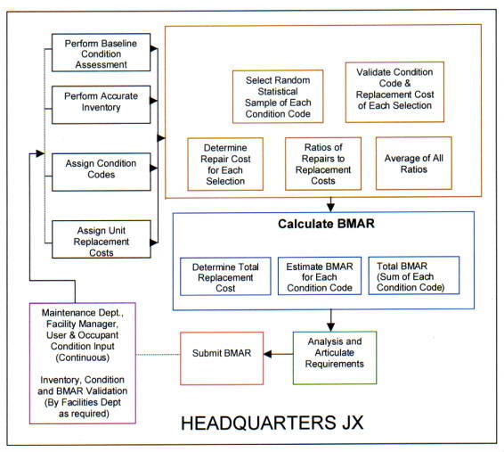
Step 3 - Assign a condition code to all plant facilities and equipment. The condition assessment level code to be used should be simple, basic and easily understood. The condition codes proposed in Method 2 add excellent parameters that succinctly describe what the status of the item is and the scope of work required to bring it to acceptable maintenance standards. Much of this information can be provided from input by maintenance technicians, facility managers, users and occupants. It is important that it is simple, but with sufficient definition that everyone can at least attempt to apply it in a similar manner. Most NASA Centers either already have condition codes established, or are in the process of establishing them. Most condition data is or will be contained in facility condition assessment (FCA) databases, and some are in both the FCA and CMMS databases. It should not be a significant effort on the part of the NASA Centers and Component facilities to complete this action, and most are already in the process of completing it.
Step 4 - Assign Replacement costs. Current replacement costs for all inventory items must be established in the database to be used. Some NASA locations already have this information in their FCA or CMMS database. It is important that this data be developed from reputable cost reference data/guides. Most locations already use some form of the R S Means Maintenance and Repair Cost Data. It is recommended that the database that contains replacement cost data be set up to automatically update the costs to accommodate inflation. This action will be required at most NASA locations, but should not be too resource intensive to accomplish.
Step 5 - Calculate the Condition Code Factor. Calculation of the Condition Code Factor (CCF) will be peculiar to each Center depending on the condition of its facilities and equipment.
(1) Randomly select a statistically appropriate sample size (based on the confidence level desired) of inventory items for each condition code. An electronic or manual statistical sample selection table may be used to determine the appropriate and statistically accurate sample size. Websites are available on the internet where the required and statistically accurate sample size will be calculated at no cost by inputting basic information such as total population and desired degree of accuracy. On the web, search for statistical sample size and several on-line calculating services (and software sales companies) will be identified.
(2) Determine the condition code and replacement cost for each of the items selected.
(3) Estimate the required repair costs for each of the inventory items selected in each condition code.
(4) Divide the required repair costs for each item selected by its corresponding replacement cost.
(5) Average the ratio of repair required to the current replacement cost for all items selected in each condition code. This is the CCF and there will be one for each condition code.
The most important part of this procedure is the true random selection of an appropriate sample size of inventory items within each condition code. This selection can be accomplished with the use of an electronic random number generator given that all the needed information is available in the database. Again, the randomness of inventory item selection and the determination of the proper sample size is key to the standardization and accuracy of the process. The determination of the appropriate sample size should be based on the level of confidence desired for the resultant BMAR approximation. The application of this calculation throughout NASA will not require a significant effort once the appropriate information is available in a database.
Step 6 - Calculate the BMAR approximation.
(1) Determine the total replacement cost for all inventory items included in each condition code.
(2) Multiply the CCF for each condition code by the total replacement cost of all inventory items included in each condition code. This is the estimated BMAR for each condition code.
(3) Sum the estimates of BMAR for each condition code. This is the statistically estimated BMAR for the entire physical plant for that location.
Step 7 - Use key management information for articulating requirements and analysis. If the BMAR calculation is accomplished from the CMMS database, additional information (criticality codes, failure data and historical cost and trouble call data) will also be available to further define and analyze the resultant BMAR calculation. Even if the calculation is done in another database, some of this analysis can be done manually, if necessary. Very few NASA locations have included their condition assessment information in their CMMS or linked the two databases. However, at most NASA locations, both databases are compatible and could be linked in the future if resources are available and it was deemed a cost-effective initiative.
Step 8 - Periodically validate condition codes. If the condition codes are periodically verified, especially as part of an already regularly scheduled maintenance inspection (PM/PT&I) or through input from the facility managers, building occupants or equipment users, the BMAR calculation almost becomes a real time estimate and follow-on (after the baseline) condition assessments are not required. This is done at some NASA locations currently. This procedure definitely depends on the size of the inventory and the ability to incorporate the condition code review without expending excessive resources. This procedure would not only determine a more accurate calculation, but could provide additional requirements information for the development of long-range plans. The more current the condition code, the better the assessment of current and future needs, and the more credible the calculation becomes. This is especially recommended for locations with small or medium size plant inventories.
Step 9 - Limit the inventory if it is cost-effective. A modification to this procedure to further reduce costs should be considered. Instead of including all inventory items in the calculation, it could be limited to the major facilities and their equipment, and the results extrapolated to determine the BMAR for the remaining assets. This would certainly make the process simpler for the larger locations with large plant inventories. This modification should be considered and possibly tested at all locations and applied where it will be cost-effective.
Method 2 - This methodology is described in Deferred Maintenance/Condition Assessment Discussion Paper, developed by Charles B. Pittinger, Jr., Facilities Engineering Division, Headquarters National Aeronautics and Space Administration (NASA), for presentation to the National Research Council.
This process of documenting deferred maintenance is designed to be a simplified approach based on creative thinking, which is minimally resource intensive and auditable in order to support Federal agencies annual financial reports. Its intended use is as a facility performance metric, which can be compared and trended against other commonly used facility metrics. It is a parametric estimate intended to be accurate enough for its intended purpose - a MACRO level metric.
The method assumes condition assessments are performed at the system level rather than the component level, simple condition levels are used, there are a limited number of systems to assess, and parametric estimating is used based on the CRV of the systems and the facility they support.
A simple 5-tiered condition code system is proposed which is assigned a representative repair cost factor based on a percentage of the facility CRV. The range of CRV by condition level is subject to further study.
| Condition Assessment Level | Repair Cost |
| 5 - New/Only PM required | 5% of CRV |
| 4 - Some repairs needed, system generally functional | 20% of CRV |
| 3 - Many repairs needed, limited functionality | 50% of CRV |
| 2 - May be functional, but obsolete or does not meet codes | 100% of CRV |
| 1 - Not operational, unsafe | 100% of CRV |
The major facility systems are identified and assigned representative cost factors based on their estimated percentage of the facility CRV. These factors can be adjusted for special facilities (wind tunnels, launch platforms, etc.). The range of CRV by major system is subject to further study.
| Major system | % of Facility CRV |
| Architectural | 5 |
| Roof | 10 |
| Electrical | 15 |
| Plumbing | 15 |
| HVAC | 25 |
| Structural | 30 |
| 100 | |
| Site | 100 |
| Utility Systems - exterior | 100 |
The procedure then determines the condition codes for the systems, site and utilities for a given facility, multiplies the appropriate repair cost factors and system cost factors for each and sums them for the facility (site and utilities separate). This total system factor is then multiplied by the facility CRV (same for site and utilities CRV's) and added to the site and utilities calculation to come up with an estimated value for the deferred maintenance for that facility.
The cost of gathering deferred maintenance data can be reduced further by inspecting a smaller group of facilities that represent the majority of an agency's CRV and then extrapolating for the remainder of the assets.
This procedure is based on the condition of the plant, and focuses on the system and facility level rather than the component level. It involves a simplified condition code system and parametric estimating to determine an approximation of a facility's BMAR.
Method 3 - This procedure was developed and suggested by Greg Spencer, Chief, Maintenance and Logistics Branch, Dryden Flight Research Center, during the NASA Facilities Maintenance Workshop, February 2000.
This is a condition-based method, which is a simplified version of Method 1. It is a statistical model, which uses real property data (CRV) and is based at the facility level rather than at the equipment level. A facility is divided into three major systems, which are assigned weighted percentages representing their expected impact on overall facility condition, e.g., structural - 40%, mechanical - 30%, and electrical - 30%. The process involves randomly selecting the proper sample size of facilities (based on confidence level desired) and determining each facility's overall net condition. This is done by summing the product of each system's condition code (using standard NASA 5-tiered condition codes) and its weighted percentage. An example for a single facility could be:
| System | Condition Code | System Weight |
| Structural | 3 | 40% |
| Mechanical | 3 | 30% |
| Electrical | 4 | 30% |
Facility Net Condition Code = (3 x 0.4)+(3 x 0.3)+(4 x 0.3) = 3.3
A Condition Code Factor (CCF) is then determined for each facility. Based on actual data from DFRC, the CCF can be represented by an exponentially decaying function (the CCF approaches zero (exponentially) as the facility net condition code increases from one to five (as shown in Figure 1 below).
This relationship between the CCF and the Net Facility Condition is a reasonable expectation at most locations and could be used as a standard assumption in using this method to approximate the BMAR. The CCF can then be calculated using the formula:
CCF = k1(exp(k2( 1 - NC))) where:
CCF = condition code factor
k1 and k2 = constants (value of constants is subject to further study)
exp = "e" or 2.718
NC = the net condition code for the facility
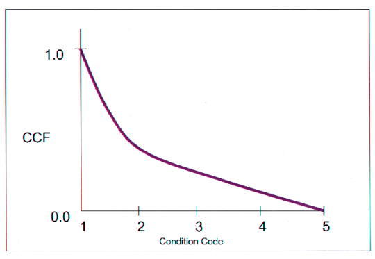
The approximation of the BMAR for the facility involved is then determined by multiplying the CCF by the CRV for the facility. The BMAR for the overall site is determined by averaging the CCF for all facilities selected in the random sample, and multiplying that average CCF by the total CRV for the site.
This process is strictly condition based and is a simplified statistical calculation where lessor degrees of accuracy are acceptable.
Table of Contents
| 1. | Introduction............................................................................................................................................ | I-2 |
| 2. | Organizational Structure for Award Term Administration .............................................................. | I-2 |
| 3. | Evaluation Requirements .................................................................................................................... | I-3 |
| 4. | Method for Determining the Award Term ......................................................................................... | I-3 |
| 5. | Changes in Plan Coverage .................................................................................................................. | I-3 |
| Attachments | ||
| A. | Performance Evaluation Factors ........................................................................................................ | I-4 |
| B. | Performance Evaluation Criteria ........................................................................................................ | I-5 |
1.1 In accordance with Clause H-10, Award Term, the contractor can earn additional performance periods through optimum contract performance. This Award Term Evaluation Plan describes the process the Government will utilize to evaluate performance and administer the contract's award term provisions.
1.2 The objective of the Award Term provisions is to incentivize the contractor to perform at an optimum manner by offering the opportunity to earn additional contract performance periods. If the contractor successfully incorporates this into daily operations, the Government will receive improved services at a reasonable cost and the contractor will receive additional contract performance periods.
1.3 The Government will formally evaluate the contractor's performance every six-months against the criteria established in the Award Term Evaluation Plan. The Government will provide the contractor with an informal mid-point (3-month) performance evaluation during each evaluation period. At the mid-point review, the Government will provide the contractor with written performance information that, as a minimum, details performance weaknesses identified during the period.
1.4 At the conclusion of each 6-month evaluation period, the Performance Evaluation Committee (PEC) will formally evaluate the contractor's overall performance against the performance evaluation criteria defined in this Plan. The PEC will recommend to the Award Term Determination Official (ATDO) a performance rating, commensurate with overall performance. The ATDO will consider the input provide by the PEC and make the performance rating in accordance with this Plan.
1.5 The Government will average the performance ratings for two consecutive 6-month periods for any Award Term decisions. The first contract year will be evaluated but no award term determination will be made. This will allow both the contractor and the Government to acclimate to the new contract. Except for contract year one, an award term decision will be made annually utilizing two consecutive six-month performance ratings. A rating of "Very Good" or better is needed to earn contract years 4 and 5. A rating of "Excellent" is needed to earn contract years 6 through 10.
1.6 3 The results of award term determinations are subject to the Disputes Clause.
The Performance Evaluation Committee (PEC) evaluates the contractor's overall performance for each evaluation period and recommends a performance rating to the Award Term Determination Official (ATDO). The Committee is comprised of the Chief of the Procurement Division and the Chief of the Plum Brook Management Office. The PEC is chaired by the Director of Engineering and Technical Services who shall serve as the Award Term Determination Official.
3Code G, General Counsel, September 7, 2000.
The ATDO will determine the contractor's six-month performance rating and the annual Award Term decision. The ATDO will transmit the "Notice of Performance Rating" letter to the contractor.
The Plum Brook Management Office and the Contracting Officer will provide performance evaluation information to the Performance Evaluation Committee.
Four factors will be used to evaluate the contractor's performance: technical performance, safety, quality, and cost and schedule management. Details are provided in Attachment A. The performance evaluation criteria are provided in Attachment B.
4.1 Within 15 days after the completion of the evaluation period, the Plum Brook Management Office and the Contracting Officer will summarize the contractor's performance and provide a "Performance Letter" to the contractor.
4.2 Within 5 days after receipt of the "Performance Letter", the contractor may provide a response that includes a contractor self-assessment.
4.3 Within 30 days after the completion of an evaluation period, the PEC will convene to review the contractor's overall performance during the period. Consideration shall be given to the information presented by the Plum Brook Management Office and the contractor's response to the "Performance Letter". If this is a 6-month interim review, the PEC recommends a performance rating to the ATDO. If this is a 12-month final review, the PEC recommends a 6-month performance rating and a 12-month average rating to the ATDO.
4.4 Within 3 days after the PEC review and award term determination meeting, the ATDO will prepare a "Notice of Performance Rating " letter for transmittal to the contractor.
The Government may unilaterally change the evaluation criteria of this Performance Evaluation Plan by providing the contractor written notification 30 calendar days prior to the commencement of an evaluation period.
Factor No. 1: Technical Performance Weight 25%
Description:
This factor evaluates the contractor's ability to effectively manage the technical aspects of this contract. It will be evaluated via internal and external customer surveys that will cover the evaluation criteria listed below.
Evaluation Criteria:
Factor No. 2: Safety Weight 25%
Description:
This factor evaluates the contractor's participation in OSHA's Voluntary Protection Program (VPP).
Evaluation Criteria:
Factor No. 3: Quality Weight 25%
Description:
This factor evaluates the contractor's assistance with maintaining Plum Brook's ISO 9001 registration.
Evaluation Criteria:
Factor No. 4: Cost and Schedule Management Weight 25%
Description:
This factor evaluates the contractor's ability to effectively manage the cost and schedule processes to produce a work product that is "within budget" and "on time". It will be evaluated via internal and external customer surveys that will cover the evaluation criteria listed below.
Evaluation Criteria:
| Category | Excellent | Very Good | Good | Satisfactory | Unsatisfactory |
| Points Available | 91 to 100 | 81 to 90 | 71 to 80 | 61 to 70 | Less than 61 |
| Technical Performance(25%) | Averaged customer survey rating is > 9. | Averaged customer survey rating is 8. | Averaged customer survey rating is 6 < x < 8. |
Averaged customer survey rating is 5 < x < 6. | Averaged customer survey rating is < 5. |
| Safety(25%) | Obtain or maintain VPP Star certification. At least 95% average score on internal safety inspections/audits. | Obtain or maintain VPP Star certification. At least 90% average score on internal safety inspections/audits. | Obtain or maintain VPP Merit certification. At least 85% average score on internal safety inspections/audits. | Loss of VPP certification. At least 80% average score on internal safety inspections/audits. | Loss of VPP certification. Less than 80% average score on internal safety inspections/audits. |
| Quality(25%) | Pass internal audits with no more than 5 nonconformances. Pass surveillance audit. | Pass internal audits with no more than 10 nonconformances. Pass surveillance audit. | Pass internal audits with no more than 15 nonconformances. Pass surveillance audit. | Pass internal audits with more than 15 nonconformances. Pass surveillance audit. | Loss of ISO 9001 registration. |
| Cost and Schedule Management(25%) | Averaged customer survey rating is > 9. | Averaged customer survey rating is 8. | Averaged customer survey rating is 6 < x < 8. | Averaged customer survey rating is 5 < x < 6. | Averaged customer survey rating is < 5. |
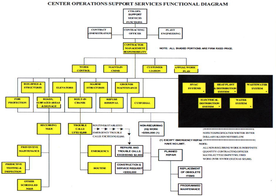 |
|
|
|
|
|
|
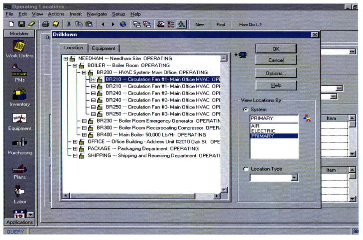 |
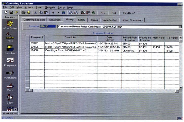 |
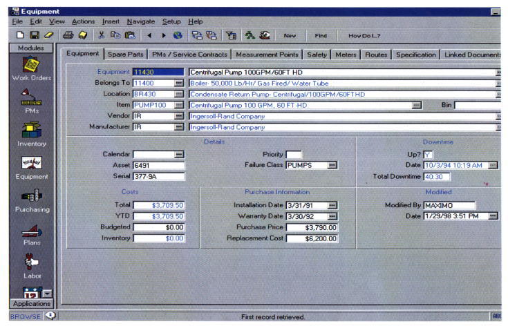 |
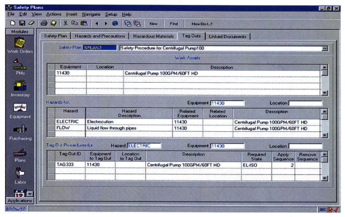 |
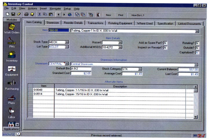 |
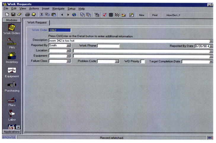 |
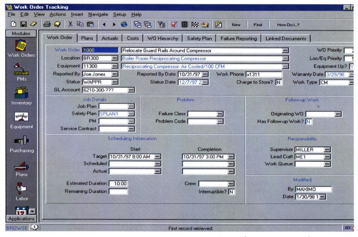 |
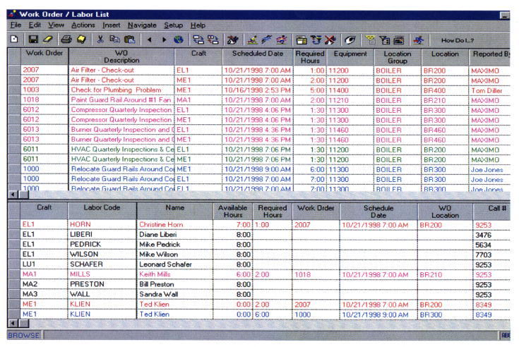 |
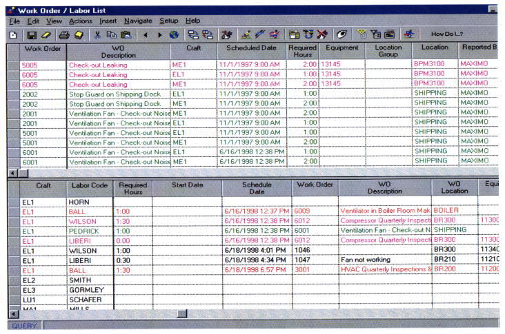 |
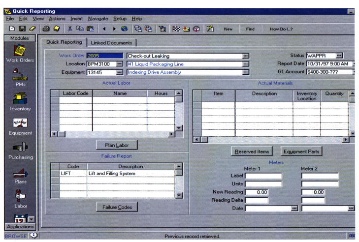 |
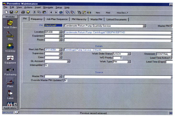 |
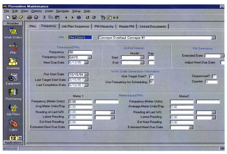 |
