APPENDIX D. CMMS Sample Screens
1. Introduction
This appendix includes sample computer screens for
various facilities maintenance functions that may be included in a Center's
CMMS. These samples are from a commercially available system and are
presented as a sample of some of the types of data handling capability
available.
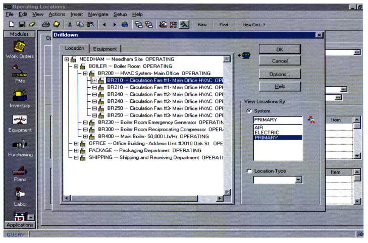
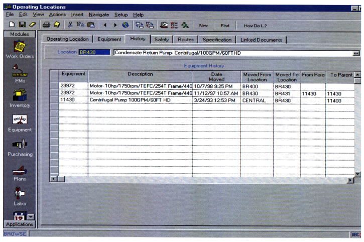
2. Operating Locations
The sample screens in Figures D-1 and D-2 are from
an Operating Location application that allows the operator to enter and
track locations of equipment and organize these locations into logical
hierarchies or network systems. Operating locations are the locations in
which equipment operates. Work orders can then be written either against
the location itself or against the equipment in the operating location.
Using locations allows for the tracking of the equipment's life-cycles
(history) and provides the capability to track equipment's performance at
specific sites.
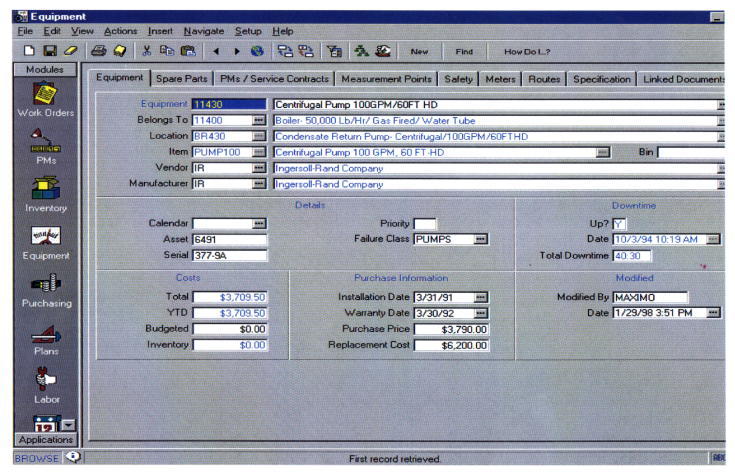
3. Equipment
Figure D-3 is a sample screen from an equipment
module that allows the operator to keep accurate and detailed records of
each piece of equipment. Accurate historical data can be used to help make
cost effective replace or repair decisions. All equipment related data is
available, such as bill of material, preventive maintenance schedule,
service contracts, safety procedures, measurement points, multiple meters,
inspection routes, specification data (name plate), equipment downtime, and
related documents. This equipment data is used for managing day-to-day
operations. The data can be used to develop additional management
information, such as building equipment downtime failure code hierarchies
to use in maintenance management metrics.
Figure D-1. Sample Operating Locations Drilldown Screen
Figure D-2. Sample Operating Location Equipment History
Figure D-3. Sample Equipment Screen
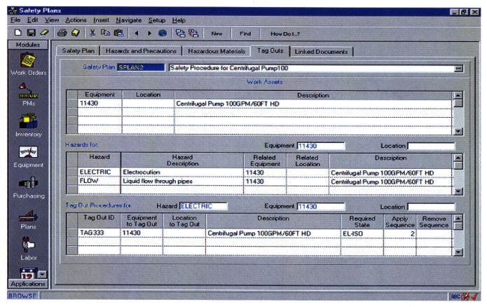
4. Safety Plans
Figure D-4 shows the tag out screen of the safety
plan module of this example system. With the emphasis placed of safety in
NASA this module or similar capability is an important addition to the
CMMS. This sample module provides the following capabilities:
a. Manual or automatic safety plan numbering.
b. Safety plans can be built ad-hoc for special work
or defined for re-use in the Safety Plans application.
c. Track hazards for multiple equipment and
locations.
d. Multiple precautions can be associated to a
hazard.
e. Track hazardous materials for multiple equipment
and locations.
f. Once hazards and precautions are entered,
convenient pop-up list in this sample system is available for reference and
data entry.
g. Track ratings for health, flammability, reactively,
contact, and MSDS for hazardous materials.
h. Define lock-out/tag-out procedures.
i. Define tag identifications for specific equipment
and locations.
j. Define safety plans for multiple equipment or
locations.
k. View link documents.
l. Associate safety plans to job plans, to
preventative maintenance masters and to work orders.
m. Safety plans are printed automatically on work
orders.
n. Flexible business rules allows tag outs procedures
to be associated to hazards OR directly to locations, equipment, safety
plans or work orders.
o. Copy existing safety plans to new safety plans.
Figure D-4. Sample Safety Plans Screen
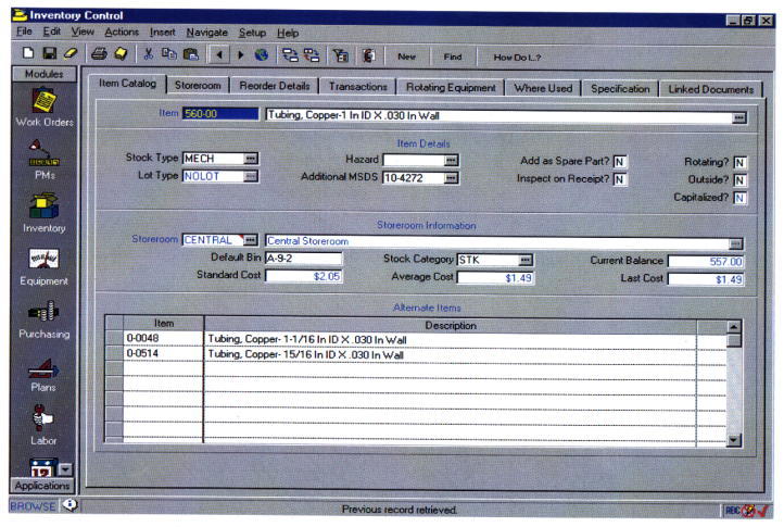
5. Inventory Control
The Inventory Control application shown in Figures
D-5 allows the operator to track inventory movement such as move items in
or out of inventory, or from one location to another. Stocked, nonstocked,
and special order items can be tracked. The application as shown in Figure
D-5 also allows the tracking of item vendors, the locations where an item
can be found, item cost information, and the substitute or alternate items
that can be used if necessary.
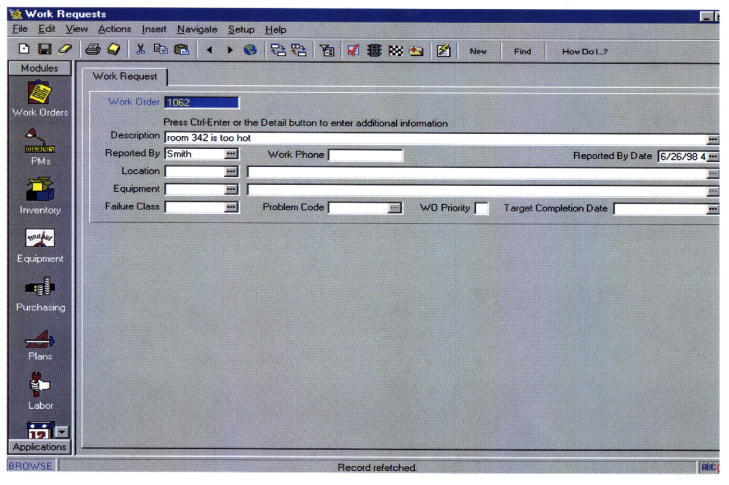
6. Work Request
Figure D-6 is a sample work request screen that could
be used by anyone at a Center to input-request, such as trouble calls, or
by work control to record-request. The simple to use data entry screen was
designed for minimal data entry. The work order number is assigned
manually or automatically. A requester would enter minimal data, as shown
on the sample, with work control entering additional information as
required. Data is entered once, and pop-up tables in this system eliminate
the need to memorize codes. This computer system could be used by a Center
in their CMMS rather than the Trouble Call Ticket shown in Appendix C.
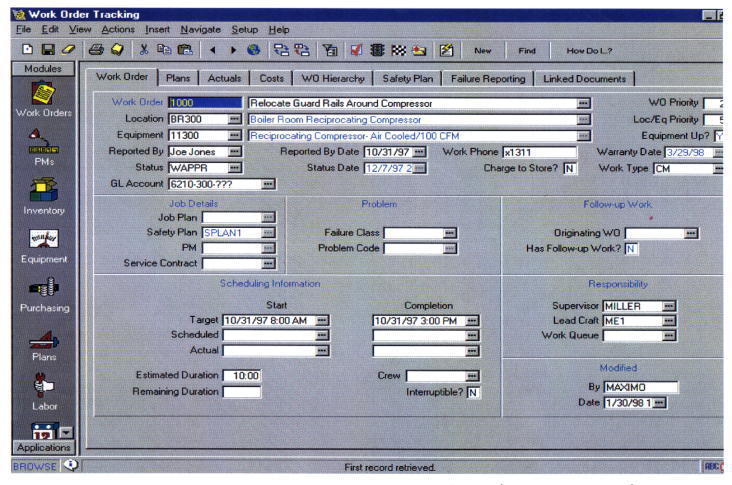
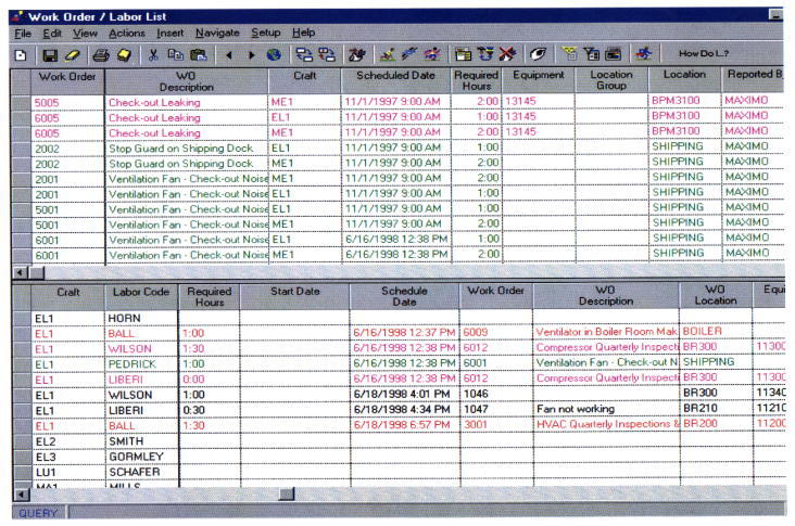
7. Work Order Tracking
The Sample Work Order Tracking Screen shown in Figure
D-7 is the heart of a work order system. The data is entered once, and
pop-up tables eliminate the need to memorize codes. This tracking system
provides instant access to all of the information needed for detailed
planning and scheduling, including work plan operations, labor, materials,
tools, costs, equipment, blueprints, related documents, and failure
analysis. Of course, this is dependent on how many modules have been
installed and how much information has been entered in the system.
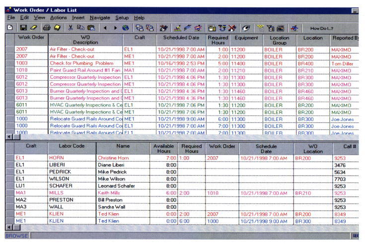
8. Work Management
a. The Work Manager module in this example system
lets the planner specify which labor to apply to specific work orders and
when. It has two modes, Dispatching and Planning.
b. In the Planning Mode shown in Figure D-8, labor
assignments are planned for future shifts. Each person's calendar
availability is considered when the assignments are made. The assignments
are created sequentially over the shift, filling each person's daily
schedule with priority work for the craft. It can even split larger jobs
over multiple shifts - automatically.
c. In the Dispatch Mode shown in Figure D-9 labor
assignments are carried out as soon as possible. This system in this
example can even begin tracking labor time from the instant the assignment
is made. The system operator can interrupt work already in progress in
order to reassign labor resources to more crucial work.
Figure D-5. Sample Inventory Control Screen
Figure D-6. Sample Work Request Screen
Figure D-7. Sample Work Order Tracking Screen
Figure D-8. Sample Planning Screen
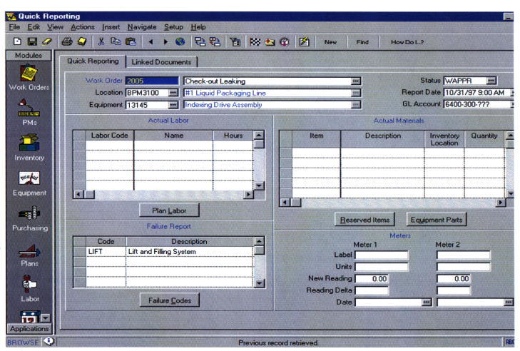
9. Quick Reporting
Figure D-10 shows a sample Quick Reporting screen
that provides a rapid and easy means for opening, reporting on, and closing
work orders, reporting work on small jobs after-the-fact, and even creating
work orders on-the-fly. Labor, materials, failure codes, completion date,
and downtime can all be reported on this one screen.
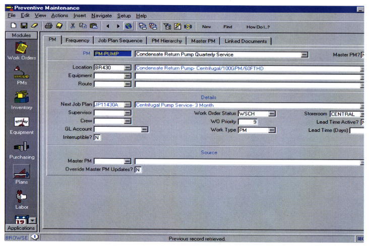
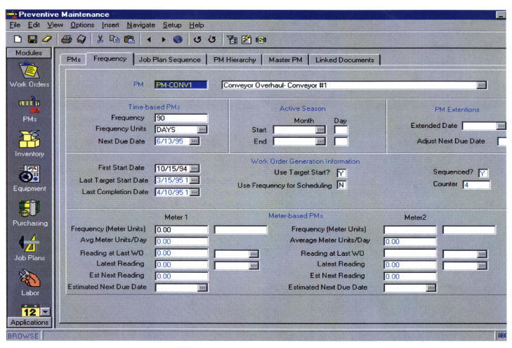
10. Preventive Maintenance
Sample preventive maintenance screens are shown in
Figures D-11 and 12. The following capabilities provided in this sample
system are listed to show how a CMMS can be utilized in managing a Center's
PM program:
a. Supports multiple criteria for generating PM work
orders. If a PM master has both time-based and meter-based frequency
information the program uses whichever comes due first, and then updates
the other.
b. Generates time-based PM work orders based upon
last generation or last completion date. Next due date and job plans are
displayed.
c. Permits and tracks PM extensions with adjustments
to next due date.
d. Triggers meter based PMs by two separate meters.
e. Prints sequence Job Plans when wanted.
f. Creates a PM against an item so new parts have
PMs automatically generated on purchase.
g. Specifies the number of days ahead to generate
work orders from PM Masters that may not yet have met their frequency
criteria.
h. Consolidates weekly, monthly, and quarterly job
plans on a single master.
i. Assigns sequence numbers to job plans to tell the
system which job plan to use when a PM work order is generated from a PM
Master.
j. Permits overriding frequency criteria in order to
generate PM work orders whenever plant conditions require.
k. Routes PMs with multiple equipment or locations.
l. Generates work orders in batch or individually for
only the equipment wanted.
m. Can be used with the system Scheduler to forecast
resources and budgets.
Figure D-9. Sample Dispatch Screen
Figure D-10. Sample Quick Reporting Screen
Figure D-11. Sample Preventive Maintenance Screen
Figure D-12. Sample Preventive Maintenance Frequency
Folder
DISTRIBUTION:
NODIS
This Document is Obsolete and Is No Longer Used.
Check the NODIS Library to access the current version:
http://nodis3.gsfc.nasa.gov
![[NASA Logo]](../Images/nasaball.gif)