CHAPTER 8. Reliability Centered Building and Equipment Acceptance
8.1. Introduction
a. During the course of new construction, major
repair, or rehabilitation of facilities, it is not unusual to discover
installed systems or equipment that are out of alignment and balance, that
contain latent defects from manufacturing and installation, or that simply
do not operate as intended. For example, evaluations of new construction
of at least two NASA Centers revealed that 85- to 100-percent of the
rotating equipment was misaligned, out-of-balance, or contained defective
bearings. These types of systems or equipment defects result in premature
failures, which require unbudgeted corrective action by O&M staff. Given
today's tight facilities O&M budgets, each Center should, for new
construction, major repair, or rehabilitation of facility projects, employ
an acceptance process that includes the use of PT&I to verify system and
equipment condition. This should be done prior to acceptance of the work
and the contractor's departure from the job site and turning the keys over
to the operations and maintenance staff. The expected end result is a
facility that is safer and is less costly to maintain. The acceptance
process can achieve these results by:
(1) Ensuring there are no latent factory or
installation defects;
(2) Verifying building systems and equipment
performance through functional performance testing; and
(3) Providing full documentation and training for the
O&M staff to improve their performance.
b. Building and equipment acceptance is one element
of a larger, more comprehensive construction quality program known as
"Commissioning". Currently, there are three variations of commissioning
being practiced - Traditional Commissioning, Total Building Commissioning
and NASA's customized application of a portion of Commissioning called
Reliability Centered Building and Equipment Acceptance.
8.1.1. Traditional Commissioning. Traditional
Commissioning involves performing random tests and checks on facility
systems to ensure that they are properly balanced, functionally operational
and comply with the design intent. It systematically checks operating
parameters such as pressure, temperature, minimum and maximum air flow,
lighting levels, electrical amperage and voltage, torque, fluid volumes,
and other thermodynamic measures at key locations, as well as balanced
conditions. It is a method of acceptance testing that, when performed on
a random basis at random sampling points, checks to ensure that the outcome
indices at those points are in compliance with the outcome requirements
stated in the design specification. Although the method ensures that the
installation meets the design requirements, Traditional Commissioning
reflects the conditions in a snapshot in time, specifically on the day(s)
that the system is being inspected for acceptance. Also, it generally
fails to emphasize the quality of the equipment installation itself, such
as latent manufacturing and installation defects. Even if the installation
is in compliance with the design and reflects the proper process parameters
at the time of equipment acceptance, these undetected defects may result in
premature equipment failure and operational and maintenance headaches due
to misalignment or similar condition discovered at a later date. The
problem then becomes one of many warranty issues, which based on past,
typical NASA history, often are inadequately enforced.
8.1.2. Total Building Commissioning. Total Building
Commissioning is a cradle-to-grave systematic process of ensuring that
facility systems are planned, designed, installed, tested, and capable of
being operated and maintained to perform according to the design intent and
the user's needs. The Total Commissioning process is optimally applied to
all phases of a construction project - program planning, design,
construction/installation, acceptance and postacceptance/ occupancy.
Commissioning team involvement begins at the earliest stages of project
planning, where its expertise in such areas as system sizing, code
compliance, maintainability, user friendliness, product quality and
reliability, ergonomics and projected life-cycle costs, is applied to the
design. The commissioning staff is also involved in monitoring the quality
of the construction in terms of workmanship and specification and code
compliance throughout the construction, using Traditional Commissioning
tests and inspection procedures for quality assurance and for system
acceptance. Finally, the quality team monitors the installed system
following acceptance to ensure that there are no latent installation
defects or degradation of system performance and operational quality. This
rigorous commissioning process is intended to provide the following
benefits:
a. Ensure that a new facility begins its life with
systems at optimal productivity.
b. Improve the likelihood that the facility will
maintain this level of performance.
c. Restore an existing facility to high productivity.
d. Ensure facility renovations and equipment upgrades
function as designed.
8.1.3. NASA's Building and Equipment Acceptance.
NASA's application of Commissioning is a customization of a portion of the
Traditional and Total Commissioning processes that NASA calls Reliability
Centered Building and Equipment Acceptance. NASA recognizes there can be
substantial benefit even when commissioning concepts are applied only to
the acceptance phase of a construction project. These benefits can be
gained during acceptance by using available PT&I technologies in addition
to traditional operational parameters to identify latent manufacturing,
shipping, and installation induced defects. Identifying and correcting
these defects can reduce premature failures, increase safety and
reliability and decrease life-cycle costs. NASA's portion of the
Commissioning concept concentrates on facility and equipment acceptance
rather than on Total Commissioning's cradle to grave detailed oversight and
evaluations because of the following:
a. NASA's placing safety as a top priority.
b. The current Federal budget process involving
project funding from numerous autonomous and nonintegratable sources
c. NASA's emphasis on reducing life-cycle costs within
available and limited resources.
d. The institution of a strong and vibrant RCM program
in place Agencywide.
8.1.4. Many of the problems, safety concerns and
associated costs inherited during the O&M phase are the result of i
nadequate or nonexistent standards and procedures for equipment acceptance.
Thus, the focus of NASA's equipment acceptance is on ensuring that the
contractor detects latent manufacturing and installation defects through
an effective quality control program before final acceptance of the
installation by the Government.
8.1.5. This chapter provides a brief overview of
NASA's Acceptance program. Refer to the NASA Reliability Centered
Building and Equipment Acceptance Guide for more detailed information and
extensive discussion of the subject.
8.2. RCM - Integral to Acceptance
The RCM approach takes a life-cycle view of
facilities and collateral equipment and seeks to ensure that facilities and
collateral equipment are properly built and installed in order to reduce
the probability of premature failure. A key element in the transition from
good design to full operation is the construction and acceptance phase.
8.2.1. Initial Planning and Design. The long-term
reliability of an installation or refurbishment begins with the initial
planning and design. The initial criteria and equipment design determines
the inherent equipment reliability, maintainability, and supportability.
Moreover, as discussed in Chapter 7, Reliability Centered Maintenance,
about 95 percent of the total equipment cost is determined by the end of
the planning and design phase. Even though expenditures for plant and
equipment may occur later during the acquisition process, their cost is
committed at an early stage. The decision to include a facility in the
RCM program, including PT&I, is best made during the planning phase. As
RCM decisions are made later in the life cycle, it becomes more difficult
to achieve the maximum possible benefit from the RCM program. It has been
estimated by NASA facilities and collateral equipment designers that the
cost to make a system change, once the system is built, is anywhere from 10
to 1,000 times more than if the change was incorporated during the system
design. Clearly, the planning and design phase of facilities and
collateral equipment life cycle is the time to focus on the ability to
sustain operation through the use of effective acceptance testing, proper
trending, necessary maintenance, and the performance of timely repair, when
needed.
8.2.2. Construction and Acceptance. Contracts for
construction work at NASA Centers shall require contractor responsibility
for an adequate quality control program in place for the proper
installation of the facility and equipment in accordance with the design
requirements. Throughout the installation and at the time of acceptance,
PT&I must be performed to verify that not only is the installation
acceptable, i.e., that there are no latent factory or installation defects,
but also that the required baselines are established. Consequently, any
contractor performing work at NASA centers must have an understanding of
the RCM process and how it affects the project. NASA contracts shall
require the contractor to use personnel who are trained and certified in
the appropriate PT&I technologies for acceptance testing to ensure that
the results are accurate and consistent. The Center's Construction
Manager is responsible for ensuring that all interim testing is performed
and that the results meet the specifications and are documented and
included with the final acceptance documentation. It is the Construction
Manager's responsibility to ensure that the acceptance testing has been
performed and to determine if the acceptance testing results are within
the required tolerances. When all acceptance criteria have been met, the
final responsibility of the Construction Manager is to collect all of the
required documentation, including all manufacturers manuals, drawing
redlines, and all acceptance testing data, and deliver it to the
appropriate Center operations and maintenance personnel.
8.2.3. Maintenance and Operations. Even though
maintenance is a relatively small portion of the overall life-cycle cost,
3 to 5 percent of a facility's operating cost, RCM is still capable of
introducing significant savings during the Maintenance and Operations phase
of a facility's life. Savings of 30 to 50 percent in the annual
maintenance budget are often obtained through the introduction of a
balanced RCM program. O&M personnel are ultimately responsible for the
proper operation and maintenance of systems and equipment. However, how
the facility and its equipment will be operated and maintained must be
considered during the planning, design, and construction phases. During
these phases, maintenance and operations needs are best served by carefully
and realistically identifying and defining the PT&I and PM requirements.
Although the performance of maintenance and operations occurs during the
operations stage of the life cycle, some preparatory activities can be
carried out during the acceptance stage. These activities can include O&M
personnel selection, training requirements, procedure preparation, review
of specifications, and the collection of baseline condition monitoring data
from the Construction Manager. Refer to Chapter 7, Reliability Centered
Maintenance, of this document and to the NASA Reliability Centered
Maintenance Guide for Facilities and Collateral Equipment for guidance on
the use of RCM during facilities operations and maintenance.
8.3. Acceptance Testing
8.3.1. After construction is complete, it is
important to verify that the systems and equipment are operating in
accordance with the construction specifications. NASA's contracts shall
accomplish this by requiring the contractor to verify, as an element of
the contractor's quality control program, that the equipment specified is
properly installed in accordance with design and local codes and standards,
that there are no latent manufacturing or installation defects, and that
individual and integrated systems and equipment operation is in accordance
with the design intent. During NASA's acceptance process, individual
equipment is acceptance-tested using PT&I, that focuses on equipment
performance, and by traditional thermodynamic testing. By providing this
initial baseline data for comparisons and trending it allows for the
planning and scheduling of PM or repairs in advance of failure.
8.3.2. Facilities contain a myriad of equipment and
systems, from the simplest light switch to a computer-controlled air
conditioning system. While, all equipment can benefit from the reliability
centered acceptance process it must be understood that even though an
acceptance test is available, it is not always cost effective to perform.
The decision to perform reliability centered acceptance should be based on
the RCM techniques in the NASA RCM Guide for Facilities and Collateral
Equipment and the NASA Reliability Centered Building and Equipment
reliability centered Acceptance Guide.
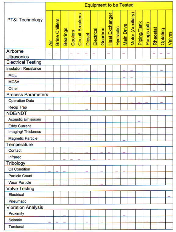
8.3.3. Table 8-1 indicates the most appropriate and
commonly used PT&I technologies with respect to the most common acceptance
testing applications. These PT&I tests have become some of the most
effective methods for testing new and in-service equipment for hidden
defects.
8.3.4. Preliminary and final acceptance testing and
documentation of the test results is to be performed by the contractor as
part of the contractor's Quality Control program. The contractor must
correct all detected deficiencies, and the condition monitoring data shall
be retaken prior to acceptance of the facility and/or equipment by NASA.
The NASA Center must observe and monitor this condition testing, analysis
and documentation as part of its Quality Assurance program and ensure that
the contractor provides all preliminary and final condition monitoring and
analysis data to the Construction Manager.
8.4. Acceptance Scope
The acceptance scope includes but is not limited to
the following:
a. Documenting the design intent. Verifying that
equipment and systems have been properly installed in accordance with the
contract documentation and the manufacturer's written installation
instructions.
b. Verifying the performance of each piece of
equipment and each system, documenting the equipment and system performance
and ensuring that there are no latent manufacturing and installation
defects.
c. Verifying that equipment has been placed into
operation with the manufacturer's observation and/or approval.
d. Verifying that adjusting, balancing and system
testing has been properly performed.
e. Assembling and submitting record drawings
Table 8-1. Applicable PT&I Technologies
f. Training Center and/or the User's personnel in the
proper operation of each piece of equipment and each system.
g. Documenting warranty start and end dates.
h. Assembling and submitting all records of Code
authority inspections and approvals.
i. Validating the accessibility of all work relative
to the maintenance requirements of each piece of equipment and promptly
advising NASA of items of noncompliance.
j. Identifying, documenting and reporting all
deficiencies of the work relative to the contract documents for tracking
and correction through a deficiency-tracking program.
8.5. Applications
8.5.1. Roofs. Roofs are normally constructed layer
by layer and comprised of many different types of materials. Moisture must
not be allowed to enter the roof structure or materials during the
construction phase, as any trapped moisture will eventually degrade the
roof and structure and can cause a premature failure of the roofing system.
Whereas traditional roof inspections usually look for the effects of leaks,
infrared thermography should be used to look for wet insulation caused by
water ingress during construction, improper installation or roof boundary
failures.
8.5.2. Insulation/Building Envelope. Building
insulation is installed during construction but in most cases, prior to the
building being completed. Consequently, acceptance inspections must occur
before the walls and ceilings are completed. On completion of the
insulation installation a construction detail showing the insulation
material type, amount, and location must be generated and submitted by the
contractor. This information shall be forwarded to the appropriate RCM
official for inclusion in the maintenance database. Infrared Thermography
or ultrasonic mapping should be used during acceptance to identify
insulation voids, insulation settling, and areas of moisture intrusion.
8.5.3. Piping Systems. Industry standard acceptance
tests for water, plumbing and air systems first require a pressure test of
all piping and fittings. During this test an ultrasonic scan should be
performed on all accessible aboveground piping to help discover any leaks.
For hot water systems, after the pressure and hydro tests are completed,
and after piping insulation has been installed, the system should be
charged with hot water and an infrared scan be performed to verify
insulation integrity. For steam systems, ultrasonic scans should be
performed on steam traps.
8.5.4. Mechanical Systems
8.5.4.1. Vibration Analysis. Analysis of system and
equipment vibration levels is one of the most commonly used PT&I techniques
to determine the condition of the rotating equipment and its structural
stability in a system. It will detect deficiencies associated with wear,
imbalance, misalignment, mechanical looseness, bearing damage, belt flaws,
sheave and pulley flaws, gear damage, flow turbulence, cavitation,
structural resonance and fatigue. Vibration measurements in the acceptance
process must be performed by technically qualified persons, trained,
experienced and certified in vibration measurement and be taken under
specified operating conditions. Test documentation, including machine
layout drawings indicating vibration measurement locations, must be
submitted and validated and signed by the NASA construction manager or
other authorized official prior to final equipment acceptance.
8.5.4.2. Balance. Only 10- to 20-percent of rolling
element bearings achieve their design life. Premature bearing failure is
frequently caused by excessive vibration caused by imbalance and
misalignment. Acceptance testing for precision balance by the contractor
at the time of equipment acceptance of motor rotors, pump impellers and
fans is one of the most critical and cost effective techniques for
achieving increased bearing life and resultant equipment reliability.
NASA contracts shall require that balance measurements be performed by a
technically qualified person trained, experienced and certified in
machinery balancing.
8.5.4.3. Alignment. The forces of vibration from
misalignment cause gradual deterioration of seals, couplings, bearings,
drive windings and other rotating elements where close tolerances exist.
The use of precision equipment and methods, such as reverse dial and laser
systems to bring alignment tolerances within precision standards, by the
contractor at the time of acceptance is necessary. Precision alignment
will increase the average bearing life, decrease maintenance costs, and
increase machinery availability.
8.5.4.4. Lubrication and Hydraulic Fluids.
Lubricating and hydraulic fluid analysis is performed during acceptance for
three reasons: to determine the machine mechanical wear condition; to
determine the fluid condition; and to determine if the fluid has become
contaminated. There is a wide variety of tests to provide information on
these, usually packaged by independent testing laboratories to address all
three areas. In addition to assessing the condition of the fluids at the
time of equipment acceptance, these tests are necessary to provide a
baseline for future RCM actions.
8.5.4.5. Ultrasonic Testing. Airborne ultrasonics
is used by the contractor during equipment acceptance to hear noises
associated with leaks, corona discharges, and other high frequency events.
In addition to evaluating heat exchangers, ultrasonics can be used to
verify boiler casing and associated piping integrity and the proper
operation of steam traps.
8.5.4.6. Infrared Imaging. See paragraph 8.5.5.1,
Infrared Imaging.
8.5.5. Electrical Systems
8.5.5.1. Infrared Imaging. Infrared Thermography
(IRT) is a noncontact technique used during acceptance to identify hot and
cold spots in energized electrical equipment, large surface areas such as
boilers and building walls, and other areas where "stand off" temperature
measurements is necessary. More specifically, IRT is used to detect
faulty conditions in transformers, motor control centers, switchgear,
substations, switchyards and power lines. In mechanical systems, IRT is
used to identify blocked flow conditions in heat exchangers, condensers,
transformer-cooling radiators and pipes and to verify fluid levels in large
containers such as fuel storage tanks. Paragraphs 8.5.1. through 8.5.3.
discuss IRT's applications specific to structural systems.
8.5.5.2. Power Factor Testing. Providing the
optimum power factor maximizes the efficient use of electrical power.
Power Factor, sometimes referred to as dissipation factor, is the measure
of the power loss through the insulation system to ground. It is a
dimensionless ratio that is expressed in percent of the resistive current
flowing through an insulation to the total current flowing. Consequently,
the power factor test is used for making routine comparisons of the
condition of an insulation system and for acceptance testing to verify the
equipment was manufactured and installed properly. The test is
nondestructive, and regular maintenance testing will not deteriorate or
damage insulation. Its most frequent applications are with electric motors,
circuit breakers, motor control centers, switchgear, and transformers.
8.5.5.3. Insulation Resistance Testing. An
insulation resistance test is a nondestructive Direct Current (DC) test
used during acceptance to determine the condition of the of insulation of
electrical systems. It indicates that the insulation under test can
withstand the voltage being applied. The insulation resistance is
generally accepted as a reliable indication of the presence of
contamination or degradation. Its most frequent applications are with
motors, switchgear, motor control centers, circuit breakers and
transformers.
8.5.5.4. Insulation Oil Testing. High and medium
voltage transformers, some high and medium voltage breakers, and some
medium voltage switches are supplied with mineral oil as an insulation
medium. Performing oil tests prior to turnover is needed to ensure that
proper oil is installed and that the necessary inhibitors have been added.
Further, when insulation systems are subjected to stresses, such as fault
currents and overheating, combustible gas generation can change
dramatically. In most cases these stresses can be detected early on; the
presence and quantity of the individual gases can be measured and the
results analyzed to indicate the probable cause of generation.
8.5.5.5. Motor Circuit Evaluation (MCE) and Motor
Circuit Analysis (MCA). MCE is used during acceptance to evaluate the
condition of motor power circuits. Any impedance imbalances in a motor
will result in a voltage imbalance. Voltage imbalances in turn will result
in higher operating current and temperatures, which will weaken the .
insulation and shorten the motor's life. MCA is a method of detecting the
presence of broken or cracked rotor bars or high resistance connections in
end rings. While MCA is an effective test on in-service motors it is not
generally used for acceptance testing. It is, however, normally performed
at initial startup so a baseline can be established.8.5.5.6. Battery Impedance Testing. As a battery
ages and begins to lose capacity, its internal impedance rises. This is a
parameter that can be trended, comparing the current value with the
original value, taken at acceptance, with previous readings, and with
other identical batteries in the same battery bank. Additionally, battery
impedance testing will indicate the existence of an internal short in the
battery, of an open circuit in the battery, and premature aging due to
excessive heat or discharges. There are no set guidelines and limits for
this test. Each type, style, and configuration of battery will have its
own impedance so it is important to take these measurements during
acceptance to establish a baseline.
8.5.5.7. Airborne Ultrasonics. Deficiencies in
electrical systems, such as corona discharges, loose switch connections,
and internal arcing in deadfront electrical connections can all be
discovered during acceptance using ultrasonic test devices. Corona
discharge is normally associated with high voltage distribution systems and
is produced as a result of a poor connection or insulation problem. The
discharges generally occur at random, are the precursor to a failure, and
are in the ultraviolet region and not normally detectable using
thermography.
8.6. Acceptance Data Sheet
Acceptance data is to be recorded on a formal
Acceptance Date Sheet and provided to the Center Construction Manager as
part of the facility or equipment documentation package. A separate sheet
must be filled out for each equipment unit being evaluated during the
acceptance process and may result in a voluminous total package. Refer to
the NASA Reliability Centered Building and Equipment Acceptance Guide for
Acceptance Date Sheet samples.
DISTRIBUTION:
NODIS
This Document is Obsolete and Is No Longer Used.
Check the NODIS Library to access the current version:
http://nodis3.gsfc.nasa.gov
![[NASA Logo]](../Images/nasaball.gif)