Procedural
Requirements
Effective Date: October 07, 2015
Expiration Date: October 06, 2025
|
|
NASA Procedural Requirements |
NPR 8831.2F Effective Date: October 07, 2015 Expiration Date: October 06, 2025 |
| | TOC | Change History | Preface | Chapter1 | Chapter2 | Chapter3 | Chapter4 | Chapter5 | Chapter6 | Chapter7 | Chapter8 | Chapter9 | Chapter10 | Chapter11 | Chapter12 | AppendixA | AppendixB | AppendixC | AppendixD | AppendixE | AppendixF | AppendixG | AppendixH | AppendixI | ALL | |
F.1 Descriptions of Predictive Testing Techniques This appendix provides brief descriptions of the most commonly used predictive testing techniques, reference sources, detailed data sheets on those techniques that are considered state of the art, and applications of miscellaneous inspection techniques. Refer to the NASA Reliability Centered Maintenance Guide for Facilities and Collateral Equipment for a more comprehensive and detailed discussion of PT&I.
F.1.1 Vibration Analysis
a. Frequency and Time Domain Measurement. Analyzes the spectra of frequencies to identify the main causes of rotating equipment mechanical problems (e.g., mechanical vibration, imbalance, and misalignment).
b. Shock Pulse. Evaluates the condition of bearings; measures the high-frequency noise generated when the moving elements in a bearing strike a defect and release mechanical energy.
c. Torsional Vibration Monitoring. Employs a pair of matched sensors to detect vibration of the equipment housing or structure caused by gear rotation and shaft torque.
F.1.2 Tribology and Lubricant Analysis (Condition Analysis)
a. Physical Analysis. Evaluates the color, appearance, and purity of a given oil, fuel, or grease sample to determine the presence of contaminants, breakdown of additives, corrosiveness, and viscosity.
b. Infrared Spectrography. Compares new oil and fuel samples with samples that have been in service to determine the degree of degradation that has occurred.
F.1.3 Tribology and Lubricant Analysis (Wear Particle Analysis)
a. Direct Reading Ferrography. Measures the concentration of wear particles found in a fluid, segregates them by size using a graduated magnetic field, and trends the data.
b. Analytical Ferrography. After segregating wear particles, uses microscopic and other technical means to identify their types and compositions and then compares their characteristics with reference photographs to determine the severity of wear.
c. Magnetic Chip/Particle Counters. Online systems that measure solid particles, ranging in size from 200 to 1,000 microns, in lubricating or hydraulic oil.
d. Graded Filtration/Micropatch. Passes a sample of the oil through a series of sequentially sized (graded) filters or a single micropatch and examines the filter or patch to determine the size and composition of particles in the sample.
F.1.4 Temperature Monitoring
a. Infrared Thermography. A noncontact technique employing either a video system or a scanning-type temperature probe that measures infrared radiation emitted and reflected from surfaces. The technique is also effective in detecting thermal cavities and roof leaks.
b. Contact Devices. Devices such as thermometers, resistance temperature detectors, thermocouples, decals, and crayons that detect temperatures within 0.25°C.
c. Deep-Probe Temperature Analysis. Using temperature probes inserted into the soil near buried pipes carrying steam or hot fluid to determine the degree of leakage and energy loss.
F.1.5 Electrical Testing
a. Megohmmeter Testing. Using a hand-held generator to determine the insulation phase-to-phase and phase-to-ground resistance from which the polarization index is calculated and the data trended to determine system degradation.
b. High-Potential Testing (Hipot). Applies twice the operating voltage plus 1,000 volts to motor windings to test new and rewound motors. Caution is advised, because the test can induce premature failure.
c. Surge Testing. Using two capacitors and an oscilloscope to determine the condition of motor windings by measuring the current generated by applying a voltage pulse to two windings simultaneously. Like Hipot, applies a voltage equal to twice the operating voltage plus 1,000 volts and, consequently, it can induce premature failure.
d. Conductor Complex Impedance. Measures the total resistance of a conductor to detect motor coil degradations, worn or missing motor insulation, the presence of moisture, and other abnormalities.
e. Time Domain Reflectometry. Precisely locates cable faults by sending a fast-rise voltage pulse through a conductor and measuring the time delay in receiving a fault-caused reflected pulse.
f. Motor Current Signature Analysis. Using motor current spectra to determine if broken or cracked rotor bars or high-resistance end ring connections are present in motors.
g. Radio Frequency Monitoring. Monitors and trends radio frequency emissions from arcing caused by broken windings in generators.
h. Power Factor and Harmonic Distortion. Determines the phase relationship between voltage and current, from which power factor is calculated and electrical power reduction decisions can be made.
i. Starting Current and Time. Measures the amount of current drawn, the sequence, and the time for equipment to come to operating speed to assess the operation of electrically driven equipment. For example, misaligned equipment may require more starting torque and, consequently, a higher peak and duration of startup current.
j. Motor Circuit Analysis. Combines several of the previously defined tests and factors to detect motor circuit voltage imbalances caused by such conditions as loose connections, corrosion, bad solder joints, and maladjusted contacts.
k. Insulation Power Factor Testing. Determines the phase relationship between the test currents and voltages. From this information, insulation impedance changes can be calculated and trended. Premature failures can then be predicted using operational and industry standards.
F.1.6 Leak Detection
a. Vibration Monitoring. Detects leaking steam traps by measuring vibration levels upstream, downstream, on the trap itself, and then comparing the vibration spectra.
b. Acoustic Emissions. Involves the use of two acoustic sensors that operate in the 100-200 kHz range to listen for sounds made by fault or failure conditions, such as leaks in pressurized or vacuum systems.
c. Airborne Ultrasonics. Uses either contact or standoff devices, similar in purpose to stethoscopes, to detect emitted high-frequency (over 20 kHz) sound as a liquid or gas flows through an orifice.
F.1.7 Flow Measurement
a. Doppler Shift. Measures flow rates by comparing the frequency shift between transmitted and reflected signals. Usually used in fluids with entrained particles or gas bubbles.
b. Time of Flight. Employs two transmitters and detectors separated by some predetermined distance and measures the difference in time of flight between upstream and downstream detectors.
c. Tracer Element. Inserts a tracer element in the fluid and measures the elapsed time and amount of dilution when the tracer element arrives at a predetermined downstream location.
F.1.8 Imaging
a. Macro Imaging. Employs fiber optics, endoscopes, borescopes, and miniature cameras to archive on film or to record digitally the actual condition of equipment and components.
b. Ultrasonic Imaging. Uses a pulse-echo thickness gauge to determine the presence of subsurface flaws, their size, and their orientation.
c. Radio Imaging. Uses portable x-ray, gamma-ray, or neutron-ray equipment to identify flaws; operates on the theory that the film will be darker where there is less wall thickness.
F.1.9 Corrosion Monitoring
a. Dewpoint Monitoring. Calculates the dewpoint of a compressed gas system by determining pressure and temperature conditions within the system. When temperature drops below the dewpoint, water vapor condenses and corrosion increases.
b. Conductivity Monitoring. Measures the conductivity of ionic impurities in a fluid from which corrosion rates can be calculated.
c. Ultrasonic Corrosion Monitoring. Measures the thickness of metal ultrasonically by sending high-frequency sound waves into an object and measuring the amount of time for them to be reflected back.
F.1.10 Process Parameters/Visual Inspection
a. Diagnostic Monitoring. Recording process-related data, such as temperature and pressure and using changes in those parameters to identify emergence of a problem.
b. Visual Inspection. Visual detection of problems such as oil leaks that are not detected by other, more technical means.
F.1.11 Other Flaw Detection Techniques
a. Acoustic Emissions Detection. Uses special equipment to listen for sounds made by fault or failure conditions, such as leaks in pressurized or vacuum systems. One application uses multiple sensors and computer algorithms to locate shear defects resulting from subsurface intragranular flaws. As these defects grow in size, they emit high-frequency, highly directional noise in the 100-500 kHz range. Drawbacks in using this technique are: (1) analysis is hampered by other noises in the same frequency range, and (2), while this technology measures changes in the flaw size, it does not measure the size of the flaw itself.
b. Sulfur Hexaflouride (SF6). Finds leaks in systems by filling them with SF6 gas and then using special detectors to sense above-normal SF6 concentrations, which indicate the locations of the leaks.
c. Eddy Current Testing. Uses an induced magnetic field to detect cracks in metal test objects, such as heat exchanger tubes. Current flow caused by the magnetic field is reduced by electrical resistance at the defects and forms distinguishable current patterns. These patterns are then amplified and visually displayed, allowing the analyst to determine both the flaw location and its size.
d. Liquid Penetrant Testing. Uses a low-viscosity liquid, penetrating dye, and developer to penetrate and highlight surface defects.
e. Magnetic Flux. Magnetizes a specimen, causing fine, sprayed-on iron particles to concentrate at surface discontinuities.
f. Insulating Oil Test. Examines the oil properties such as dielectric strength, power factor, contaminant levels, acidity, and combustible gas content.
g. Replication. Makes a plastic foil casting of a portion of an item, then subjects the casting to microscopic examination. Defects such as stress cracks show up in the casting.
h. Electromagnetic Pipe Location. Locates and maps underground piping systems. It traces a piping system by directly applying or inducing a signal in the system and then uses an induction coil pickup to detect the signal.
i. Radar Mapping. Uses ground-penetrating radar to locate and map underground systems and to detect buried items.
j. Holographic Interferometry. Records deformations caused by stress or vibration. Determines degree of deformation by comparing the interference patterns that arise with normal conditions.
k. Boring. Bores holes into the tested item such as a utility pole and determines the item's condition by examining the shavings.
l. Holiday and Fault Location. Finds breaks in the insulation of piping and cable systems by detecting electrical signal leakage above the pipe or cable.
F.2 PT&I Techniques
F.2.1 Vibration Analysis
a. Purpose
(1) Vibration analysis is used to detect, identify, and isolate specific component degradation and its causes prior to serious damage or actual failure. Vibration monitoring helps to determine the condition of rotating equipment, a system's structural stability, and potential sources of airborne noise.
(2) When equipment is known to be operating properly, its vibration baseline is established by taking vibration measurements at that time. Subsequent vibration readings can then be compared to the baseline, the components causing deviant readings can be identified, and the rate of component deterioration and the magnitude of any problems determined.
b. Techniques
(1) Frequency and time domain measurement.
(2) Shock pulse analysis.
(3) Torsional vibration monitoring.
c. Applications
(1) All rotating and reciprocating equipment, i.e., motors, pumps, turbines, compressors, engines and their bearings, shafts, gears, pulleys, blowers, belts, couplings.
(2) Induction motors (to diagnose for broken rotor bars, cracked end rings, high-resistance connections, winding faults, casting porosity, and air-gap eccentricities).
(3) Structural support resonance testing, equipment balancing, and faulty steam trap detection.
d. Effects
(1) Detects equipment component wear, imbalance, misalignment, mechanical looseness, bearing damage, belt flaws, sheave and pulley flaws, gear damage, flow turbulence, cavitation, structural resonance, and fatigue. Can provide several weeks or months warning of impending failure.
(2) When measurements of both amplitude and frequency are available, diagnostic methods (spectrum analysis) are used to determine both the magnitude of the problem and its probable cause.
(3) Vibration analysis systems are composed of microprocessor data collectors, vibration transducers, equipment-mounted sound discs, and a host personal computer with software for analyzing and trending vibration data, establishing alarm points, and assisting in diagnostics.
e. Operators
(1) Requires personnel with the ability to understand the basics of vibration theory and possessing a basic knowledge of machinery and failure modes.
(2) Though site-dependent, usually one experienced vibration analyst plus two level I-trained technicians are sufficient.
f. Training
(1) Training is available through equipment vendors and trainers such as:
(a) Technical Associates of Charlotte, P.C., 347 North Caswell Road, Charlotte, NC 28204. Internet: http://www.technicalassociates.net; Phone: 704-333-9011 ; Fax: 704-333-1728
(b) Vibration Institute, 2625 Butterfield Road, Suite 128N, Oak Brook, IL 60523-3415, Internet: http://www.vi-institute.org ; Phone: 630-654-2254; Fax: 630-654-2271.
(2) The Vibration Institute and Technical Associates of Charlotte have published certification guidelines for vibration analysts. Passing a written examination is required for certification. The Vibration Institute's certification tests do not allow open book tests, only closed book certification. Technical Associates of Charlotte tests allow for an open book or closed book certification. (Vibration analysis training and/or certification costs range from $1,300 to $2,500 (price as of August 2007, not including travel).)
g. Data Collector Cost
The cost of data collection is $12,000 to $70,000 for a single-channel, multichannel, or online vibration data logger (price varies with degree of technology), software, and primary training.
F.2.2 Tribology and Lubricant Analysis (Condition Analysis)
a. Purpose
(1) Oil analysis is used to determine the condition of a given oil, fuel, or grease sample by testing for viscosity; particle, fuel, and water contaminants; acidity/alkalinity (pH); breakdown of additives; and oxidation.
(2) Coupled with other technologies, such as vibration and temperature measurements, oil analysis identifies the equipment condition and aids in identifying the root cause of failures.
b. Techniques
(1) Physical analysis.
(2) Infrared spectrography.
c. Applications
(1) Engines, compressors, turbines, transmissions, gearboxes, sumps, transformers, and storage tanks.
(2) Receipt inspection of incoming lubricating and fuel oil and grease supplies for condition, viscosity, and contamination.
(3) Spot-checking new, rebuilt, or repaired equipment as part of the acceptance process.
d. Effects
(1) Monitoring the condition of lubricants determines whether they are suitable for continued use or should be changed.
(2) Analysis of both the quantity and type of metal particle contamination in a sample can identify the specific component experiencing wear.
(3) Maintaining exceedingly clean lubricating fluids extends the life of bearings and other components. Maintaining proper acidity/alkalinity and the proper composition of additives keeps the corrosiveness of the lubricant in check.
(4) Lubricant monitoring protects equipment warranties that otherwise would not be honored based on manufacturer allegations that the equipment operated with contaminated oil.
(5) Use of oil analysis as part of the quality control associated with an equipment acceptance test will indicate if all lubrication or hydraulic systems were properly installed, cleaned, flushed, and filled with the appropriate lubricant.
(6) Long-term trending of oil analysis data can identify poor maintenance or repair practices that contribute to high maintenance costs, downtime, and reduced machine life.
e. Equipment Required. Extensive and expensive laboratory equipment is required for detailed analysis; thus, in-plant analysis is not justified. However, portable, stand-alone analyzers are now available for prescreening samples on site to determine if a more thorough or specific analysis is warranted.
f. Operators. One individual should be trained in tribology and should, in turn, train equipment operators and maintenance craft personnel on proper sample-taking techniques.
g. Training Available. Training is available from equipment vendors and from independent laboratories that perform oil analysis.
h. Cost.
(1) "Free" to approximately $150 per sample, depending on the type of analysis desired, disposal fees, and the level of service provided by the vendor.
(2) $13,000 to $20,000 for equipment (on-site, stand-alone analyzer for prescreening) and tribology training.
F.2.3 Tribology and Lubricant Analysis (Wear Particle Analysis)
a. Purpose
(1) Wear particle analysis is a technique that determines the condition of a machine or machine components through examining particles contained in a lubricating oil sample. Wear particles are separated and subjected to ferrographic and microscopic analysis.
(2) Coupled with other technologies, such as vibration and temperature measurements, wear particle analysis identifies the equipment condition and aids in identifying the root cause of failures.
b. Techniques
(1) Direct reading ferrography.
(2) Analytical ferrography.
(3) Magnetic chip/particle counters.
(4) Graded filtration/micropatch.
c. Applications. Engines, compressors, turbines, transmissions, gear boxes, electrical transformers, etc.
d. Effects
(1) Analysis of both the quantity and type of metal particle contamination in a sample can identify the specific component experiencing wear, the magnitude of the wear, and the type of wear being experienced.
(2) Particle count indicates the effectiveness of existing filtration and measures overall system cleanliness.
(3) Long-term trending of oil analysis data can identify poor maintenance or repair practices that contribute to high maintenance costs, downtime, and reduced machine life.
(4) Oil analysis of electrical transformers shows presence of moisture, viscosity, insulation value, and carbon caused by the presence of electrical arcing
e. Equipment Required. Extensive and expensive laboratory equipment is required for detailed analysis; thus, in-plant analysis is not justified. However, portable, stand-alone, direct-reading contamination monitors and analyzers are now available for prescreening samples on site to determine if a more thorough or specific analysis is warranted.
f. Operators. One individual should be trained in tribology and should, in turn, train equipment operators and maintenance personnel on proper sample-taking techniques.
g. Training Available. Training is available from equipment vendors and from independent laboratories that perform oil analysis. One such vendor is: Predict Ferrographic and Oil Analysis training. 9555 Rockside Road, Suite 350; Cleveland, OH 44125. Phone 800-543-8786. Fax 216-642-3223. Web site: www.predictusa.com. Training costs about $900 to $1,200 depending on course taken.
h. Oil Sample Analysis Cost
(1) "Free" to approximately $250 per sample, depending on the type of analysis desired, disposal fees, and the level of service provided by the vendor.
(2) Equipment Costs - $1,000 to $40,000 for equipment (on-site for prescreening or stand-alone full analyzer).
F.2.4 Temperature Monitoring
a. Purpose
(1) Noncontact- and contact-type devices are used to detect temperature variances in machines, electrical systems, heat transfer surfaces, and structures and the relative magnitude of those temperature variances (use recently begun in medical fields). Large changes in temperature often precede equipment failure.
(2) Infrared thermography, in particular, is a reliable technique for finding roof leaks and determining the thermal efficiency of heat exchangers, boilers, building envelopes, etc.
(3) Deep-probe temperature analysis can detect buried pipe energy loss and leakage by examining the temperature of surrounding soils. The technique can be used to quantify energy loss and its cost.
(4) Temperature monitoring can be used as a damage-control tool to locate mishaps such as fires and leaks.
b. Techniques
(1) Infrared thermography (noncontact)
(2) Contact devices (thermometers, resistance temperature detectors, thermocouples, decals, and crayons).
(3) Deep-probe temperature analysis.
c. Applications. Heat exchangers; electrical distribution and control systems; roofing; building envelopes; direct-buried pipes carrying steam, hot or chilled water; bearings; conveyors; piping; valves; steam systems; air handlers; chiller and boiler insulation, casing; various tanks and tubes.
d. Effects
(1) Temperature-monitoring techniques are used to locate temperature variations due to loose, corroded, or dirty electrical connections; friction; damaged or missing insulation; and thermal system cavities, leaks, and blockages. Mechanical defects in belts, sheaves, bearings, and other rotating equipment.
(2) Infrared thermography successfully locates roof leaks and is used in energy conservation programs by locating sources of heating and air-conditioning losses through building envelopes.
(3) The use of deep probes for measuring soil temperatures near buried pipes will detect insulation system failures and leaks. With knowledge of soil properties, the losses can then be estimated. This technique requires knowledge of piping locations.
(4) Noncontact heat measurement can be done from a distance and will accurately measure temperatures on items that are hard to reach, such as power lines or equipment that is normally inaccessible.
e. Equipment Required
(1) Equipment ranges from simple contact devices such as thermometers and crayons to full-color imaging and computer-based systems that can store, recall, assist in analysis, and print thermal images.
(2) The deep-probe temperature technique requires temperature probes, analysis software, and equipment to determine the location of piping systems.
f. Operators
(1) Operators and mechanics with minimal training can perform temperature measurements and analyses using contact-type devices.
(2) Because thermographic images are highly complex and difficult to measure and analyze, training is required to obtain accurate and repeatable thermal data and to interpret the data. With adequate training (level I and level II) and certification, this technique can be performed by electrical/mechanical technicians and/or engineers.
(3) Although deep-probe temperature monitoring is often contracted because of the technician's required familiarity with soil properties, this technique can be applied by maintenance personnel with adequate training.
g. Training Available
(1) Training is available through infrared imaging system manufacturers and vendors.
(2) The American Society of Nondestructive Testing (ASNT), P.O. Box 28518, Columbus, OH 43228-0518, Web site: www.asnt.org has established guidelines for thermographer certification. General background, work experience, and thermographic experience and training are all considerations for certification.
h. Cost
(1) Point-of-use black-and-white scanners are less than $1,000. Full-color microprocessor systems with data storage and print capability range from about $25,000 to $70,000. Point and spot temperature devices range from $100 to $500. The costs for the newest cameras are declining due to technology advances.
(2) Average thermographic system rental is approximately $1,500 per week.
(3) Subcontractor services are approximately $1,000 per day; for deep probe temperature analysis, the cost for contract services ranges from $1,500 to $2,000 per day with $5,000 to $6,000 for the first day.
(4) Operator-training costs are approximately $1,250 per week.
F.2.5 Electrical Testing
a. Purpose
(1) Electrical testing is used to measure the complex impedance of electrical conductors, starters, and motors and their insulation resistance. By various methods, it detects faults such as broken windings, broken motor rotor bars, voltage imbalances, cable faults, etc.
(2) Current, voltage, and power factor also are monitored to determine power quality and to form a basis for reducing energy costs.
(3) Coupled with other technologies such as temperature monitoring and ultrasound, electrical testing identifies equipment condition and aids in identifying the root cause of failures.
b. Techniques
(1) Megohmmeter testing.
(2) High-potential testing (Hipot).
(3) Surge testing.
(4) Conductor complex impedance.
(5) Time domain reflectometry (TDR).
(6) Insulation power factor testing.
(7) Motor current signature analysis.
(8) Radio frequency (RF) monitoring.
(9) Power factor and harmonic distortion.
(10) Starting current and time.
(11) Motor circuit analysis (MCA).
NOTE: Hipot and surge testing should be performed only with caution. The high voltage being applied in these tests may induce premature failure of the units being tested. For that reason, they normally are not recommended for condition monitoring.
c. Applications. Electrical distribution and control systems, motor controllers, cabling, transformers, motors, generators, and circuit breakers.
d. Effects
(1) Electrical testing is used to monitor the condition or test the remaining life expectancy of electrical insulation; motor and generator components such as windings, rotor bars, and connections; and conductor integrity.
(2) Electrical testing is used as a quality-control tool during commissioning and acceptance tests of electrical systems such as new or rewound motors.
(3) During equipment startup, electrical testing is used to check proper motor starting sequencing, in-rush starting voltage, and power consumption.
(4) Electrical testing is used to monitor power factor so that improvements can be made in the interest of reducing electricity consumption.
e. Equipment Required. A full electrical testing program would include the following equipment: multimeters/volt-ohmmeters, current clamps, time domain reflectometers, motor current signature analysis software, and integrated motor circuit analysis testers.
f. Operators. Electricians, electrical technicians, and engineers should be trained in electrical PT&I techniques such as motor current signature analysis, motor circuit analysis, complex phase impedance, and insulation resistance readings and analysis.
g. Training Available. Equipment manufacturers and RCM consultants specializing in electrical testing techniques provide classroom training and seminars to teach their testing techniques.
h. Cost
(1) Equipment costs vary from $20 for a simple multimeter to more than $25,000 for integrated MCA testers. A full inventory of electrical testing equipment should range from about $30,000 to $50,000.
(2) Training averages between $750 and $1,000 per week. One company that provides this training is PdMA Corporation, 5909-C Hampton Oaks Parkway, Tampa, FL 33610. Phone 800-476-6463, fax 813-620-0206, Web site: pdma.com.
F.2.6 Leak Detection
a. Purpose. Leak detection techniques measure the sound or vibration resulting from cavitation, flow turbulence, or influx (in the case of vacuum systems) or escape of gas or liquid.
b. Techniques
(1) Vibration monitoring.
(2) Acoustic detectors.
(3) Airborne ultrasonics.
c. Applications. Piping and process systems, compressed gas and vacuum systems, boiler and heat exchanger tubes, steam traps, refrigeration systems, electrical switchgear, and rotating machinery.
d. Effects (1) Leak detection techniques are used to detect gas, liquid, and vacuum leaks; locate areas of turbulent or restricted flow; and measure corrosion and erosion in piping and vessels.
(2) In addition to detecting leaks, ultrasonic technology also can be used to detect electrical switchgear malfunctions, gear noise, faulty rolling element bearings, and other harmful friction in plant equipment. Ultrasonic frequencies range between 20,000 and 100,000 kHz.
e. Equipment Required
(1) Ultrasonic monitoring scanner for airborne sound or ultrasonic detector for contact mode through metal rod.
(2) Vibration monitoring equipment (see section 2.1 of this appendix).
f. Operators. Maintenance technicians and engineers.
g. Training Available. Minimal training required. Typical training cost ranges from $750 to $1,200 per week. One company that provides this training is UE Systems Inc., 14 Hayes Street, Elmsford, NY 10523, phone 800-223-1325, fax 914-347-2181, Web site: www.uesystems.com.
h. Equipment Costs: Scanners and accessories range from less than $1,000 to about $8,000.
F.2.7 Flow Measurement
a. Purpose. Liquid or gas flow rates are measured using either intrusive or nonintrusive flow measuring devices to aid in determining the condition of heat exchangers, pumps, and other plant components.
b. Techniques
(1) Intrusive flow measurement devices (venturis and pitot tubes).
Note: Use of these devices may not be feasible because of hazards involved in breaching the integrity of the system being monitored.
(2) Nonintrusive flow measurement techniques (doppler shift, time of flight, tracer elements).
c. Applications. Equipment instrumentation, pumps, heat exchangers, process piping systems, hot and cold piping systems.
d. Effects
(1) Flow measurement techniques are used to check the accuracy of instrumentation installed on equipment.
(2) Flow measurement techniques are used to determine pump and heat exchanger performance and whether scale buildup or fouling is affecting system efficiency.
(3) Flow measurement techniques are used to check flow of product (hot or cold water, etc.) through piping systems to determine volume flow rate and/or velocity.
e. Equipment Required. Required equipment for nonintrusive flow measurement is generally nonspecialized (e.g., flowmeters, two pairs of transmitters and receivers, and dyes or other tracer elements).
f. Operators. Maintenance technicians and engineers.
g. Training Available. Minimal (on-the-job) training required for basic inspections. Formal training of higher-end testing equipment is required.
h. Cost. Flowmeters, transmitters, and scanners can be purchased for less than $1,000 and up to $50,000.
F.2.8 Imaging
a. Purpose. Imaging techniques are used to monitor on film, or other visual display, the actual condition, including material flaws, faulty welds, and blockages of equipment and facility components.
b. Techniques
(1) Macro imaging.
(2) Ultrasonic imaging.
(3) Radiographic imaging.
c. Applications. Mechanical and electrical equipment. High- and low-pressure piping, tank walls, valve and pump casings, and shafts.
d. Effects
(1) Macro imaging employs fiber optics, endoscopes, borescopes, and miniature cameras to archive on film, or to record digitally, the actual condition of equipment and facility components.
(2) Ultrasonic imaging in its simplest form uses a pulse-echo thickness gauge that makes point measurements and determines the presence of subsurface flaws, their size, and their orientation.
(3) Radio imaging uses portable x-ray or gamma-ray equipment to identify flaws; it operates on the theory that the film will be darker where there is less wall thickness.
e. Equipment Required. Imaging equipment includes the following types: ultrasonic thickness gauges, flaw detectors, ultrasonic imagers, and video devices.
f. Operators. Imagining should be performed by technicians trained in nondestructive testing techniques.
g. Training Available. Training is available from equipment vendors. Additional information is available from the American Society of Nondestructive Testing (ASNT), P.O. Box 28518, Columbus, OH 43228-0518, Web site: www.asnt.org.
h. Cost
(1) The cost of imaging equipment ranges from about $3,000 for basic hand-held ultrasonic thickness gauges to about $250,000 for ultrasonic imageries.
(2) Training costs vary, but average about $1,000 per week.
F.2.9 Corrosion Monitoring
a. Purpose. Corrosion monitoring techniques are used to detect the presence of corrosion in a system and to monitor its progression so that its causes can be treated and damage repaired before it progressively damages other components and systems.
b. Techniques
(1) Dewpoint monitoring.
(2) Conductivity monitoring.
(3) Ultrasonic corrosion monitoring.
(4) Mechanically installed visual corrosion viewports.
c. Applications. Chilled water, condensate, and pure water systems; compressed air systems; boiler water interfaces, and storage tanks.
d. Effects
(1) Corrosion monitoring techniques determine the conditions under which condensation is likely to take place (dewpoint monitoring), the amount of ionic impurities in a fluid (conductivity monitoring), and the rate at which corrosion is taking place (ultrasonic corrosion monitoring).
(2) By knowing the degree and cause of corrosion in a system, timely actions can be implemented to prevent or to control corrosive deterioration. These include the proper selection of materials, sound engineering design, dehumidification, use of neutralizing alkalis in an acidic environment, application of protective coatings, and the addition of inhibitors in anodic and cathodic reactions.
e. Equipment Required
(1) Dewpoint monitoring uses relatively simple devices such as temperature and pressure gauges and steam tables to determine water vapor pressure, temperature, and saturation temperature.
(2) Conductivity monitoring uses a low-voltage generator and probes and a volt-ohmmeter to determine the conductivity of the fluid being monitored.
(3) Ultrasonic corrosion monitoring requires an ultrasonic measuring device and a personal computer and software for downloading data for evaluation.
f. Operators. Maintenance technicians and engineers with an understanding of the causes and effects of corrosion.
g. Training Available. Minimal (on-the-job) training is required.
h. Cost. The cost of ultrasonic monitoring equipment is less than $5,000; software costs are approximately $9,000.
F.2.10 Process Parameters/Visual Inspection
a. Purpose. Knowledge of normal process-related factors such as pressure, temperature, amperage, flow data information, etc., for a given equipment item, coupled with visual inspection of the equipment often identifies the emergence of a problem not otherwise detected by other predictive technologies.
b. Techniques
(1) Diagnostic monitoring.
(2) Visual inspection.
c. Applications. Virtually all facilities and plant equipment.
d. Effects
(1) By recording process-related data such as temperature, pressure, etc., when equipment operators and maintenance personnel operate, monitor, or repair an equipment system, the information can be stored in a database and support other predictive efforts in cause-and-effect analyses.
(2) Visual inspection is an effective predictive technique that may detect problems, such as an oil leak not noticed by other, more technical means. Visual inspections should be habitual and continuous.
e. Equipment Required. No specialized testing equipment is necessary.
f. Operators. Operators and maintenance technicians. Any observant individual can assist by notifying maintenance personnel of apparent problems.
g. Training Available. Minimal (on-the-job) training is required to become a trained observer.
h. Cost. None.
F.3 Training and Certifications
Listed below are the organizations that offer training and certification in PT&I technologies and reliability. This list is by no means complete, as changes in the industry occur constantly:
AVO International Training Institute, Inc. (All Electrical Certifications)
4271 Bronze Way, Dallas, TX 75237-3156
Phone: 877-594-3156; Fax: 214-331-7363
Web site: www.avotraining.com
Bently-Nevada Corporation
1631 Bently Parkway South
Minden, NV 89423
Phone: 775-215-1387; Fax: 775-215-2865
Web site: ge-energy.turnstilesystems.com/ProgramHome.aspx.
Computational Systems Inc. (CSI) (Vibration Levels I, II, & III, and IRT Levels I & II)
835 Innovation Dr.
Knoxville, TN 37932
Phone: 800-675-4726; Fax: 865-218-1411
Web site: http://www.emersonprocess.com/education/training/knoxville-tn.asp
Rockwell Automation
Phone: 440-646-3434
Web site: www.rockwellautomation.com/global/services/training/overview.page?
EPRI M&D Center (Electrical Testing Training)
3 Industrial Highway
Eddystone, PA 19022
Phone: 800-745-9982
Infrared Training Center (FLIR Systems)
9 Townsend West
Nashua, NH 03063
Phone: 866-872-4647; Fax: 603-324-7791
Web site: www.infraredtraining.com
Ludeca, Inc. (Alignment Training)
1425 NW 88th Avenue
Doral, FL 33172
Phone: 305-591-8935; Fax: 305-591-1537
Web site: www.ludeca.com/training.php
National Environmental Balancing Bureau (NEBB)
8575 Grovemont Circle
Gaithersburg, MD 20877
Phone: 301-977-3698; Fax: 301-977-9589
Web Site: www.nebb.org
PdMA Corporation (Motor Testing Training)
5909-C Hampton Oaks Parkway
Tampa, FL 33610
Phone: 800-476-6463; Fax 813-620-0206
Web site: www.pdma.com/PdMA-training.php
Trico Corporation
1235 Hickory St
Pewaukee, WI 53072-3999
Phone: 800-558-7008
Web site: www.tricocorp.com/services/training
Update International Inc. (Vibration Levels I, II & III)
6320 W. Lakeridge Road
Lakewood , CO 80227
Phone: (800) 530-4215; Fax: 303-985-3950
Web site: http://www.update-intl.com/index.htm
Vibra Metrics
195 Clarksville Road
Princeton Jct, NJ 08550
Phone: 609-716-4130; Fax: 609-716-0706
Web site: http://www.vibrametrics.com/
Technical Associates of Charlotte
1230 West Morehead Street, Suite 400
Charlotte, NC 28208
Phone: 704-333-9011; Fax: 704-333-1728
Web site: www.technicalassociates.net/on-site-training.html
Vibration Institute
2625 Butterfield Road
Suite 128N
Oak Brook, IL 60523-3415
Phone: 630-654-2254; Fax: 630-654-2271
Web site: www.vi-institute.org
The Snell Group
322 N Main St
Suite 8
Barre, Vermont 05641
Phone: 800.636.9820; Fax: 802.479.7171
Web site: www.thesnellgroup.com/infrared-training
F.4 Application of Other Flaw-Detection Techniques
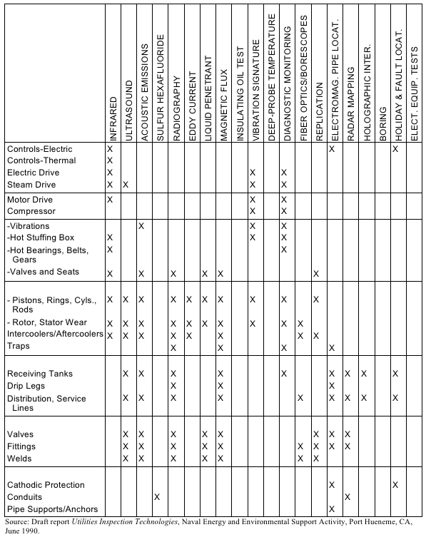
F.4.1 Utility Systems: Compressed Air
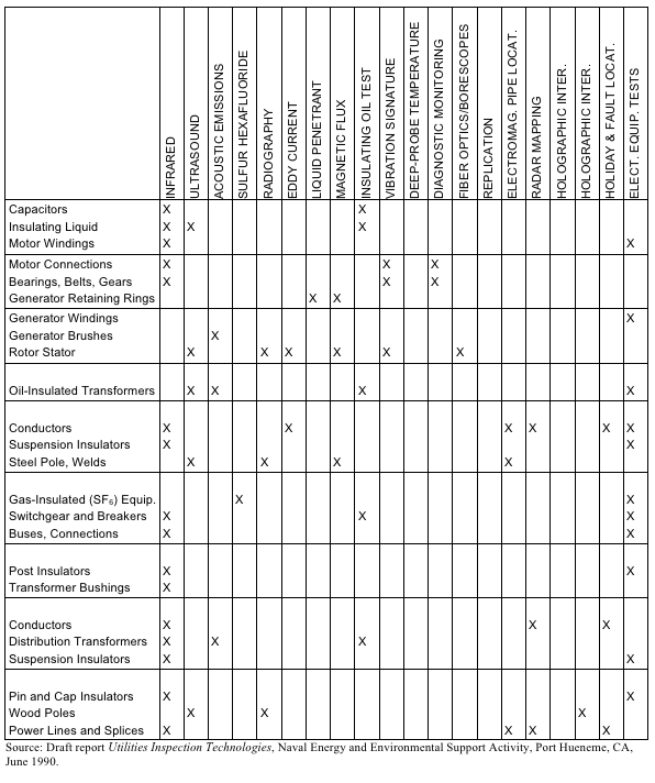
F.4.2 Utility Systems: Electrical
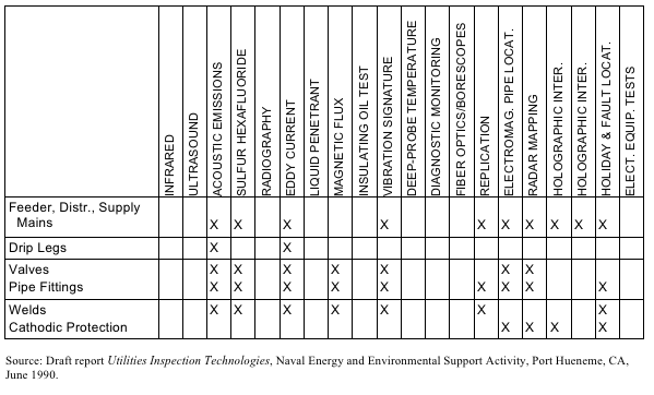
F.4.3 Utility Systems: Natural Gas
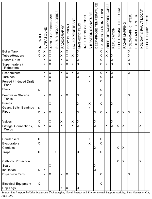
F.4.4 Utility Systems: Steam
F.4.5 Utility Systems: Hot Water
| TOC | Change History | Preface | Chapter1 | Chapter2 | Chapter3 | Chapter4 | Chapter5 | Chapter6 | Chapter7 | Chapter8 | Chapter9 | Chapter10 | Chapter11 | Chapter12 | AppendixA | AppendixB | AppendixC | AppendixD | AppendixE | AppendixF | AppendixG | AppendixH | AppendixI | ALL | |
| | NODIS Library | Program Management(8000s) | Search | |
This document does not bind the public, except as authorized by law or as incorporated into a contract. This document is uncontrolled when printed. Check the NASA Online Directives Information System (NODIS) Library to verify that this is the correct version before use: https://nodis3.gsfc.nasa.gov.